Proceedings of the 2005 IEEE International Conference on Robotics and Automation Barcelona, Spain, April 2005
Dimensioning a Constrained Parallel Robot to Reach a Set of Task Positions∗ Hai-Jun Su
J. Michael McCarthy
Virtual Reality Application Center Iowa State University Ames, IA 50011, USA
[email protected]
Department of Mechanical and Aerospace Engineering University of California Irvine, CA 92697, USA
[email protected]
Abstract— The paper considers the problem of setting the dimensions of a system of constrained parallel robots to ensure that together they can position an end-effector in a specified set of positions. The focus is on five degree-offreedom serial chains that provide point contact, modelled as a spherical joint, with the end-effector. We identify seven such chains which can be used to form 756 parallel robots ranging from one to three degrees of freedom. The algebraic equations of the surfaces that contain the center of the spherical joint of these seven chains can be used to form the design equations for the parallel system. These equations are solved to determine some or all of the structural parameters depending upon the required number of task positions. We demonstrate this by computing the dimensions of a symmetric 3CS parallel robot such that it guides the end-effector through three arbitrarily defined task positions.
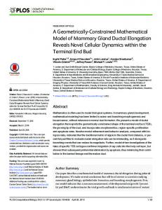
M1
Mn M
P1
p3
p1
P3
p2 P2
Revolute Prismatic
Fig. 1. A parallel constrained robot assembled from an RRS, RPS and PRS serial chain.
Index Terms— Parallel robots, robot design, path planning,
I. I NTRODUCTION This paper examines the geometric design of parallel manipulators constructed from five degree-of-freedom serial chains that provide a point contact with the end-effector. This point contact is modelled as a spherical joint with three degrees of freedom. The two remaining joints in the chain position the center of the spherical joint on a surface in space. This surface characterizes the chain, and is termed its reachable surface. The algebraic equation of the reachable surface is used to formulate equations that dimension the chain such that it can position its end-effector at a given set of task positions. Chen and Roth [1] introduced this problem in their application of kinematic synthesis principles to the design of robot manipulators. The extension of this idea to parallel manipulators constructed from constrained serial chains was studied by Kim and Tsai [2]. Also see, Fang and Tsai [3] and Huang and Li [4]. Recently, we obtained solutions for the general cases of dimensional synthesis of the seven serial chains with reachable surfaces, Su et al. [5], which range in complexity from degree 32 for the PPS chain to over 4 106 for the RRS chain. A primitive result on the synthesis of 3RRS parallel robot is provided in [6]. ∗ This work is partially supported by NSF Grant DMII 0218285 to J. Michael McCarthy
0-7803-8914-X/05/$20.00 ©2005 IEEE.
In this paper, we assemble combinations of these surface equations into polynomial systems that we solve to dimension a parallel robot system so it can reach a set of task positions. This provides the ability to adapt a reconfigurable or modular system of robots to a change in task (Moon and Kota [7], Yang and Chen [8]). In what follows, we present the design equations for each of the serial chains, and show how they are assembled to define a constrained parallel robot (Figure 1). Two examples of the synthesis of a 3CS platform are used to illustrate the procedure. The system is configured so that the axes of the C-joints are parallel and we consider the cases: (i) identification of base locations so a given symmetric triangular platform can reach three arbitrary positions, and (ii) identification of symmetric base and symmetric platform for three arbitrary task positions. In the first case, the design equations are linear and there is a unique solution. The second case requires the solution of a polynomial system of degree 512, and we use our polynomial homotopy solver to obtain 10 real roots. II. S ERIAL C HAIN P RIMITIVES The serial chains used in our parallel robots are five degrees-of-freedom and which connect to the end-effector with a three degree-of-freedom spherical joint. Thus, the remaining two degrees-of-freedom are provided by one of the four combinations of revolute and prismatic joints: PP, RP, PR, and RR. We also consider three additional 4037
Case 1 2 3 4 5 6 7
Chain PPS (R⊥PS,P⊥RS,RkRS) PRS RPS RRS CS R⊥RS TS
n 6 10 10 12 8 10 7
Surface plane elliptic cylinder hyperboloid general torus circular cylinder circular torus sphere
TABLE I T HE BASIC SERIAL CHAINS AND THEIR ASSOCIATED REACHABLE SURFACES .
special cases, i) the cylindric joint, denoted by “C”, which is a RP or PR chain with parallel axes, ii) the universal joint, denoted by “T”, which is a RR chain with two axes intersecting at a right angle, and iii) the perpendicular RR chain, denoted by “R⊥R” when the two axes are perpendicular but not intersecting. As a result we have seven serial chains PPS, RPS, PRS, RRS, CS, TS, R⊥RS. Su et. al. [5] showed that the trajectory of the spherical wrist of these seven chains form seven surfaces—plane, circular hyperboloid, elliptic cylinder, general torus, circular cylinder, sphere and right torus. Note the S-joint of a perpendicular RPS or PRS denoted by R⊥PS and P⊥RS forms a plan, thus we classify this case as PPS. Similarly the “parallel” RRS case denoted by RkRS can be also classified as PPS. The result is a set of seven algebraic surfaces that are reachable by the wrist centers of a set of articulated chains. See Table I and Figure 2. III. S ERIAL C HAIN S YNTHESIS Because the spherical wrist allows all orientation of the end-effector, the synthesis problems we consider are equivalent to seeking points on the end-effector that lie on their associated reachable surfaces. We let P be the spherical wrist center. Essentially we require P satisfy the following seven surface equations (Su et al. [5]). A. Seven Surface Equations a) Plane Equation: The PPS serial chain has the feature that the wrist center P is constrained to lie on a plane. That is, P must satisfy the plane equation G · P − d = 0,
Fig. 2.
c) Circular Hyperboloid Equation: The S-joint of a RPS chain forms a circular hyperboloid. Thus P must satisfy (P − B)2 − ((P − B) · G)2 (1 + tan2 α) − R2 = 0, (3) where G is the direction of the R joint axis, α is the angle of the R and P joint axes and R is the common distance of the two axes. d) General Torus Equation: The S-joint P of a RRS chain lies on a general torus
2
where S1 and S2 are the axes of the P and R joint respectively, B is a point on the R joint axis and R is the shortest distance from the S-joint center to the R-joint axis.
((P − B)2 − ρ2 − d2 − R2 )2 +
4ρ ((P sin2 α
(1)
where G is the directional vector normal the plane and d is the product of the magnitude |G| and the signed normal distance to the plane. b) Elliptic Cylinder Equation: The wrist center P of a PRS chain lie on an elliptic cylinder, that is ¡ ¢¢2 ¡ − R2 (S1 · S2 )2 = 0, (2) S2 × (P − B) × S1
Seven serial chain primitives
− B) · G − d cos α)2 − 4ρ2 R2 = 0,
(4)
where G and B are the direction of and a point on the first R joint axis respectively, α and ρ are the twist angle and normal distance of the two R joints, R is the normal distance from the S-joint to the second joint axis, and d is the offset of the second R joint. e) Sphere Equation: The trajectory of the wrist center P of a TS chain is constrained to lie on a sphere, that is, (P − B)2 − R2 = 0,
(5)
where B is the center of the T-joint and R is the distance from B to the S-joint center. 4038
m 3 4 5
DOF 3 2 1
Toplogies 84 210 462
G3
TABLE II
B3
N UMBER OF PLATFORM TOPOLOGIES FORMED BY THE SEVEN SERIAL CHAINS .
P3 G1
[M]
G2
p3 C-joint P2
p1 p2
R1
f) Circular Cylinder Equation: When the P and R joint axes in a PRS chain are parallel, the elliptic cylinder degenerates to a circular cylinder, ((P − B) × G)2 − R2 = 0,
(7)
B. Design Equations In what follows, we let matrices [M i ] = [Ai , di ], i = 1, . . . , n denote the given task positions, where [Ai ] is a 3×3 rotation matrix and di is a 3×1 translation vector. Our goal is to seek for the dimensions of a serial chain such that its end-effector passes through these task positions [M i ]. Let p = (p1 , p2 , p3 )T be the position vector of the spherical wrist with respect to the moving frame. The position of the spherical wrist in the base frame for each of the task positions can be computed as Pi = [M i ]p = [Ai ]p + di . The design equations are obtained by substituting Pi to the associated surface equation. For example, the n position CS design equations are obtained by substituting Pi into the circular cylinder equation (6), that is CS: ((Pi − B) × G)2 − R2 = 0, i = 1, . . . , n
Platform
S-joint
B2
Cylinder surfaces
(6)
where we have used S1 = S2 = G in equation (2). g) Circular Torus Equation: If the two R joint axes are perpendicular, the general torus becomes a circular torus given by ((P − B)2 − ρ2 − R2 )2 + 4ρ2 ((P − B) · G)2 − 4ρ2 R2 = 0.
P1
B1
(8)
where eight parameters have to be determined: scalar R, two for G, three for p two for B. Therefore we can design a CS chain to reach up to n = 8 task positions. IV. PARALLEL ROBOTS A parallel robot is formed by assembling a number of serial chains so they have a common base and a common end-effector. We can determine the parallel topologies that can be assembled from our seven serial chain primitives in Table I. We require 3 ≤ m ≤ 5 supporting chains. Therefore the number of combinations of m chains taken from the list of seven available, allowing repetition, yields µ ¶ 7+m−1 . (9) m Applying this formula for values m = 3, 4, 5, we can count the constrained parallel robots, Table II. Note the second column is the degree-of-freedom of the corresponding
Fig. 3.
A symmetric 3CS platform
parallel chain, given by 6 − m. We can see that there are total of 756 parallel linkages that can be assembled from the seven serial chain primitives. Among them, 84 parallel robots have three limbs or three degree-of-freedom, 210 and 462 have four and five limbs respectively. V. K INEMATIC S YNTHESIS OF PARALLEL ROBOTS The design equations for the parallel chains are obtained from the design equations for each of its supporting serial chains. As before, we let matrices [M i ] = [Ai , di ], i = 1, . . . , n denote the n given task positions. And let pj , j = 1, . . . , m be the position vectors of the spherical joints in the moving frame, where m is the number of sub chains (limbs) or S joints. The position of the spherical wrist in the base frame for each of the task positions can be computed as (10) Pij = [M i ]pj = [Ai ]pj + di Substituting Pij to the associated surface equation of each chain yields the mn algebraic design equations. For example, the parallel manipulator in Figure 1 has three sub chains, R⊥RS, PRS, and RPS. We assemble the design equations for each of three sub chains to obtain RRS : ((Pi1 − B1 )2 − ρ2 − R21 )2 + i 4ρ2 ((P1 − B1 ) · G1 )2 − 4ρ2 R21 = 0 i 2 RPS : (P2 − B2 ) − , i 2 2 2 ((P − B ) · G ) (1 + tan α) − R = 0 2 2 2 2 ¡ ¡ ¢¢2 − R32 (S1 · S2 )2 = 0 PRS : S2 × (Pi3 − B3 ) × S1 (11) where i = 1, . . . , n. From Table I, we know the maximum number of task position for R⊥RS, PRS, and RPS are all 10. Therefore we can specify up to n = 10 task positions, in which case we have to solve 30 polynomial equations in 30 unknowns. In many practical applications, designers often tend to use the same topology for all sub chains. An example is 3CS parallel robot (Figure 3). Let Gi , Bi = (Bix , Biy , Biz )T , (i = 1, 2, 3) be the direction of and a point on the three C-joint axes. And let Ri be the normal distance from the spherical center Pi to the axis Gi . 4039
Chain 1 2 3
[T1] [T3]
Bix 1.5015 -1.2860 -0.7408
Biy 0.8689 0.8823 1.6771
Ri 0.8689 0.8823 2.9761
TABLE III T HE UNIQUE SOLUTION TO THE 3CS THREE POSITION SYNTHESIS (E XAMPLE 1)
[T2]
Fig. 4.
[T1]
A 3CS platform reaching the three task positions (Example 1)
[T3]
The design equations for 3CS parallel robot can be obtained by writing the CS chain design equation (16) three times, that is, i CS1 : ((P1 − B1 ) × G1 )2 − R12 = 0, (12) CS2 : ((Pi2 − B2 ) × G2 )2 − R22 = 0, , CS3 : ((Pi3 − B3 ) × G3 )2 − R32 = 0,
where i = 1, . . . , n. Since each CS serial chain has eight parameters (Table I), a 3CS parallel chain has 3 × 8 = 24 parameters to be determined. The design equations can be further simplified by constraining the dimensions of the parallel robot. These free choices can be any combination of the shape of the base and platform, the link length and angle of the limbs. As a result, the designers gain a better control to the design process. VI. E XAMPLE 1: 3CS WITH A S YMMETRIC P LATFORM
As an example, we consider a three position synthesis of 3CS parallel robots. Let the task positions of the endeffector are given by the following three 4 × 4 matrices: 1 0 0 0 0 1 0 0 (13) M1 = 0 0 1 1 0 0 0 1
0.7660 −0.6428 0.0 −0.5 0.6040 0.7198 0.3420 0.2 M2 = −0.2198 −0.2620 0.9397 1.4 0.0 0.0 0.0 1.0
0.5063 −0.8140 0.2845 0.6 0.8139 0.3421 −0.4695 0.4 M3 = 0.2848 0.4693 0.8358 1.2 0.0 0.0 0.0 1.0
(14)
[T2]
Fig. 5.
to eliminate Ri . Thus, we obtain k 1 CS1 : ((P1 − B1 ) × G1 )2 − ((P1 − B1 ) × G1 )2 = 0, CS2 : ((Pk2 − B2 ) × G2 )2 − ((P12 − B2 ) × G2 )2 = 0, , CS3 : ((Pk3 − B3 ) × G3 )2 − ((P13 − B3 ) × G3 )2 = 0 (16) where k = 2, 3. Now we choose G1 = G2 = G3 = (0, 0, 1)T , and p1 = (1.5, 0, −0.2)T , p2 = (−0.75, 1.2990, −0.2)T , p3 = (−0.75, −1.2990, −0.2)T . Note the three spherical joints form a right triangle in the platform. The position vector Pi1 , Pi2 , Pi3 of the three S-joint in the platform [M i ] can be computed by equation (10). Furthermore we set B1z = B2z = B3z = 0. Since the square terms are simply cancelled, system (12) consists of six linear equations in six unknowns (B1x , B1y , B2x , B2y , B2x , B2y ). Solving this linear system yields the unique solution, shown in Table III. Figure 4 illustrates the chain reach the three task positions. This display uses our S YNTHETICA software, which is a general purpose mechanism synthesis and simulation software (Collins et al. [9], and Su et al. [10]). VII. E XAMPLE 2: T HE S YMMETRIC 3CS
(15)
The design equation (12) contains nine polynomials with 24 unknowns. Clearly, we have freedom to control the geometric parameters of the 3CS platform. Before that, we first reduce the problem complexity by subtracting the first equation from the other two equations
Solution no.5 reaching the task positions (Example 2)
In this example, we still design 3CS reaching the three task positions provided in the previous example. As before, we choose the direction of the three cylindric joint G1 = G2 = G3 = (0, 0, 1)T . However this time we require that each three CS chain has the same radius R, that is R1 = R2 = R3 = R. 4040
(17)
Sol. 1 2 3 4 5 6 7 8 9 10
R 0.658 0.721 0.721 0.721 0.778 0.778 0.778 27.496 27.496 27.496
p1x 0.000 0.776 -0.702 -0.074 0.581 0.201 -0.782 -2.560 29.428 -26.869
p1y 0.000 -0.363 -0.491 0.854 -0.567 0.787 -0.219 -32.503 14.035 18.468
B1x -0.096 1.048 -0.002 -0.662 1.086 -0.343 -0.227 -0.707 4.822 -5.710
B1y 0.651 0.304 -0.661 1.270 0.025 0.231 -0.765 -5.070 1.765 0.909
B2x -0.096 -0.662 1.048 -0.002 -0.343 -0.227 1.086 4.822 -5.710 -0.707
B2y 0.651 1.270 0.304 -0.661 0.231 -0.765 0.025 1.765 0.909 -5.070
TABLE IV T EN REAL SOLUTIONS FOR THE SYMMETRIC 3CS PLATFORM (E XAMPLE 2)
The 3CS design equation (12) becomes i CS1 : ((P1 − B1 ) × G1 )2 − R2 = 0, CS2 : ((Pi2 − B2 ) × G2 )2 − R2 = 0, , CS3 : ((Pi3 − B3 ) × G3 )2 − R2 = 0,
(18)
p3 = [Z(4π/3)]p1 .
B3y 0.651 -0.661 1.270 0.304 -0.765 0.025 0.231 0.909 -5.070 1.765
with parallel joint axes. In order to obtain a symmetric the base and platform for this chain, we solve a system of nine quadratic equations, using our polynomial homotopy solver POLSYS GLP. The result is 10 real roots that define three different platforms that reach three arbitrarily specified endeffector positions. R EFERENCES
where i = 1, 2, 3. Design equation (18) is a system of nine quadratic polynomials with total degree of 29 = 512. Since we are interested in symmetric platforms, we require that the three S-joints p1 , p2 , p3 lie on a right triangle in the platform. Thus given the coordinates of p1 = (p1x , p1y , p1z )T , we compute p2 , p3 by p2 = [Z(2π/3)]p1 ,
B3x -0.096 -0.002 -0.662 1.048 -0.227 1.086 -0.343 -5.710 -0.707 4.822
(19)
Furthermore, we choose B1z = B2z = B3z = 0 and p1z = −0.2. Therefore, the design equation (18) contains 9 unknowns (R, p1x , p1y , B1x , B1y , B2x , B2y , B3x , B3y ). We used our polynomial homotopy solver POLSYS GLP to solve equations (18). Polynomial homotopy, also known as polynomial continuation, is a method to find all of the isolated solutions to systems of polynomial equations. The method is based on the fact that small changes in the coefficients of a polynomial system result in small changes to the system of roots. Our POLSYS GLP (Su et. al. [11]) homotopy solver is a generalized version of the POLSYS PLP developed by Wise et al. [12]. It is a Fortran routine that runs in a parallel computing environment. For this example we obtained 76 solutions, 10 of them are real and listed in Table IV. Notice that solution 1 is a degenerate case. The other nine solutions separate into three groups, each of which corresponds to one platform design. Figure 5 illustrates the chain reach the three task positions. VIII. C ONCLUSION This paper present a design methodology for constrained parallel robots. We identify seven five degree-of-freedom serial chains that end in spherical joints, each of which is characterized by a reachable surface. The algebraic equations of these surfaces, for each of the supporting legs of a parallel robot, are assembled together to form a polynomial system that is solved to set the dimensions of the robot. We demonstrate the formulation and the solution of these design equations for two versions of a 3CS parallel robot
[1] Chen, P. and Roth, B., 1967, “Design Equations for Finitely and Infinitesimally Separated Position Synthesis of Binary Link and Combined Link Chains,” ASME J. Engineering for Industry 91:209219. [2] H.S. Kim and L.-W. Tsai, “Kinematic Synthesis of a Spatial 3-RPS Parallel Manipulator”, ASME Journal of Mechanical Design, Vol.124, no. 1, pp. 92-97, 2003. [3] Fang, Y., and Tsai, L-W, 2002, “Structure Synthesis of a Class of 4-DoF and 5-DoF Parallel Manipulators with Identical Limb Structures,” The International Journal of Robotics Research, 21(9):799810. [4] Huang, Z. and Li, Q. C., 2003, “Type Synthesis of Symmetrical Lower-mobility Parallel Mechanisms Using the Constraint-synthesis Method, The International Journal of Robotics Research, 22(1):5979. [5] Su, H.-J., McCarthy, J. M. , and Watson, L. , 2004, “Generalized Linear Product Homotopy Algorithms and the Computation of Reachable Surfaces,” ASME Journal of Computers and Information Science and Engineering, vol.4, no. 3, pp. 226-234, 2004. [6] Wolbrecht, E., Su, H.-J., Perez, A. and McCarthy, J.M., 2004, “ Geometric Design of Symmetric 3-RRS Constrained Parallel Platforms,”, ASME International Mechanical Engineering Congress and Exposition, Nov. 13-19, Ahnaheim, CA. [7] Moon, Y.-M., and Kota, S, 2002, “Generalized Kinematic Modeling of Reconfigurable Machine Tools,” ASME Journal of Mechanical Design, 124(1):47-51. [8] Yang. G, and Chen, I-M, 2000, “Task-based optimization of modular robot configurations: minimized degree-of-freedom approach,” Mechanism and Machine Theory 35:517-540. [9] C. L. Collins, J. M. McCarthy, A. Perez, and H. Su, “The Structure of an Extensible Java Applet for Spatial Linkage Synthesis,” ASME Journal of Computing and Information Science and Engineering, 2(1):45-49, March 2002. [10] Su, H.-J., Collins, C., McCarthy, J. M., 2002, “An Extensible Java Applet for Spatial Linkage Synthesis,” DETC2002/MECH-34371, ASME Design Engineering Technical Conference, Montreal, Canada, Sept.29-Oct.02, 2002. [11] Su, H.-J., McCarthy,J.M, Sosonkina, M. and Watson, L.T., “POLSYS GLP: A Parallel General Linear Product Homotopy Code,” submitted July 2004 to ACM Trans. on Mathematical Software. [12] Wise, S. M., Sommese, A. J., and Watson, L. T., 2000, “Algorithm 801: POLSYS PLP: A partitioned linear product homotopy code for solving polynomial systems of equations,” ACM Trans. Math. Software, 26:176–200.
4041