DIRECT PWOER CONTROL BASED ARTIFICIAL NEURAL NETWORK OF DOUBLY FED INDUCTION GENERATOR FOR WIND ENERGY CONVERSION SYSTEMS YOUCEF DJERIRI 1 , ABDELKADER MEROUFEL, AHMED MASSOUM
Keywords: Wind energy, Doubly fed induction generator, Direct power control, Artificial neural networks, Multilayer perceptron. This paper proposes a Direct Power Control (DPC) strategy for a Doubly Fed Induction Generator (DFIG) based wind power generation system, using a Multilayer Perceptron (MLP) controller. This controller replaces the conventional DPC lookup table and allows the converter that is connected to the rotor terminals to operate with constant switching frequency. The digital simulation results of 1.5MW DFIG are presented to show the validity and efficiency of the proposed control strategy to decouple and control the active and reactive power in different conditions of wind speed.
1.
INTRODUCTION
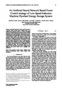
With ever increasing concerns about the world’s fossil fuel reserves as well as CO2 emissions, renewable energy sources, especially wind power, have found more attentions. Indeed, wind energy has become an important source for electricity generation in many countries [1]. It is expected that wind energy will provide about 10% of the world’s electrical energy in 2020 [2–3]. Nowadays, the concept of the variable speed wind turbine (VSWT) equipped with a Doubly Fed Induction Generator (DFIG) has received increasing attention due to its noticeable advantages compared to the fixed speed induction generators [4–5], such as increased power capture, four-quadrant converter topology which lets the decoupled and fast active and reactive power control and reduced mechanical stresses [6]. In the DFIG concept, the stator is usually connected directly to the threephase grid; the rotor is also connected to the grid but through a transformer and a variable frequency converter as shown in the Fig. 1. Usually, the rotor-side converter controls the active and reactive power and the grid side converter controls the DC-link voltage and ensures operation of the converter at a unity power factor [7]. 1
University of Sidi Bel-Abbes, 22000, Algeria, E-mail :
[email protected]
Rev. Roum. Sci. Techn.– Électrotechn. et Énerg., 54, 1, p.
, Bucarest, 2009
2
Youcef Djeriri, Abdelkader Meroufel, Ahmed Massoum
DFIG-Side Control
2
Grid-Side Control
Fig. 1 – Wind turbine conversion system based DFIG.
This arrangement (Fig. 1) provides flexibility of operation in subsynchronous and supersynchronous speeds in both generating and motoring modes (±30% around the synchronous speed). By consequence, the power converter needs to handle a fraction (20–30%) of the total power to achieve full control of the generator. Such the system also results in lower converter costs and lower power losses compared to fully variable speed wind generation systems with a full-rated converter. Control of DFIG wind turbine systems is traditionally based on rotor current vector control with d–q decoupling [8–9]. The control system is usually defined in the synchronous d–q frame fixed to either the stator voltage [10–11] or the stator flux [12–13] and it involves relatively complex transformation of voltages, currents and control outputs among the stationary, the rotor and the synchronous reference frames; control of the active and reactive power is achieved indirectly by controlling the input currents. Traditionally, the Proportional-Integral (PI) controllers, because of their simple structures, are still the most commonly used controllers in power systems, as can be seen in the control of the wind turbines equipped with DFIGs [10–14–15–16–17]. Unfortunately, tuning the PI controllers is tedious and it might be difficult to tune the PI gains properly due to the nonlinearity and the high complexity of the system. Another main drawback of this regulator is that its performance depends greatly on accurate machine parameters such as rotor resistance and inductance, and mutual inductance [17]. Nowadays, direct control techniques for AC machines have found a lot of interests due to their simplicity and high dynamic performances. Direct torque control (DTC) was first introduced by I. Takahashi in 1986 [18], the DTC directly
3
DPC control based artificial neural networks of DFIG
3
controls the developed torque by the machine with the use of torque and flux information and selects the best voltage vector using a switching table. Then, the direct self control (DSC) was developed in Germany by M. Depenprock in 1988 [19]; it’s just a simplified version of DTC technique, because although the torque is also controlled by a simple hysteresis controller bandwidths, flux is not it. After that, direct power control (DPC) was developed and presented in 1998 by T. Noguchi [20]; it’s based on the same control principles as the DTC technique, the unique difference is the directly controlled variables. In the case of the DTC, the electromagnetic torque and the rotor flux are directly controlled while in the DPC, the stator active and reactive powers are controlled. Recently, DPC control of DFIG based wind energy generation systems has been proposed [21–22], and it’s proven to have many advantages compared to the vector control technique, such as simplicity, fast dynamics and robustness against parameters variations and grid disturbances [17]. However, when DPC operate at a variable switching frequency [17–23], its makes the power converter and the AC harmonic filter complicated and expensive. More recently, several papers have been published on DPC at constant switching frequency for DFIG, proposing new modified DPC strategies and improvements of the system. In [24] DPC at constant switching frequency is developed for DFIG, using a Space Vector Modulation (SVM) algorithm. In [25] the Discrete Space Vector Modulation (DSVM) is applied to fit a better switching table, used in the control. A predictive direct power control strategy is proposed in [26–27], aiming to reduce the power errors and improve the performance of the control. However these methods have complex algorithms which make them inefficient for practical implementations. In [28], fuzzy and DSVM are combined to minimize the power ripples, however this is also uses a switching table. Furthermore it has so much rules and a high switching frequency is needed to effectively reduce the power ripples. In [29] the fuzzy logic control (FLC) and SVM technique are combined and gained a good performance for DPC of DFIG based wind energy conversion system. In this paper a DPC with constant switching frequency was proposed, which allows the performance of DPC scheme in terms of active and reactive power ripples and current distortion to be improved. These improvements could be achieved with simple control circuit without increasing the inverter switching frequency. This control algorithm is based on an Artificial Neural Network (ANN) with the multilayer perceptron (MLP) structure. By suitable selection of the best structure of MLP, the complexity of the proposed method is less than the method presented by [30]. The controller generates the gate pulses for the rotor side converter from inputs values: active and reactive power errors and rotor flux position. Simulation results on a 1.5MW DFIG generation system are presented to demonstrate the performance of the proposed control strategy.
4
Youcef Djeriri, Abdelkader Meroufel, Ahmed Massoum
2.
4
WIND TURBINE MODEL
The relation between the wind speed and mechanic power, delivered by the wind turbine, can be described by the following equation: Pt
1 R 2 v 3C p , 2
(1)
With:
r R v
(2)
Where: Cp: power coefficient; λ: relative speed; β: pitch angle (deg); R: radius of turbine (35.25m); Ωr: turbine speed (rd/s); v: wind speed (m/s); ρ: air density (1.225kg.m-3). For the variables speed wind turbines, the approximate expression of the power coefficient can be described by the following expression [31]: 151 18.4 C p f ( , ) 0.73 0.58 0.002 2.14 exp i i
(3)
Where: 1
i
1 0.003 3 0.02 1
(4)
The electromagnetic torque produced by the turbine is expressed in the following way: P 1 2 (5) Tt t R 3v Ct , r 2 Where Ct is the torque coefficient expressed by: Ct
Cp
(6)
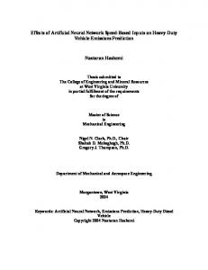
Fig. 2 shows the characteristic of the power coefficient, with a fixed pitch angle β, for the 1.5MW turbine used in this work.
5
DPC control based artificial neural networks of DFIG
5
Fig. 2 – Pitch angle effect on the torque coefficient.
3.
DYNAMIC MODEL OF DFIG
For decoupled control of active and reactive power, dynamic model of DFIG is required. The equivalent circuit of DFIG in synchronously rotating reference frame is shown in Fig. 3.
s
s
s
r
r
Fig. 3 – Equivalent circuit of DFIG.
The voltage equations of the DFIG in the synchronous d-q reference frame rotating at ωs are as follows:
d ds s qs dt d Vqs Rs I qs qs s ds dt Vds Rs I ds
(7) (8)
6
Youcef Djeriri, Abdelkader Meroufel, Ahmed Massoum
d dr (s r ) qr dt d Vqr Rr I qr qr ( s r ) dr dt
Vdr Rr I dr
6
(9) (10)
Where: 𝜔s: stator angular frequency in rad/s 𝜔𝑟: rotor angular speed in rad/s (𝜔s − 𝜔𝑟): slip angular frequency in rad/s The flux linkages are :
ds Ls I ds Lm I dr qs Ls I qs Lm I qr
dr Lr I dr Lm I ds qr Lr I qr Lm I qs
(11) (12) (13) (14)
DFIG electromagnetic torque is: 3 Lm (15) ds I qr qs I dr p 2 Lr Generator active and reactive powers at the stator side are given by the following expressions: Tem
Ps
3 VdsI ds VqsI qs 2
(16)
Qs
3 Vqs I ds Vds I qs 2
(17)
The rotor-side converter is controlled in a synchronously rotating d-q axis frame, with the d-axis oriented along the stator flux vector position (Fig. 4). In this approach, decoupled control between the stator active and reactive powers is obtained. The influence of the stator resistance can be neglected and the stator flux can be held constant as the stator is connected to the grid. Consequently [12]:
7
DPC control based artificial neural networks of DFIG
7
ds s and qs 0 Stator axis Rotor axis d-q reference frame α-β reference frame
β B q b
(18)
Ψr
ωs
Vs
Iqs
Ψs
δ
Is
θsl
d ωr
a
θs
Ids θr α
A
Fig. 4 – Stator field oriented control technique.
In this case : Vds 0 Vqs Vs s . s
(19)
s Ls I ds Lm I dr 0 Ls I qs Lm I qr
(20)
s Lm I ds L L I dr s r L I m I qs qr Ls
(21)
3 Ps 2 Vs I qs Q 3 V I s 2 s ds
(22)
Replacing the stator currents by their expressions given in (11), the equations below are expressed:
8
Youcef Djeriri, Abdelkader Meroufel, Ahmed Massoum
8
3 Lm Ps 2 L V s I qr s Q 3 V V s Lm I s 2 s L s . s L s dr
(23)
The electromagnetic torque is as follows: 3 L Tem p m s I qr 2 Ls
(24)
Rotor voltages can be expressed by: 2 L Vdr Rr I dr g s Lr m I qr Ls 2 Lm LV I dr g m s V R I g L r qr s r qr Ls Ls
(25)
The resulting bloc diagram of the DFIG is presented in Fig. 5. g Lm Vs / Ls Vqr
1
_ +_
L2 Rr p Lr m Ls
Iqr
- Lm Vs / Ls
3/2
Ps
3/2
Qs
g 𝜔𝑠 (𝐿𝑟−(Lm2∕𝐿𝑠)) g 𝜔𝑠 (𝐿𝑟−(Lm2∕𝐿𝑠))
Vs2/ Ls 𝜔𝑠
1 Vdr
+ +
L2 Rr p Lr m Ls
-Lm Vs / Ls
++
Idr
Fig. 5 – The bloc digram of the simplified DFIG.
4.
CONVENTIONAL DPC STRATEGY PRINCIPLE
(
9
DPC control based artificial neural networks of DFIG
9
By using pervious equations and neglecting the stator resistance; we can find the relations of Ps and Qs according to both components of the rotor flux in the stationary αr-βr reference frame, and we can get: 3 Lm Ps 2 L L Vs r s r Q 3 V 1 Lm s 2 s Ls s Ls Lr r
(26)
Where: 2 L L r Lr m Ir m s Ls Ls 2 Lm I r L r r Ls L L L2 / L L s r m s r
(27)
The fact that the stator is directly connected to the grid provides a stator flux vector with a constant amplitude:
s
Vs
s
(28)
If we introducing the angle δ between the rotor and stator flux linkage, Ps and Qs become: 3 Lm Ps 2 L L s s r sin s r (29) L 3 s Q m cos s s 2 Ls s Lr r Differentiating (24) results in the following equations:
dPs d r sin 3 Lm s s 2 Ls Lr dt dt dQs 3 Lm s d r cos s dt 2 Ls Lr dt
(30)
10
Youcef Djeriri, Abdelkader Meroufel, Ahmed Massoum
10
Hence, the last two expressions show that the stator active and reactive powers can be controlled by modifying the relative angle between the rotor and stator flux space vectors and their amplitudes as shown in Fig. 6. βs
βr
α-β stator reference frame α-β rotor reference frame
Ψr
Ψs
ωr
δ Ψr cos δ
θsl Ψr sin δ
αr θs
θr
αs Fig. 6 – Relation of stator and rotor flux linkage vectors in stationary and rotor reference frames.
As shown in Fig. 3, similar to the stator flux, the rotor flux of a DFIG in the rotor (αr–βr) frame can be expressed as: dr (31) Vr Rr I r dt Neglecting the effect of rotor resistance Rr, (31) indicates that the variation of rotor flux is determined by the applied rotor voltage. The rotor flux moves at the direction of applied rotor voltage vector and its speed is proportional to the amplitude of the voltage vector applied. Therefore, by selecting appropriate voltage vectors, themovement of the rotor flux can be controlled. The selection of the voltage vector also depends on the location of the flux linkage and the (αr–βr) plane is divided into six regions as shown in Fig. 7.
11
DPC control based artificial neural networks of DFIG
11
Fig. 7 – Flux vectors in rotor coordinates for generating mode.
Based on the effects of the voltage vector on the variations of the powers, the conventional DPC strategy based a three-phase two level converter was presented in [17–23], eight switching combinations can be selected; two of them determine zero voltage vectors and the remains generate six space voltage vectors that have the same magnitude. Firstly In this method, stator active and reactive powers are estimated, then sector position of the rotor flux (k) is calculated. Hysteresis block is applied to compare the active and reactive powers with their reference values. Finally, the hysteresis outputs (Hp and Hq) and sector of rotor flux are used to choose the appropriate voltage vector from a switching table [22–23]. The selected voltage vector is applied to the rotor (Fig. 8).
12
Youcef Djeriri, Abdelkader Meroufel, Ahmed Massoum
12
Transformer $ $
Rectifier Hysteresis controllers Switching HP table
Ps*
DC bus
Si
+ + -
Qs*
Filter
HQ
Qs Ps
DFIG Inverter
k
Ps, Qs
Grid
Ir αβ
α,β
Ir
and sector estimation
Vs αβ
a,b,c
Vs
Fig. 8 – Schematic diagram of DPC strategy for DFIG.
5.
DPC BASED ARTIFICIAL NEURAL NETWORKS
ANN has a very significant role in the field of artificial intelligence. The artificial neurons learn from the data fed to them and keep on decreasing the error during training time and once trained properly, their results are very much same to the results required from them, thus referred to as universal approximators [32]. The most popular neural network used by researchers are the multilayer feed forward neural network trained by the back propagation algorithm [33] .There are different kinds of neural networks classified according to operations they perform or the way of interconnection of neurons. Some approaches use neural networks for parameters estimation of electrical machines in feedback control of their speeds [34]. Here we have used a feed forward neural network to select the voltage vector which replaces the lookup table in the case of C-DPC strategy. In the case presented in this paper the DPC control strategy shown in the section 3 has been implemented. Neural network has been devised having as inputs the active power error, the reactive power error and the position of the flux sector and as output the gate pulses for the tow levels voltage source inverter (2L-VSI) which supplies the rotor windings as we shown in Fig. 9. The MLP controller then replaces the switching table selector block of the Fig. 8.
13
DPC control based artificial neural networks of DFIG
13
Transformer $ $
Hysteresis controllers
HP
Ps*
Rectifier DC bus
Si
+ Qs*
Filter
MLP controller
+ -
Qs Ps
HQ
DFIG Inverter
k
Ps, Qs
Grid
Ir αβ
α,β
Ir
and sector estimation
Vs αβ
a,b,c
Vs
Fig. 9 – DPC neural networks controller scheme.
The network taken in this study is a 3–35–3 feed-forward network with first layer of log sigmoid transfer function, second layer of hyperbolic tangent sigmoid transfer function and third layer of linear transfer function. Training method used was again back-propagation. All the three neural networks were trained to performance 0.01 msec. The back-propagation algorithm is used to train the neural networks. The training function used is Levenberg-Marquardt (LVM) back propagation [35–36], it updates weights and bias values according to Levenberg-Marquardt optimization algorithm. As soon as the training procedure is over, the neural network gives almost the same output pattern for the same or nearby values of input. This tendency of the neural networks which approximates the output for new input data is the reason for which they are used as intelligent systems.
14
Youcef Djeriri, Abdelkader Meroufel, Ahmed Massoum
14
N1 S1 HP S2 HQ S3 k Output layer
Input layer N35 Hidden layer Fig – 10. Proposed MLP-ANN controller.
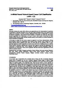
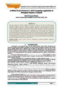
6. SIMLATION RESULTS In this part, simulations are investigated with a 1.5MW DFIG connected to a 398V/50Hz grid (appendix), by using the MATLAB/SIMULINK software. The proposed control strategy (ANN-DPC) is simulated and tested in both cases: fixed wind speed, and variable wind speed. A. Fixed wind speed In this case, the wind speed is maintained constant at its nominale value (12.25m/s), we initial simulation with various active and reactive powers steps in nominal regime of DFIG. The negative sign “-“ refers to the generation of active power and to the absorption of reactive power. The DFIG is driven from the subsynchronous speed (1000rpm) to the supersynchronous speed (2000rpm) by crossing the synchronous speed (1500rpm). The sampling period of the system is 10μs. All simulation results are show in Fig. 11, from top to bottom, the curves are active power (Ps), reactive power (Qs), power factor (PF), stator currents and rotor currents.
15
DPC control based artificial neural networks of DFIG
Fig. 11 – ANN-DPC strategy simulation results in fixed wind speed operation.
15
16
Youcef Djeriri, Abdelkader Meroufel, Ahmed Massoum
16
The simulation results in Fig. 11, under nominals conditions of operation show that the designed ANN-based DPC strategy is able to provide good performance. The decoupled control of active and reactive power is achieved and powers responses follow their reference values well. The reactive power reference will be set to zero (Qs*=0MVAR) to ensure a unity power factor (PF=1) at the grid side, in order to optimize the generated stator active power quality. By consequence, the stator current has a negligible ripple and a nearly sinusoidal wave. In the other hand, the changeover from subsynchronous to supersynchronous speed crossing the synchronous speed is observed to be smooth without any transients in the rotor current waveform. B. Variable wind speed In this section, simulations are performed with a varibale wind speed, with a mean value of 8.2m/s. In this case, a battery storage unit is included to the DC bus to provide a constant active power to the grid for all wind conditions. In high wind speed conditions, the DFIG provides energy to the network and refills the storage unit whereas in insufficient wind conditions, the storage unit allows compensating the lack of energy. This is a very useful operation for wind turbine grid connection. The pitch control achieves the maximum efficiency of the turbine. It is also possible to turn off the turbine when wind speed is too large to prevent any mechanical damage. For a given wind speed, the power reference is calculated and subtracted from the constant power injected to the grid to fix the power reference for the storage unit. This power can be positive or negative according to wind speed conditions. The power can be positive or negative if the generator performs at hyper or hypo synchronous conditions and when the storage unit absorbs power from the wind turbine or provides power to the grid. The storage unit is controlled in power for charge and discharge, and the power stored in the battery is calculated by: Pstored Ps 0.75 MW
(32)
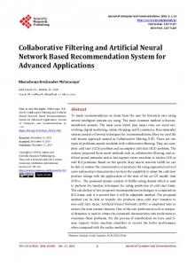
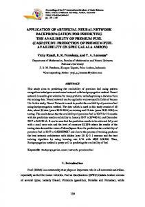
And the power injected to the grid is given by the expression: (33) Pgrid Ps* Pstored Where Ps and Ps are the produced and reference active power respectively. Fig. 12 present simulation results for a 1.5MW DFIG associated with a 0.75MW storage unit. The wind turbine is also supposed to inject a constant power of 0.75MW into the grid for all wind conditions. The ANN-DPC strategy is always simulated at 10μs sampling period. *
17
DPC control based artificial neural networks of DFIG
Fig. 12 – ANN-DPC strategy simulation results in variable wind speed operation.
17
18
Youcef Djeriri, Abdelkader Meroufel, Ahmed Massoum
18
In the Fig. 12, the active power of the DFIG follows the power reference calculated from the wind speed. This power is limited by the generator nominal power (1.55MW). Simulation results for active power of the DFIG demonstrate the impossibility of generating a constant active power equal to 0.75MW under all wind speed conditions. For this reason, batteries are included to maintain a constant active power at the grid side; so batteries correspond to a positive power when charging and a negative power when feeding the grid. The produced active power is kept constant (0.75MW) for all wind conditions. This corresponds to the sum of the DFIG and storage unit powers. Consequently, this wind energy conversion system can be assimilated as a constant generator for active power. The reactive power is correctly regulated and it’s always mainained to zero with an aim of keeping a unit power factor at the grid side, and a slight modification to the DC-bus voltage is obtained. So that by using the ANN-DPC technique a decoupled control of active and reactive power is achieved even in the case of the variable wind speed. 7. CONCLUSION The DFIG is nowadays a popular choice for wind energy conversion systems. This popularity is mostly due to its ability for large variable speed drive. In this paper, a direct power control strategy using a controller based on an MLP artificial neural network has been presented. This technique has been used for reference tracking and decoupling of active and reactive powers exchanged between the stator of the DFIG and the grid by controlling the rotor converter. Firstly, the model of the DFIG has been associated with a wind turbine model controlled with MPPT strategy. The whole system thus constituted permits to control the DFIG at subsynchronous and supersynchronous speeds. Then, stator field oriented technique is applied to simplify the model of the the DFIG in study state. After that, DPC approach is presented and combined with the MLP-ANN controller to allows the control of the stator powers of the DFIG by the direct manipulation of rotor voltages without the need for current controllers and requiring only a single controller. The simulation results have shown the effectiveness of the proposed strategy (ANN-DPC) in attending changes of the active and reactive power with unity power factor in tow cases, fixed and variable wind speed. However, the incorporation of batteries or other energy storage device in the DC-link must be necessary to enables a temporary storage of energy and therefore, the ability to provide constant active power injected to the grid, which is both deterministic and resistant to wind speed fluctuations.
19
DPC control based artificial neural networks of DFIG
19
APPENDIX : Table 1 Wind turbine parameters
Blade radius, R Number of blades Gearbox ratio, G Moment of inertia, J Viscous friction coefficient, fr Cut-in wind speed Cut-out wind speed Nominal wind speed, v
35.25 m 3 90 1000 Kg.m2 0.0024 N.m.s-1 4 m/s 25 m/s 16 m/s
Table 2 Doubly fed induction generator parameters
Rated power, Pn Stator rated voltage, Vs Rated current, In Rated DC-Link voltage UDC Stator rated frequency, f Stator inductance, Ls Rotor inductance, Lr Mutual inductance, Lm Stator resistance, Rs Rotor resistance, Rr Number of pair of poles, p
1.5 MW 398/690 V 1900 A 1200 V 50 Hz 0.0137 H 0.0136 H 0.0135 H 0.012 Ω 0.021 Ω 2
REFERENCES 1. M.H. Ahmed, K. Bhattacharya, M. M. A. Salama, Stochastic Unit Commitment with Wind Generation Penetration, Elect. Power Compon. Syst 2012; vol. 40, no. 12, pp. 1405–1422. 2. World Wind Energy Association (online) , available: http://www.wwindea.org. 3. Ozbek M, Rixen DJ, Erne O, Sanow G. Feasibility of monitoring large wind turbines using photogrammetry. Energy 2010; vol. 35, pp. 4802-4811. 4. A. Petersson, Analysis, modeling and control of doubly fed induction generators for wind turbines, PhD. thesis, Champers University of Technology, Sweden, 2005. 5. S. EL Aimani, B, François, F. Minne, and B. Robyns, Modelling and simulation of doubly fed induction generators for variable speed wind turbines integrated in a distribution network” 10th European conference on power electronics and applications, Toulouse, France, 2-4 September 2003. 6. L.M. Fernandez, C.A. Garcia, F. Jurado, Comparative study on the performance of control systems for doubly fed induction generator (DFIG) wind turbines operating with power regulation. Elsevier, Energy, 2008, vol. 33, pp. 1438-1452.
20
Youcef Djeriri, Abdelkader Meroufel, Ahmed Massoum
20
7. I. Boldea, Electric Drives, Taylor & Francis, 2006. 8. S. Muller, M. Deicke, R. W. De Doncker, Doubly fed induction generator systems for wind turbines,” IEEE Ind. Appl. Mag., vol. 17, no. 1, pp. 26-33, May–Jun. 2002. 9. R. Pena, J. C. Clare, and G. M. Asher, Double fed induction generator using back-to-back PWM converter and its application to variable-speed wind-energy generation, Proc. IEE B Electr. Power Appl., vol. 143, no. 3, pp. 231-241, May 1996. 10. Y. Zhou, P. Bauer, J.A. Ferreira, and J. Pierik, Control of DFIG Under Unsymmetrical Voltage Dip, IEEE Power Electronics Specialists Conference, pp. 933-938, 2007. 11. J. Jang, Y. Kim, D. Lee, Active and Reactive Power Control of DFIG for Wind Energy Conversion Under Unbalanced Grid Voltage. CES/IEEE 5th Int. Power Electronics and Motion Control Conf., pp.1-5, 2006. 12. B. Hopfensperger, D.J. Atkinson and R. Lakin, Stator-Flux-Oriented Control of a Doubly-Fed Induction Machine with and without Position Encoder, IEE Proceedings -Electric Power Applications, vol. 147, no. 4, pp. 241-250, 2000. 13. Xu, L., Wang, Y., 2007. Dynamic modeling and control of DFIG based wind turbines under unbalanced network conditions, IEEE Trans. on Power Syst., vol. 22, no. 1, pp. 314-323. 14. A. Tapia, G. Tapia, J. X. Ostolaza, and J. R. Sáenz, Modeling and control of a wind turbine driven doubly fed induction generator, IEEE Trans. on Energy Conversion, pp. 194-204, June 2003. 15. G. Tapia, A. Tapia, and J. X. Ostolaza, Proportional–integral regulator based approach to wind farm reactive power management for secondary voltage control, IEEE Trans. Energy Conversion, vol. 22, no. 2, pp. 488-498, June 2007. 16. M. Yamamoto, O. Motoyoshi, Active and reactive power control for doubly-fed wound rotor induction generator, IEEE Transactions on Power Electronics, vol. 6, no. 4, October 1991, pp. 624-629. 17. Y. Djeriri, A. Meroufel, A. Massoum and Z. Boudjema, A comparative study between field oriented control strategy and direct power control strategy for DFIG, Journal of Electrical Engineering, JEE, Romania, vol.14, no.2, pp. 169-168, June 2014. 18. I. Takahashi and T. Noguchi, A new quick-response and high-efficiency control strategy of an induction motor, IEEE Trans. Ind. Appl., vol. IA-22, no. 5, pp. 820-827, October 1986. 19. M. Depenbrock, Direct self control of inverter fed induction machines, IEEE Trans. Power Electron., vol. 3, pp. 420-429, 1988. 20. T. Noguchi, H. Tomiki, S. Kondo, and I. Takahashi, Direct power control of PWM converter without power-source voltage sensors, IEEE Trans. Ind. Applications., vol. 34, pp. 473-479, May/June 1998. 21. R. Datta, V. T. Ranganathan, Direct power control of grid-connected wound rotor induction machine without rotor position sensors, IEEE Trans. Power Electron, vol. 16, no. 3, pp. 390-399, May 2001. 22. L. Xu, P. Cartwright, Direct active and reactive power control of DFIG for wind energy generation, IEEE Trans. Energy Convers, vol. 21, no. 3, pp.750-758, Sept. 2006. 23. Y. Djeriri, A. Meroufel, A. Massoum and Z. Boudjema, Direct power control of a doubly fed induction generator based wind energy conversion systems including a storage unit, Journal of Electrical Engineering, JEE, Romania, vol.14, No.1, pp. 196-204, March 2014. 24. C. Belfedal, S. Moreau, G. Champenois, T. Allaoui and M. Denai, Comparison of PI and Direct Power Control with SVM of Doubly Fed Induction Generator, Istanbul University, Journal of Electrical and Electronics Engineering, vol. 8, no. 2, pp. 633-641, 2008. 25. M. V. Kazemi, A. S. Yazdankhah, H. M. Kojabadi, Direct power control of DFIG based on discrete space vector modulation, Elsevier, Renewable Energy, vol. 35, no. 5, pp. 1033-1042, May 2010.
21
DPC control based artificial neural networks of DFIG
21
26. G. Abad, M. A. Rodriguez, J. Poza, Two-level VSC-based predictive direct power control of the doubly fed induction machine with reduced power ripple at low constant switching frequency, IEEE Trans. Energy Convers., vol. 23, no. 2, pp. 570-580, June 2008. 27. D. Zhi, L. Xu, B. W. Williams, Model-Based Predictive Direct Power control of Doubly Fed Induction Generator, IEEE Trans.on .Power Electronics, vo1.25, no.2, pp. 341-351, February 2010. 28. M. V. Kazemi, M. Moradi, R. V. Kazemi, Minimization of powers ripple of direct power controlled DFIG by fuzzy controller and improved discrete space vector modulation, Elsevier, Electric Power Systems Research, vol. 89, pp. 23-30, March 2012. 29. M. Pichan, H. Rastegar, M. Monfared, Two fuzzy-based direct power control strategies for doubly-fed induction generators in wind energy conversion systems, Elsevier, Energie, vol. 51, pp. 154-162, February 2013. 30. R. A. De Marchi, F. J. Von Zuben, E. Bim, A Neural Network Approach for the Direct Power Control of a Doubly Fed Induction Generator, XI Brazilian Congress of Power Electronics, IEEE, vol. 1, pp.38-43, Natal, Brasil, Sept. 2011. 31. S. Heier, Grid Integration of Wind Energy Conversion Systems, John Wiley and Sons, 1998. 32. K. Hornik, M. Stinchcombe, H. White, Multilayer feed forward networks are universal approximators, Neural Networks, vol. 2, pp. 359-366, 1989. 33. P. Werbos, Beyond regression: new tools for prediction and analysis in the behavioral sciences, PhD thesis, Cambridge, MA: Harvard University Committee on Applied Mathematics, 1974. 34. D. Kukolj, F. Kulic and E. Levi, Design of speed controller for sensorless electric drives based on ai techniques: a comparative study”, Artificial Intelligence in Engineering, vol. 14, pp. 165- 174, 2000. 35. J.J. Moré, The Levenberg-Marquardt Algorithm: Implementation and Theory, Numerical Analysis, ed. G. A. Watson, Lecture Notes in Mathematics 630 , Springer Verlag, pp.105-116, 1977. 36. M.T. Hagan, M. Menhaj, Training feedforward networks with the Marquardt algorithm, IEEE Trans, Neural Networks, vol. 5, no. 6, pp .989-993, 1994.