Proceedings of the ASME 2008 International Design Engineering Technical Conferences & Computers and Information in Engineering Conference IDETC/CIE 2008 August 3-6, 2008, Brooklyn, New York, USA
DETC2008-49375 DISASSEMBLING SYSTEM OF LARGE SCALED STRUCTURE CONSIDERING SAFETY, ENVIRONMENTAL IMPACT, AND ECONOMIC EFFICIENCY Tsuyoshi Koga∗ Department of Systems Innovation
Motoyuki Matsubara Department of Environmental & Ocean Engineering
Kazuhiro Aoyama Department of Systems Innovation Maritime Innovation (Tsuneishi Shipbuilding) Laboratory School of Engineering The University of Tokyo, 7-3-1 Hongo, Bunkyo-ku, Tokyo 113-8656 Japan. ABSTRACT When a ship finished its lifetime, its hull is scrapped and recycled. Presently, the ships are scrapped mainly on the lessdeveloped countries. The ship recycling in developing countries often comprises hazardous and environmentally damaging processes, and has developed into a serious problem from the viewpoint of realizing an international resource recycling society. It is predicted that over the next few years, disassembly of substandard ships that do not fulfill safety guidelines, such as single-hull tankers, will increase rapidly. Hence, economical, safe and environment-friendly ship disassembly processes are strongly desired. This paper proposes a planning method for the safe, economical, and environment-friendly ship disassembling process. The planning method derives an optimal disassembly process by considering safety, cost, and environmental impact. In order to develop this disassembling system, this paper addresses (1) a model of the scrapped ship, the facility, the field, and (2) a disassembling process models considering the hull, factory, and operations and (3) a planning method of disassembling process to achieve both of the safety and environmental cost. Based on the models and methods, a evaluation function that considers safety, disassembling cost, and environmental impact is proposed. An example of a disassembling process planning on an actual ship-hull structure is shown in this paper. A best planning result contains less unstable state of hull block, includes a lot of parallel tasks, and utilizes the best performances of equipments of the factory. The proposed system can provide not only safety information during disassembly to developing countries but also an economical disassembly equipment assignment plan to developed countries. ∗
1 INTRODUCTION This study focuses on the issue of realizing an international resource recycling society that can overcome ‘environmental problems’ to ensure the coexistence of humans and the environment and establish new relationships between them. Significant contributors to the formation of an international resource recycling society are ships, which are responsible, to a great extent, for material distribution. Japan is currently at a standpoint from where it must think about the role of ships in this regard. This is because in 2004, sea trade in Japan accounted for 15.4% of the worldwide marine transport. Moreover, the country, together with China and South Korea, is responsible for 86.8% of new ship-building activities. Consequently, Japan now has a mission: to promote the formation of an international resource recycling society through sustainable development. 1.1 REALIZING AN INTERNATIONAL RESOURCE RECYCLING SOCIETY: There exist three summaries regarding the realization of an international resource recycling society [1]. The first concerns a principle of preventing environmental pollution. More specifically, the principle deals with constructing routes for resource circulation for appropriate processing of resources such as waste (system), preventing environmental pollution in all system processes and confirming the circulation resources moving within the system. In effect, the principle seeks to ensure the traceability of circulation resources by employing a rule such as those outlined in the Basel Convention. The second summary concerns the promotion of waste management and recycling industries, which will definitely
Associate Professor and author of correspondence, Phone: +81-3-5841-6506, Fax: +81-3-3815-8364, Email:
[email protected].
1
Copyright © 2008 by ASME
Table 1: Forecasted amount of material generated by ship recycling year Steel Copper Zinc Special bronze Machinery Electrical equip Joinery Minerals Plastics Liquids Chemic./gases Other misc.
(Unit:million ton) 2007 2008 2009 2010 2011 2012 2013 2014 2015 4.81 5.34 4.98 12.3 4.12 3.83 3.99 3.93 4.68 0.002 0.002 0.002 0.003 0.001 0.001 0.001 0.001 0.001 0.002 0.003 0.002 0.005 0.002 0.002 0.002 0.002 0.002 0.002 0.003 0.002 0.005 0.002 0.002 0.002 0.002 0.002 1.11 1.2 1.13 2.5 0.95 0.89 0.91 0.89 1.03 0.25 0.26 0.25 0.49 0.21 0.2 0.2 0.19 0.22 0.37 0.41 0.38 0.87 0.32 0.3 0.31 0.3 0.35 0.09 0.09 0.09 0.14 0.8 0.7 0.7 0.7 0.8 0.05 0.06 0.05 0.1 0.05 0.04 0.04 0.04 0.05 0.11 0.12 0.12 0.31 0.09 0.09 0.09 0.09 0.11 0.002 0.002 0.002 0.005 0.002 0.002 0.002 0.002 0.002 0.1 0.1 0.1 0.2 0.08 0.08 0.08 0.08 0.09
Ship Cost
The formula that provides a basic economy evaluation of a ship-recycling process is shown in the mathematical expression (1) [3].
Labor Cost
Other Cost
350 300 250 USD/LDT
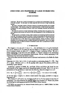
Economic value = (usable value of recycled material) – ((scrapped ship cost) + (disassembly cost)) (1) Figure 1 shows an example of the expenses and cost breakdown for ship-recycling sites in Bangladesh, China and the Philippines (Japanese company) [4].
200 150 100 50
Costs such as equipment cost, sub-material cost, environmental preservation cost and welfare cost are included under ‘Other Cost’. The cost of the scrapped ship is influenced not only by the characteristics of the ship, such as the tonnage year or ship type, but also by factors such as the collection material market, fare market or marine transportation market on the supply side and used ship market on the demand side [5].
0 BANGRADISH
CHINA
PHILIPIN(JAPANESE COMPANY)
Figure 1. Disassembly cost and its country-wise breakdown Ship Value(USD/LDT) Iron and steel scrap(USD/ton)
Light bars price(USD/ton)
400 350
Figure 2 illustrates the changes in the cost of ship scrap in recent years. The figure also shows the changes in the cost of steel in Japan; steel contributes to about 80% of the weight of a ship, but accounts for nearly 90% of the earnings from recycling [3].
300 USD
250 200 150 100
Based on this information, another expression, the below expression (2), can be formulated. The cost of disassembly plus the earnings per unit weight can be roughly estimated from this expression; the changes in this combined value are shown in Figure 3.
50 2003
2002
2001
2000
1999
1998
1994
0 1997
1.2. PROBLEM OF SHIP RECYCLING AND ITS CURRENT STATE: Component materials obtained from ship disassembly are recycled so that they can be used in industries where their demand is high. These materials are in the form of various metals, which are found in onboard equipment, articles, goods, etc.; however, the major material of construction—used in tankers and bulk carriers—on a merchant ship is steel. The amount of material generated by ship recycling is estimated from the ratio of the composition materials on a ship to the forecasted exhaust amount on scrapped ships (Table 1) [2].
On the other hand, ship recycling involves the handling of hazardous materials, and if appropriate safety measures are not undertaken, industrial accidents and environmental pollution will result. Moreover, the process of disassembly carries the risk of accidents due to negligence. In fact, on an average, 43 incidents of injury or death occur at the disassembly sites in Alang, which is located in the state of Gujarat in India (Table 2) [6].
1996
The third summary concerns enacting legislation by which waste management and recycling ability improvement are promoted. For such legislations to be successful, participant countries should extend mutual cooperation. In addition, they must form a system framework for an international resource recycling society, although a system suited to each country would be introduced into this framework based on the industrial establishments and circulation structures that are specific to each country.
× ((light bar price × 0.2) + (iron and steel scrap price × 0.8)) / 0.9) – (amount of ship scrap × unit price of ship scrap) [USD/LDT] (2) The changes shown in Figure 3 are for the Japanese shiprecycling industry; the recycled material price is determined by the domestic market in each country. From Figure 3, it is evident that it will be difficult for the ship-recycling industry to stabilise its earnings if the demand for recycled materials is high.
1995
ensure effective natural resource utilisation and appropriate waste processing, and the improvement in the ability of the international society to recycle. Thus far, waste management and recycling industries in Japan have improved the country’s recycling ability by enhancing efficiency and strengthened the economy through technological development and improved management. It is therefore important that Japan shares its experience in this field with other countries in order to contribute to the formation of an international resource recycling society.
Figure 2. Change in cost of recycled material and ship scrap
Scrap cost + Income = ((Amount of ship scrap × 0.8)
2
Copyright © 2008 by ASME
facilities are requested to fulfil the requirements of the convention (Figure 4).
scrap cost+income(USD/LDT)
100 0
subject step
-100 ship builder
-200
-400
ship owner requrement of ship
2003
2002
2001
2000
1999
1998
1997
1996
1995
1994
Figure 3. Change in the sum of the disassembly cost and the earnings per unit weight (earnings based on the domestic market in Japan)
flag state
recycling site
Table 2: Scrap volume generated and injury and death tolls in Alang, Gujarat, India
1997 1998 1999
scrap No. of breaking volume (LDT) ship 347 2452019 361 3037882 296 2752414
No. of w orkers 25000 25000 25000
Fatal Deaths incidents 31 18 26
46 26 30
No. of fatal incidents 3 24 28
Injuries 23 41 36
recycling nation
Total No. of incidents 34 42 54
1.3. TRENDS IN SHIP-RECYCLING-PROBLEM: In recent years, although many ships have been recycled in the South Asian region, as discussed above, industrial injury and oceanic environmental pollution caused at ship disassembly sites continues to be a problem. Therefore, ship stakeholders have begun taking interest in the ship-recycling problem from various viewpoints. One major concern was whether a ship scheduled for disassembly was a waste item according to the guidelines provided by the Basel Convention. To address this concern, the stakeholders opened a discussion to decide the parameters that should be complied with based on the guidelines adopted by the IMO, ILO and UNEP . In February 2005, a meeting of the First Joint Working Group (JWG1) of the IMO, ILO and UNEP was convened to trace a direction of action and decide the future work plan for each organization. At the 53rd Maritime Environment Preservation Committee (MEPC53) meeting of the IMO held in July 2005, a decision to initiate efforts toward adopting a new international convention (ship-recycling convention) that included compliance parameters was taken. Subsequent to this meeting, discussions on the convention parameters were initiated; for example, in December 2005, the IMO/ILO/UNEP guidelines were subjected to a comparative study in JWG2, and in March 2006, Norway proposed a convention draft [7] that was discussed in MEPC54. The outline of the convention draft proposed by Norway in MEPC54 is as follows. The objectives of the convention were to first decrease the harmful effects of ship-recycling activities on marine environments and worker health, then minimize these effects and ultimately, eliminate them completely. The convention also aimed to safeguard ship and worker health and maintain a safe environment through regular servicing of ships. In order to achieve these aims, ships and recycling
requirement of site
recycling site
shipping and mentenance
prepare of recycling
Use prohibition/ limitation of hazardous materials Onboard inventory of hazardous materials
-300
-500
Year
design and construction
Update of inventory Creation of inventory
Select of licensed yard Planning of shipping to end Planning of gas free Notice to flag state/ recycle nation report verification of finish last investigation/ prepear for disassembling planning of ship recycling with owner protestation of disassembling licenced site apropriate criterion accept only ship appropriate convention planning management of recycle site ensuring of gas free preventing of accident to people or nation safety and environmental removing hazard materials prepearing to emergency safety management and education for worker report accident
Figure 4. Requirements that ship stakeholders must fulfil, as proposed by the ship-recycling convention 1.4. PURPOSE OF THE STUDY: In this study, the construction of a planning system for ship hull disassembly is proposed as a solution to the problem of ship recycling. In this study, the ship-recycling problem is regarded as a hindrance to realizing an international resource recycling society. Therefore, a solution to this problem is put forth with the objective being the realization of a recycling society. Once the proposed solution is presented, if the revised shiprecycling problem is compared with that described in section 2, a plan to improve the onsite recycling capability could be drawn and prove to be an important strategy to be laid down in the ship-recycling convention. As explained in section 4, it is difficult to preserve the environment and ensure labour safety if extreme measures are adopted to control the disassembly cost by a sudden increase in ship scrap cost. Moreover, at some recycling sites, the amount of ship scrap exceeds the processing capacity. This reduces the disassembly cost significantly; however, environmental preservation and labour safety are ignored in the process. This scenario also presents the problem of illegal disposal: intermediate processing facilities claim low processing expenses, thereby gaining an unfair advantage and occupying the market without having sufficient treatment capability. To arrive at a fundamental solution to the illegal disposal problem, healthy competition among intermediate treatment facilities that have sufficient waste treatment capability must be encouraged once their individual processing capacities are verified. In the same manner, if shiprecycling sites strive to achieve efficient disassembly together with appropriate waste treatment capability or processing
3
Copyright © 2008 by ASME
commission capability, the attitude of the shipping industry with regard to the sale of ship scrap could change.
priorities of cutting tasks is defined as a priority link in the graph model of ship structure.
Based on the above-mentioned point, it can be said that a plan to improve the onsite recycling capability and the objectives of the ship-recycling convention complement each other. There arises, therefore, a necessity for good plans to increase onsite capabilities, because the objectives of the convention would take effect and claim greater authority only once these plans are steadily implemented.
Start
Step1: Removing hazardous materials Step2: Planning for division plan Step3: Planning of disassembling process Step4: Disassembling Step5: Reuse / recycle materials A basic concept of recycling flow is shown in Figure 5. First input is design data of ship-hull (shape and structure), collection parts and hazardous materials. The output in this system is data of disassembling object. Based on the factory information, the planner input a stage / equipment of recycling site. The planning system calculates a plan for disassembling process of ship. Collection parts Ship-hull £30
Hazardous materials
£20 £10
A plan for disassembling process of ship
£-40
Planning for dividing of ship
input stage/ equipment of recycling site
Cleaning
A
A
B
B
Dividing
C
B
B C A
B
C A
B
C A
C
B
A
A comparison of two different disassembling processes is shown in Figure 7. A disassembling structure is same, but the sequence of operations is different. The disassembling process A contains more cutting works on high place than the disassembling process B. The cutting work on high place is dangerous, hence the disassembling process B is more safer than disassembling process A. A cutting cost of the disassembling process B is more effective and cheaper than the disassembling process A, because the parallel work is able and expencive cutting on dock is less. A rotating cost and moving cost also estimated to be compared. The best disassembling process is searched based on total safety and economical cost. The two different disassembling processes are worst and best case of example 1 in figure 10. The disassembling process is defined as a sequence of the operations such as cutting, conveying, and rotating. The operation is operated by the worker and equipment such as crane. The ship module is conveyed to a stage in the factory such as dock and land. The ship is divided based on the operation by the equipment at the stage. The relationship between the sequence of operations, stage, equipment, and ship module is shown in Figure 8. Figure 8 represents a model of disassembling process in this paper.
Planning for disassembling process of ship
operation
stage
equipment
module
cutting
Dock
Cutter A
length height Base area
conveying
Crane A
weight
rotating
Crane B
weight
Land
Cutter B
length height
Dock
Cutter A
Figure 5 System Concept of Ship Recycling Flow A disassembling object and cutting restrictions is represented based on graph model. Figure 6 represents the graph model of a disassembling object and operation processes of prior cutting, cleaning, and dividing. A hazardous material to be removed is defined as in the ship structure. The hazardous material cannot be removed on the ship, hence prior cutting must be planned before cleaning process. After the cleaning, dividing can be operated and finally we can get the reusable part A and B. The
B
Figure 6 Graph representation of prior cutting, cleaning and dividing
output
data of disassembling object
Prior cutting
A A
2 FORMULATION AND QUANTIFICATION OF SHIP DISASSEMBLY 2.1 Planning method for the safe and effective ship disassembling process A ship recycling flow proposed in this paper mainly focuses on a planning for disassembling process f ship. An input of this system is data of disassembling object, stage, and equipment of recycling site. An output of this system is a plan of disassembling process considering safety, cost and environmental impacts. The overall planning step of the ship recycling is as follows:
Black line must be cut prior to Gray line
Priority link
Hazardous materials
cutting
BA BA
length height
Figure 8 Model of disassembling process The disassembling process contains two phases: a block disassembling and part disassembling. Figure 9 shows the
4
Copyright © 2008 by ASME
Worst Solution:
Best Solution
Disassembling Process A
Disassembling Process B rotating
rotating
Parts ABCD rotating Cutting work on high place
Part C
3times >2times
Parts AB
cutting
Parts CD
rotating Parallel work is
Move to plant
rotating
Cutting on Dock
5
3 rotating cutting
Cutting in plant
rotating Part B
Part D
rotating
rotating
unable able
Part A
Move to plant
0
2
Part A
Part B
rotating cutting Part C
Part D
Figure 7 Comparison of Best and worst disassembling process representation model of ship, block, and part. The part division is represented as a cutting of graph which node is collect part and link is cutting line. The block means the collection of the part. The block is represented as a contracted graph of parts. The ship is represented as a graph which node is block and link is the connection of block. A multi-stage disassembling process planning can be calculated based on the block and part model of the ship. Ship
Part
Basic requirements for recycling ship scrap include universal principles borrowed from those presented in the convention draft, such as ‘drawing up ship-recycling plans’ and ‘drawing up ship-recycling site management plans’. For instance, there are close relationship between safety, quality and efficiency in production process. Reasonable cooperation of those elements causes ultimately achievement of excellent management’. In this study, a ‘disassembly planning system’ was constructed based on such principles. Contents of the system mean formulation of the capability, and results of evaluation with the system mean quantification of the capability.
Link: Cutting line
First, let us explain the basic concept of the disassembly planning system proposed in this study. Disassembly can be understood as the process of dividing a scrapped ship into various materials, where the materials are connected by a set of relations. Differences in the division process manifest in the form of differences in the total working time (TWT) based on the setting conditions (Figure 10).
Block Parts division
Block division
Cut link: Block connection
Weight Limit
Node: Collect Part
Contract Contracted Link: Cut line inside Block
Ship representation
Contracted Graph
study, we propose the introduction of computers into the task of recycling ship scrap since shipbuilding also involves the use of computers [9].
Figure 9 Hierarchical disassembling planning 2.2 Safety and cost in disassembling process The plan to improve the onsite recycling ability was intended as a strategy that could solve the ship-recycling problem while complementarily meeting the objectives of the ship-recycling convention. However, in order to form a good plan to improve the capability of actual recycling sites, the site capability must be formulated and quantified. Conventionally, the process of formulation and quantification for deriving a good capability plan are performed by information processing, which can be carried out based on worker experience rules and manual calculation [8]. In this
5
Copyright © 2008 by ASME
O
A2
A5
A4
A1
B1
A6
A3
B2
B4
B3
Figure 12. Solution space of example 1 (ten processes)
C1 【configuration constraint】 convey:time cut stage:time 4b→1b:1min/b 4b:5min/line 4b→2b:3min/b 3b:3min/line 4b→3b:5min/b 2b:1min/line 3b→1b:1min/b 3b→2b:3min/b 2b→1b:1min/b 【working time】 process cu co co cu cu O → A1 → B1 → C1 10 6 6 1 1 O → A1 → B2 → C1 10 6 6 1 1 O → A2 → B3 → C1 10 6 6 1 1 O → A2 → B4 → C1 10 6 6 1 1 O → A3 → B1 → C1 10 15 1 3 O → A3 → B4 → C1 10 15 1 3 O → A4 → B2 → C1 10 15 1 3 O → A4 → B3 → C1 10 15 1 3 O → A5 → B1 → C1 10 15 1 3 O → A5 → B3 → C1 10 15 1 3 O → A6 → B2 → C1 10 15 1 3 O → A6 → B4 → C1 10 15 1 3
※b=block ※cu=cut ※co=convey
co co cu 1 1 1 1 1 1 1 1 6 1 1 6 1 1 6 1 1 6 1 1 6 1 1 6 1 1 6 1 1 6 1 1
co co all 1 1 28 1 1 28 1 1 28 1 1 28 1 1 39 1 1 39 1 1 39 1 1 39 1 1 39 1 1 39 1 1 39 1 1 39
Figure 10. Division patterns and differences in TWT in the division order
Figure 11. Four-part module (example 1)
3 DISASSEMBLY PLANNING SYSTEM The system was coded in Smalltalk based on an existing system [10] by referring to a block division system [11]. 3.1 CREATION OF PROCESSES: In this system, a scrapped ship is considered as a module made up of parts that are finally collected, and links between these parts are formed and input into the system beforehand. Further, the disassembling capability is defined by stages where ship is disassembled and disassembling operations. The system will now be explained by referring to the example module shown in Figure 11. This module is composed of four parts and five links, and it bears a constraint: link UppDK/1–Shell/2 must be cut before link UppDK/1–front/1 (gray arrow). Such constraints can be used to determine which components can be removed as blocks. Based on the above-mentioned conditions, ten types of processes for division from the whole ship to its component parts can be ascertained (Figure 12). We now explain the creation of processes. First, a single process is created. Modules for this process are then created; these include all combinations of the subsequent modules composed of three parts. A module that cannot exist owing to a constraint is not created. Next, a module is randomly selected from the created modules, and subsequent modules of the selected module are created. If it reaches ship through repeating these, and the first process is made. Since then, it doesn't calculate again when selected module was selected in the past and next modules of the module are made. 3.2 EVALUATION OF EACH PROCESS: The optimal process is selected from the created processes through absolute judgment and comparative assessment. Absolute judgment assesses feasibility, while comparative assessment compares productivity with the degree of environmental preservation and labour safety. The evaluation processes will be described by referring to the example shown in Figure 13. 3.2 (a) Absolute judgment When a process is created, the availability of a module is assessed each time a new module is created. Availability implies that a module has a bearing area. The bearing area is the largest of six sides of a module (along the vertical direction). Further, it is assumed to be the area of the side that includes gravity centre of the module with a margin. However,
6
Copyright © 2008 by ASME
thickness of parts are excluded and when there are two or more sides, enclosed these area is included (Figure 14). If the bearing area is 0, the module has false availability (Figure 15). A module with false availability is excluded from the process. The process is assigned a false feasibility and excluded from the best candidates, which are determined by the total working hours; this exclusion is done by assigning the total working hours for the excluded process as infinity. This evaluation of the division plan is called absolute grading.
Figure 15. Unstable Posture of Module
3.2 (b) Comparative assessment: If the absolute judgment of a process produces a true result, a stage and operation are allocated to each module. The stage is set as the location where the bearing area of the module is installed. Each module makes it rotate to convey from stage of parent module and to set it up by steady posture before it is divided. Conveying and rotating equipment are allocated to each module. The allocation is performed based on a comparison of the weight of each module and the maximum handling weight of the equipment: the module weight must not exceed the maximum handling weight of the equipment. If paint is present on the cutting surface, it is peeled off before cutting. For the cutting and peeling operations, equipment allocated to each stage is allocated to each module. The TWT of a process is calculated by the following expression. Total wt = ∑ (U wt × Wmodule ) + ∑ (U wt × RA) + ∑ (U wt × Lcutting line × CH)
(A) Ship Hull Structure
(3)
where Totalwt: total working time, Uwt: unit working time, CH: coefficient corresponding to height, Wmodule: weight of module, Lcutting line: cutting line length, RA: rotation angle.
The TWT for each module of a process is calculated. A positive score is awarded to each module if its TWT is lower than that of the previous process; however, if the TWT is greater, a negative score is awarded. If the TWT for the first process is not available, a positive score is awarded. Because this awarded score is fed back for module selection, the process is extended each time the extent of selection is increased. As a result, the chances of selecting a module that has a high score increase. Moreover, determining a good process, for which the TWT is low, and a bad process, for which the TWT is high, lead to reinforced learning (Figure 16). (B) Parts Members Connection Network
Figure 13. Change in cost of recycled material and ship scrap
(a)
(b)
A parent module is created when two modules (children) and relationships (cut links) between them are formed as the processes advance and number of modules increases. Each process can thus be understood as a module tree where a node divides into two branches, which end in a leaf. The number of nodes in the route that passes through the most number of nodes is considered as the depth of the module tree. The efficiency obtained by the mathematical expression (4) is multiplied with the TWT because it is considered that it is higher probability of parallel work as depth of the plan is shallow. I env = ∑ ((RA + CE ) × Wmodule ) + ∑ (CWS × (Lcutting line + Aws ))
Figure 14. Stable Posture of Module
…… (5)
7
Copyright © 2008 by ASME
Hazard = ∑ ((RA + CE) × Wmodule ) + ∑ (CH × Lcutting line ) (6) + ∑ (CWS × Aws ) where CH: coefficient corresponding to height, Wmodule: weight of module, Lcutting line: cutting line length, RA: rotation angle, Ienv: environmental impact, Aws: area of work space, CE: coefficient corresponding to equipment, CWS: coefficient corresponding to work space.
Figure 16. Reinforced learning curve (example1) Table 3: Equipment and workshops at the recycling site operation No.
cutting peeling conveying
rotating
1 2 3 4 1 1 2 3 4 1 2 3 4
unit workin g time AgedWorker 15 CuttingMachine 5 YoungWorker 10 YoungWorker2 7.5 Men 35 CraneA 5 CraneB 15 Lorry 10 MenA 20 Crane1 5 Crane2 15 PowerHand 10 MenHand 20 name
stage
max weight
Dock PlantA,B,C LandA,B IsolationP IsolationP Passageway Passageway Passageway Passageway Warehouse Warehouse Warehouse Warehouse
450 80 180 30 450 80 180 30
substructures. The main structure containing the substructures can be used as a means to decrease the computational complexity of optimization (Figure 18). A main structure is identified by a comparatively long cutting link in the entire structure and it is an indispensable component that forms a lump in the whole structure. A substructure is identified by a connection with a component that constitutes the main structure. Therefore, the substructure could have an embedded form, enclosing another substructure within it. A scrapped ship that has a massive structure can be divided based on the length of the cutting link. Considering the influence of a cutting link on the working time, a short cutting link can be neglected in a module, while a long cutting link should be included. The optimum result can thus be obtained faster by simplifying the model through contraction. In this case, model contraction and the inclusion of the main structure and its substructures reduced the number of parts and links from 41 to 18 and from 145 to 21, respectively (Figure 19). 4.2 CALCULATION RESULT: Next, 2000 processes of the contracted model were calculated. Processes with the lowest and highest TWTs are shown in Figure 20 and 22, respectively. A part of the module tree for the lowest and highest TWT processes are shown in Figure 21 and 23, respectively. 4.3 DISCUSSION: The semi-best process is a process that it divides by the limit size where components can be moved from Dock to Land. It means that it is not divided small on the Dock. Furthermore, improving the efficiency in this manner will contribute to ensuring labour safety and environmental preservation. In this case, the efficiency improving mainly depends on the decreases of a cutting work time. In conclusion, it is considered that drawing up a disassembly plan to improve the cutting efficiency will enable the formation of a plan to improve the onsite recycling capability.
name Dock Land Plant
space area length height weight operation equipment #open 66543 1000 66543 1000 cutting 1 #open 1000 40 50 400 cutting 3 #closed 10 10 20 100 cutting 2 cutting 4 IsolationP #clean 800 25 35 200 peeling 1 Passageway #open 66543 1000 66543 1000 conveying 1,2,3,4 Warehouse #closed 1000 1000 1000 1000 rotating 1,2,3,4
4 APPLICATION TO HULL STRUCTURE The application of the proposed system to an assumed shiprecycling site will now be illustrated. The equipment and workshops at the recycling site are set as shown in Table 3, and the item to be disassembled is a component of the ship (Figure 17). 4.1 DECREASING COMPUTATIONAL COMPLEXITY: There could be thousands of parts of a ship that can be classified as massive structures. The hull is one such part that can be considered to be a main structure containing
8
Copyright © 2008 by ASME
(A) Ship Hull Structure
(A) Ship Hull Structure
(B) Parts Members Connection Network Figure 17. Ship component (41 parts, 145 links)
(B) Parts Members Connection Network Figure 19. Model contracted to 18 parts and 21 links
Ship structure
Main structure
Sub structure
Figure 20. Processes with lowest TWT in the search range (semi-best process) convey cut convey
(B) Parts Members Connection Network Figure 18. Model contraction
rotate convey cut cut
Figure 21. Part of the semi-best process module tree
9
Copyright © 2008 by ASME
sites. We also expect that improving the recycling capability while keeping with the guidelines of the ship-recycling convention will solve the ship-recycling problem and contribute to the realization of an international resource recycling society. ACKNOWLEDGEMENTS We would like to acknowledge a support by a research grant of The Shipper's Association of Japan.
Figure 21. Process with highest TWT in the search range (semi-worst process)
cut rotate
convey
REFERENCES [1] International recourse cyclic working group of waste/ recycle panel on environmental board in council of industrial structure, ‘direct to realize sustainable recycling economic society’, October 2004 [2] European Commission / Directorate- General Energy and Transport, ‘Oil Tanker Phase Out and the Ship Scrapping Industry. A study on the implications of the accelerated phase out scheme of single hull tankers proposed by the EU for the world ship scrapping and recycling industry. Final’, June 2004 [3] Foundation ship dismantle project promote association, ‘report and reference about ship dismantle project promote’, March 1988
cut convey
cut convey
Figure 22. Part of the semi-worst process module tree 5 CONCLUDING REMARKS In this study, the realization of an international resource recycling society was considered as the objective and a solution to the ship-recycling problem based on its analysis was proposed. The solution can improve the onsite recycling capability while keeping with the guidelines of the shiprecycling convention. Further, it can improve the disassembly efficiency. Because the formulation and quantification of the onsite recycling capability was necessary to derive an improvement plan, a ship disassembly support system was constructed. In addition, specific equipment and a workshop were included in this system. The components of a ship were used as division units, and the TWT, Ienv and Hazard for each disassembly process were evaluated. Then, reinforced learning was employed to obtain the semi-best process of disassembly. We expect that once the proposed system has undergone improvements in the future, it can be applied to derive a plan to improve the recycling capability at actual ship-recycling
[4] International Federation for Human Rights, ‘Report/ Investigative Mission/ Where do the “floating dustbins” end up? Labour Rights in Ship breaking Yards in South Asia, The cases of Chittagong (Bangladesh) and Alang (India)’, December 2002 [5] Stavros Tsolakis, ‘Econometric Analysis of Bulk Shipping Markets Implications for Investment Strategies and Financial Decision-Making’, June 2005 [6] International Labor Office Geneva, ‘Sectoral activities programme An issues paper Worker safety in the shipbreaking industries’, February 2001 [7] Norway, ‘Proposal for a new legally-binding instrument on recycling of ships’, MEPC 54/3, December 2005 [8] Foundation ship dismantle project promote association, ‘Manual of ship dismantling’, March 1991 [9] Takanobu Osako, ‘Research of optimum method to shipbuilding’, Namura technical review No.9, September 1st 2006 [10] Yuya Uno, ‘master paper of 2002 propose and systemize of multi step approach to modularize design ’, The University of Tokyo Research of Engineering Environment and Ocean Engineering, February 3rd 2003 [11] Katsuhiro Aoyama, Syoji Takechi, Toshiharu Nomoto, ‘Basic research about block division aid system of shipbuilding CIM’, July 10th 2000.
10
Copyright © 2008 by ASME