Discovering a System Modernization Decision Framework: A Case Study in Migrating to Distributed Object Technology
Evan Wallace National Institute of Standards and Technology Manufacturing Engineering Laboratory Gaithersburg, MD, 20899, USA
[email protected]
Abstract Many organizations face a serious challenge introducing new technologies into existing systems. Effective modernization requires knowing and articulating specific goals for the reengineering effort, conscious selection of technologies and technical approaches that can achieve those goals in the context of the class of system being upgraded, a staged migration plan, and an integration strategy to make in-hand components work under the newly adopted architecture. Although the study of reengineering is moving towards an engineering discipline, there are as yet no proven decision frameworks that allow an organization to rationally choose a modernization strategy. This paper provides an in-depth look at the engineering trade-offs made in modernizing a manufacturing engineering design system to use distributed object technology. From this case study the outlines of a more general re-engineering decision framework can be seen, and are discussed.
1. Issues in System Modernization System modernization is a specialized application of system reengineering, which is the disciplined evolution of a system from its current state to a new one [1]. Modernization involves substantial technical and business risk, because by its very nature it is the result of a prediction about the desirability of that future state. Substantial capital investment may be committed (such as adopting new support environments, or investing in intensive reprogramming), and the system often must continue operation free of disruption in the meantime. Faced with the question of modernization, management must answer many questions, many of which may not ever be explicitly articulated and thus not given sufficient consideration. What is to be gained through modernization? What aspects of the system and its supporting infrastructure will be modernized? What are the technology options that can be brought to bear? Are they of sufficient maturity and acceptable risk? Is the current system well-enough understood at the architectural level to judge the feasibility and risk in
Paul C. Clements, Kurt C. Wallnau Software Engineering Institute Carnegie Mellon University Pittsburgh, PA, 15213, USA {clements, kcw}@sei.cmu.edu
migrating to the chosen new technology? How will the stages of migration be managed? What will the effects be on the organization’s business and customer base? These and other questions must be considered carefully; the alternative is a baseless migration towards a technology with glossy brochures, that may not be in the organization’s best interests at all. On the other hand, prudent modernization and technology refreshment can increase an organization’s capabilities in many tangible and intangible ways. The system may take on new functionality, better performance, higher modifiability, tighter security, or become able to interoperate with a new or important class of partner systems. Derivative systems may be spun off quickly and reliably in a product line approach. Personnel may become fluent in state-of-the-art tools and techniques, thus increasing their value. Productivity and morale may be lifted. Market share may be increased. The decision-making process is a complex one, with dozens of variables, many of which depend on each other. A decision framework that enumerates the decision points, articulates the questions that must be answered at each decision point, and suggests strategies based on those answers would, we believe, be of enormous practical importance. The purpose of this paper is to propose the foundations for such a decision framework. A complete framework is far beyond the scope of the reported work, but it is hoped that by identifying the decision points, the contributing factors to each, and the decision algorithms for at least some, that we will lay a foundational skeleton that the community as a whole might work together to fill. This paper reports on our experience from a case study in system modernization. The system was a toolset for analyzing manufacturing designs; the reengineering effort involved migrating to an integrated, distributed, object-based paradigm. The case study highlighted important lessons about this class of technology migration, out of which emerges the basis of an embryonic decision framework for modernization.
The remainder of the paper is organized as follows: Section 2 provides necessary background on the constraints and influences which governed the technical decision-making processes within the case study. Section 3 describes the case study in detail, and assesses the final result. Section 4 generalizes from this assessment of a specific modernization effort to an outline of a re-engineering decision framework, and populates this framework with illustrations from the case study. Finally, Section 5 states the key conclusions of this paper and indicates possible avenues for further work.
2. Influences on Case Study A modernization effort involves a delicate balancing of many kinds of constraints and influences. The most important classes of such influences are described in the following sections.
2.1 Organizational Influences NIST and the SIMA Project The U.S. National Institute of Standards and Technology (NIST) has a long-standing role in investigating technologies for the integration of manufacturing systems. NIST’s role in aiding U.S. industries’ competitiveness is through facilitating the development of non-proprietary standards and advocating their use. The Common Object Request Broker Architecture (CORBA) being developed by the Object Management Group (OMG) consortium is viewed as one such potential standard that could provide a means for improved integration for the manufacturing industry [2]. OMG has over five hundred members and is still growing, and vendors are supporting CORBA on the platforms that are commonly used for manufacturing (product realization) activities. The NIST Systems Integration for Manufacturing Applications (SIMA) program has a goal to increase the flexibility and integration of computer based activities that comprise the whole product realization process from beginning part design through part production [20]. To this end, SIMA sponsored a project to test and demonstrate the viability of CORBA technology, and to determine whether the standard is suitable for agile manufacturing and virtual enterprises. Sandia and the TIE-In Project Sandia National Laboratories is a federally-funded research and development laboratory that supports the U.S. Department of Energy (DOE). Among its many activities, Sandia investigates the manufacture of high-quality, dependable systems. This has resulted in the development of numerous software components to support manufacturing engineering design, some of which formed the basis for the case study. Sandia is interested—as are other U.S. government agencies—in exploring the transfer of internally-developed tech-
nologies to commercial application. The DOE Technical Exchange of Information to Industry (TIE-In) project is tasked with making DOE-developed technology available outside of DOE. Among other things, TIE-In is interested in knowing whether CORBA can help make this technology available to U.S. industry while also addressing obvious security issues. SEI and the Component Integration Project The Software Engineering Institute (SEI) is a federallyfunded research and development institute whose mission is to improve the state of software. Within the SEI, a component integration project addresses issues relating to the integration of complex systems from pre-existing software parts. The project focuses on systems that are comprised of commercial off-the-shelf (COTS) components. One objective of the project is to define software architectures, integration techniques, and technologies to support component integration in distributed, heterogeneous computing environments. The current technology focus of the project is on the use of distributed object technology, and CORBA in particular, for component integration.
2.2 Application Domain Influences Manufacturing processes for product realization are many and varied and require specialty skills. For example, job scheduling, shop layout, and manufacturability analysis are all specialized skills, often requiring specialized support technology. The notion of virtual enterprise is seen as a means of supporting the flexible combination of these specialty skills and tools from many highly-specialized companies, and as a means of improving U.S. manufacturing competitiveness through faster market response and higher manufacturing quality. Technology for virtual enterprises must support: • the integration of separately-developed, specialized computer-based technologies covering a range of manufacturing processes; • geographical distribution of computing resources and heterogeneous computing environments; • fee-for-service brokering of computer-based services to enable free-market competition. SIMA has developed a model that identifies the constituent activities of manufacturing and the data needs and data outputs of these activities [21]. We searched through this activity model for a candidate activity around which to build a prototype integrated system using CORBA. Such a candidate needed to be simple enough to quickly prototype, yet sophisticated enough to constitute a reasonable test of the integrating technology. We found such characteristics in the engineering design analysis activity.
Engineering analysis is a computer simulation performed on part designs to test a part’s performance under certain realworld use conditions. This analysis can be used not only to determine a design’s adequacy at performing its function but also be used in the optimizing a design, and lowering a part’s cost and/or weight while preserving confidence in its performance. Due to the specialized nature of design software and the expertise needed to perform the design function, it is a good candidate for computer network-based fee-for-service applications. Also, the kinds of software needed to support engineering analysis often require specialized computing resources (supercomputers, graphics display, etc.), thus serving our desire to address distributed, heterogeneous systems.
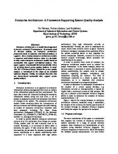
conditions to be modeled and simulated, such as material characteristics and forces to apply in the simulation The SEACAS toolset has many components in each functional category both as a result of the history of its development and the wide variety of approximations appropriate to each actual analysis. We met with experts from Sandia and developed a scenario incorporating a subset of the tools in the SEACAS toolset. This included two problem definition tools FASTQ and GEN3D, an analysis simulator JAS3D and a visualizer BLOT. The general usage scenario is as shown in Figure 2.
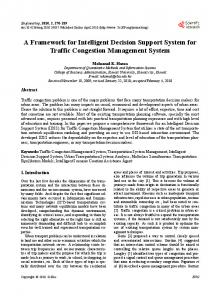
2.3 Current Sandia System and Desired Outcome Sandia provided components from the Sandia National Laboratory Engineering Analysis Code Access System (SEACAS) for the modernization case study. SEACAS is a collection of components that perform the computer based processing tasks needed to support the analysis activity: they provide functions such as defining test conditions (problem description), analysis simulation, and visualization (see Figure 1). These tools share a common data format called EXOProblem Definition • • • •
define geometry discretize model define load locations define material types
Visualization • • • •
model verification analysis tracking define load locations define material types
Exodus II Data Objects • coordinates • connectivity • load locations • results variables Simulation/Analysis • stress analysis • shock physics analysis • structural dynamics analysis Figure 1. SEACAS Tool and Data Relationships DUS II [22]; thus these tools already have a form of data integration. The analysis function is done using a Finite Element (FE) approximation technique[19]. The problem definitions describe how to break up the part being analyzed into elements, how to connect the elements together as well as the
FE Analysis (JAS3D)
2D Mesh Generation (FASTQ) 3D Mesh Generation (GEN3D) 2D Mesh Model 3D Mesh Model
Visualize (BLOT)
3D Mesh Model & Analysis Results
Figure 2. Case-Study Components and EndUser Scenario An analyst uses FASTQ to produce a discretized1 model of the part to be analyzed. This model is stored in a file in the EXODUS shared data format. The visualizing tool BLOT then can be run against the model producing a graphical representation for inspection by the analyst. Based on that inspection the analyst either reruns FASTQ to correct the model or he feeds the model to GEN3D to extrude it into a three dimensional model. Another inspection/correction iteration may occur for the resulting three dimensional model before the model is fed to the analysis tool. One or more analyses may be conducted, with results evaluated via the visualization tool or through inspection of other JAS3D output. Iteration among the various steps is also possible, for example the analysis results might suggest changes to the underlying 2D or 3D mesh. 1. A two- or three-dimensional mesh that models the solid as a set of many smaller linked solids.
In the scenario described above end-users are responsible for launching individual tools (often with personalized scripts), managing tool output (in private directories), and preparing the output of one tool for use as input to another (sometimes with manual application of filters since not all SEACAS tools use the same version of the Exodus data format—both format and tools have evolved over time). In effect, the end-user is the system integrator, continually exposed to all of the low-level details and technology dependencies exhibited by the SEACAS components. TIE-In (the NIST and SEI projects as well) wanted to demonstrate a modernization of SEACAS that would: • present a uniform virtual environment for end-users that would reflect the nature of the analysis activity and not the idiosyncracies of specific SEACAS components; • support wide-area distribution of SEACAS services while maintaining control over the software that provides these services (some of which contain classified algorithms); • provide a measure of security not just against theft of software but also reliability and prevention of malicious or inadvertent denial of service; and, • deliver reasonable, usable and predictable performance to end-users who are otherwise accustomed to using computer services in local area network settings. It seemed to us that distributed object technology, and CORBA in particular, might provide a means of achieving these objectives—or at least the SEACAS modernization would reveal limitations of CORBA in meeting these objectives—either of which would meet our organizational and project objectives.
2.4 Technology Influences Many organizations will have made some technology commitments in advance of a thorough requirements analysis and design trade-off analysis. It is important to understand the consequences of these commitments on both the target system and software development strategies. Our decision to use CORBA as a foundation for the modernization effort represents an important technical constraint: • CORBA is new technology, and although there are numerous commercially-available object request brokers (ORBs), the underlying CORBA specifications are changing. The instability of implementations and specifications is an important design factor. • CORBA is intended to be only a communication infrastructure within a larger distributed object technology—the object management architecture (OMA) [3]. ORB vendors are not required to implement OMA services. Thus, the decision to rely upon a vendor’s implementation of OMA services presents risks, as does
the decision to implement interim services in anticipation of OMA services not yet available. • There are no well-established architectural styles [6] for distributed object technology that have been demonstrated to be effective with the OMA. It is possible to analogize from established architectural styles; however, there may be subtle mismatches between these and the OMA. For example, a repositorystyle integration architecture [8] can in theory be supported by the OMA. However, the OMA lacks support for critical database features, and assumptions concerning object granularity, security, etc., could cause severe performance problems. • The OMA specifications describe services from an object consumer’s perspective, not from the perspective of an object supplier. Thus commercial ORBS exhibit a wide range of non-standard implementation features. Such vendor dependencies represent potential risks to the survivability of a re-engineering solution given the volatility of the OMA specifications and marketplace. Unfortunately, it is not always easy to identify such dependencies, nor to avoid them if identified.
2.5 Systems influences Different kinds of system properties will strongly influence modernization strategies. System properties may either be intrinsic to the system, or they may be extrinsic properties that the system must exhibit. Examples of intrinsic properties include: distributed processing, client-server orientation and multi-processing. Examples of extrinsic properties (or quality attributes [4]) include fault tolerance, multi-level security and performance1. Different systems exhibit different patterns of intrinsic and extrinsic properties; some of these patterns arise with sufficient frequency to warrant classification as a kind of system. We refer to the kind of system that was the subject of the case study as a component-based system. While all (real) systems are composed of components, in our usage the term component-based refers to systems that are comprised of multiple software components that: • are ready “off-the-shelf” whether from a commercial source (COTS) or re-used from another system; • have significant aggregate functionality and complexity, i.e., play the role of subsystems in the final system; • may be self-contained and execute independently; 1. One way to differentiate these classes of properties is to consider intrinsic properties as representing bound design and implementation decisions, while quality attributes are externally-visible system properties that deal with issues other than functionality.
• will be used “as is” rather than modified; and, • are treated as black- (or very opaque-) boxes in that their implementations are independent of each other. Examples of component-based systems can be drawn from many domains, including: computer-aided software engineering (CASE), design engineering (CADE) and manufacturing engineering (CAME); office automation; workflow management; and command and control. The stipulation that multiple components must be involved is important since this intrinsic system property defines a range of problems that must be addressed and dictates the kinds of engineering techniques and technologies needed to address these problems. One key problem introduced by component-based systems can be summed up with the phrase architectural mismatch [5]: components embed assumptions about the architectural and operational context in which they operate, and these assumptions often conflict with the architecture of the target system and with assumptions manifested by other components. The engineering techniques that are needed to address architectural mismatch are centered on the notion of systems integration as a design activity. In contrast to the development of other kinds of systems where system integration is often the tail-end of an implementation effort, in component-based systems determining how to integrate components is often the only latitude designers have. Quality attributes such as usability, availability, and maintainability are influenced by and help shape integration decisions such as: which components need to be integrated to which; how component execution is coordinated; which architectural mismatches must be resolved, and which mechanisms are used to adapt components to remove these mismatches. To understand where such mismatches might arise when integrating two or more components, it is useful to have some idea of what it means to integrate components—and this turns out to be surprisingly elusive. One useful way to think of integration is as a relationship between two integrated entities, where the relationship has four dimensions, or aspects: control, data, process, and presentation [9][10]: • Control integration describes how components make requests of (or invoke) each other’s services. • Data integration describes how components make data available to each other. • Process integration describes what end-user or business process is supported by the integration relationship. • Presentation integration describes how end-users interact with the integration relationship, i.e., how to achieve a uniform model of human interaction.
All four aspects will be reflected to different degrees in each integration relationship. Although these aspects are entirely qualitative and descriptive, and there are no causal connections between these and quality attributes, they provide a useful if limited framework for discussion, and will be referred to in the following discussion.
2.6 Architectural Influences Frameworks vs. Opportunistic Integration We refer to technology infrastructures that present a coherent and common view of integration within a class of systems as integration frameworks. A number of integration frameworks have been developed to support component integration in the CASE domain, each with its own particular emphasis on one or more aspects of integration [15]. For example, PCTE [16] provides a range of integration services that emphasize data integration, while ToolTalk [17] provides services that emphasize control integration. Within the manufacturing domain the SEMATECH CIM1 application framework is both an integration framework and an instance of an architectural style referred to by the object-oriented community as an application framework2; it emphasizes control and process integration. The cost of developing or using application or integration frameworks can be great, and includes both the cost of developing or licensing the framework and the cost of introducing changes in engineering practices. In some situations a more opportunistic approach to integration may be desirable. That is, rather than use a framework that imposes a common approach to all integration problems, each integration problem is viewed as a unique problem. While opportunistic integration may result in extra effort and inconsistent solutions, it is flexible and can address application-specific design problems and can accommodate new integration technologies. Opportunistic integration does not imply hacked, ad hoc solutions; indeed, there are several architectural styles that may be applicable to component-based systems that do not depend upon integration frameworks (e.g., the “communicating objects” style [6]). Functional vs. Structural Architectures A major design issue is whether to adopt an architectural style that emphasizes the functionality of the system and its
1. SEMATECH is an industry consortium; the Computer Integrated Manufacturing (CIM) Application Framework is one product of the consortium. 2. The term “framework” in application framework and integration framework describes different concepts: the former describes a partial application that is completed by the developer or integrator, while the latter describes infrastructure that is independent of application functionality.
components, or a style that emphasizes the structure of a system based on how the components interact rather than on what functions they provide. We refer to the former class of styles as functional styles, and the latter class as structural styles. Functional styles are far and away the predominant approach to component-based systems; this approach defines components in terms of their functionality, e.g., database. The interfaces between components are often expressed as function-specific application programming interfaces (API) or as standard mechanisms (e.g., SQL for databases). Numerous examples of functional architectures can be found in [8]; a good example for the CAME domain is found in [11]. Functional architectures are good for describing what kinds of technologies are needed to implement a desired system functionality, the overall role each technology will play and which technologies are likely to interact. They are weak when it comes to describing non-functional properties of a design (throughput, reliability, etc.), and generally result in an ad hoc integration where each particular inter-component relationship is implemented as component-specific “glue.” Structural styles are of more recent vintage but have been emerging as the study of software architecture has intensified. Rather than defining component interfaces in terms of specific functionality, structural styles define interfaces in terms of the role a component plays in the architecture—often describing a coordination model (i.e., control and data flow). A commonplace illustration of a structural style is UNIX pipes and filters; more sophisticated illustrations include structural models for flight simulators [12], the Simplex architecture for evolvable real-time systems [13], and UNAS for distributed, concurrent systems [14]. Since the structural form of the architecture is often directly related to the architecture’s intrinsic coordination model, a range of quality attributes can be understood from any particular design expressed using the structural form; further, the structure defines a uniform strategy for inter-component integration. However, it may be difficult to determine just what function is being computed by a system from a structural architecture.
3. Modernization Case Study With these technical and non-technical influences in mind, it is possible to describe the architecture and implementation of the prototype, and to describe in some detail how a particular trade-off analysis of the influences and technical approaches described above are reflected in the solution.
3.1 Architectural Issues and Trade-offs Figure 3 depicts a top-level view of the prototype architecture. The three layers reflect the different kinds of integration issues being addressed:
distributed object users
lightweight graphical interface & scripting
presentation and process layer logical object layer physical component layer
Host 1
Host 2...
Host N corba object
native tool users
component relationship invocation
Figure 3. Architectural Overview • The (top-most) presentation and process layer addresses presentation and process integration. Both aspects are addressed in the prototype by Tk/TCL [18]. It is depicted as a separable entity from the lower layers, principally because it can be designed and implemented in a way that is independent of object location or how the objects are implemented, thus providing some support for the desired end-user “virtual environment.” • The (middle) logical object layer addresses control and data integration. Control integration is achieved using a structural rather than functional interface (this is discussed in more detail later); data integration is achieved by object persistence and relationships. It is at this layer that most of the detailed architectural issues related to quality attributes are addressed. • The (bottom-most) physical component layer addresses the management of physical resources (files, operating system processes, etc.) and issues of architectural mismatch between the components and the architectural forms reflected by the logical object model (discussed more fully in Section 3.2). The two kinds of end-users depicted in Figure 3 reflect a non-intrusive modernization strategy. It was important to preserve the existing methods and mechanisms for accessing tool services since (a) we were dealing with a technology that had many unknowns (CORBA), and (b) we were only migrating a portion of the SEACAS system to distrib-
uted object technology. Supporting both classes of users involved additional coding effort, for example to provide complementary tool data management services to those provided in the native environment, so that object-based users did not interfere with native tool users (and visa versa). But the extra effort was deemed less important than supporting a non-intrusive modernization. Figure 4 depicts the logical object layer in more detail. The Application Objects
Framework Objects
Wrappers
Structural Objects
other meshes get_object
relationship object
specification update done? consistent?
mesh object
pull_event push_event
eventqueue object
incremental results native component component adaptor code
Additional Framework Services for Component Adaptation
Figure 4. Structural Architecture (Overview) objects that implement the structural architecture are referred to as structural objects in Figure 4. Two kinds of structural objects are depicted in Figure 4: application objects and framework objects. Application objects implement system functionality and most of the coordination model, while framework objects provide needed integration infrastructure services (which were needed despite our desire to pursue an opportunistic integration approach). Framework objects are discussed in detail in Section 3.2. The coordination model is implemented by application objects that behave as state machines that are either consistent or inconsistent with respect to some specification. Specifications represent human input (e.g., mesh models, analysis instructions), and consistency represents whether component-generated data was derived from the specification. Components are invoked as a result of update operations; they return diagnostic data directly to the invoking object (not shown); they may also return other data, such as incremental results from long-running analysis sessions, via event channels. This structural approach simplified the task of understanding and analyzing how the object model would behave in a
wide-area distributed setting. For example, we were able to tune the coordination model to various kinds of network failure modes (partition, node crashes, etc.), and to express these tunings directly in the structure of the architecture. The structural approach also helped to focus the component adaptation/wrapping to those aspects of the design that were sensitive to coordination issues, for example whether simultaneous invocations of the component were supported, how to address network disconnections. We considered adopting a functional approach, essentially just wrapping the SEACAS components “as is” using a remote procedure call (RPC) metaphor1. We rejected this because the approach would not address data integration requirements: this would have required us to develop additional data management services, or else to parameterize the RPC interfaces to allow data interchange of lengthy data streams—neither of which was desirable. Beyond these problems, an RPC approach would have exposed tool technology to the programming interface; this would make the modernized SEACAS system less adaptive to new components and component upgrades, as the revealed technology dependencies are invariably reflected in end-user systems and interfaces such as we developed.
3.2 Detailed Design Trade-Offs A number of modernization trade-off decisions arose at more detailed levels of the design and implementation of the modernized system. For discussion purposes these have been categorized according to the aspects of integration which they addressed (process, presentation, control and data integration). Process, Presentation Integration in Distributed Systems The detailed design of our prototype was driven largely by the end user process it supports. There were many similarities in steps between the user process activities for two dimensional mesh generation, three dimensional mesh generation and mesh analysis. These similarities led naturally to the model shown in Figure 5, which depicts the major object types found in the logical object model layer of the architecture (Figure 3). The structure of these objects reflects the end-user process: an analyst using the SEACAS tools is primarily concerned with data elements, (e.g. input commands, output diagnostics, and mesh binaries), and relationships among them. These relationships are expressed in the object model as object relationships, and are modified by the value of attributes such as Consistent. Relationships and their modifying attributes capture the 1. Using the earlier concepts, we can describe the RPC approach as opportunistic integration (minimal or no use of framework services) in a functional architecture.
string DisplayName string Commands ViewData raw_data
display viewer (BLOT)
view update
exodus
string Name boolean Consistent boolean Active string Diagnostic
string analysis update (FASTQ)
update (JAS3D) exodus3d analysis
exodus2d
string Specification
update (GEN3D) exodus3d
corba object relationship attribute subclass
string Extrusion
push try_pull
event queue
Figure 5. Object Types and Relationships evolution of a mesh instance through the user process from 2D to 3D and finally to a full analysis. The decision to express end-user processes in the form of a logical object model represents a major design trade-off between the desire to achieve a tight coupling between an object model and end-user processes versus the potential need to evolve end-user processes over time: all data schemas embed process assumptions, and tighter coupling between process and data model implies a less evolvable data model [23]. For this case study we decided that the process of describing and analyzing solid models was sufficiently mature that drastic changes to the process model were not likely. The point to note, however, is that this modernization decision was informed both by quality attributes (evolvability) and domain-specific influences (the stability of end-user processes in this case). In an interactive system issues of performance are closely related to end-user process. Because of the compute-intensive character of analysis simulation, we anticipated that this could be run on a supercomputer, while we expected an analyst to be sitting in front of a workstation (PC or supermicro), and operating in a remote (to the simulation service) location. Thus, another set of trade-off decisions involved where on a network topology objects live, and how much visibility endusers have on object location and on the performance characteristics of the underlying hosts (for example, to estimate the time required to complete an analysis session).
For this design, we opted to make object location and host details as transparent as possible to end users. This involved a trade-off between end-user flexibility and complexity. Our decision to opt for object location transparency was informed by an objective assessment of the state of CORBA and CADE technology and the current state of manufacturing engineering: there simply was no technical or business basis upon which to develop or anticipate the use of advanced service brokering services that might require greater visibility into object and network topologies. This decision also represented a desire to introduce the minimum number of new concepts to the existing system that are necessary to support our modernization objectives. Nevertheless, despite this simplification, details of object location were reflected on the structural model in the way visualization and the event queue objects are defined. Control, Data Integration: Needed Framework Services Since the OMA is not yet a sufficiently mature integration framework, and since the ORB implementation we were using did not implement OMA services beyond the minimal CORBA specification, we were predisposed to try to use the OMA to support opportunistic integration. However, we discovered that even an opportunistic approach to integrating component-based systems requires an extensive range of integration framework services (as this term is defined in Section 3.1). Two categories of integration framework services were needed: one to deal with integration in the logical object model layer, and one to deal with tool adaptation at the physical component layer. At the logical object layer both control and data integration services were required. While both forms of integration are supported OMA services, our ORB implementation did not support them. This necessitated a trade-off among: • the degree to which we wanted our logical object model to mirror the end-user process model; • the amount of code we were willing to write to implement OMA-compliant services; and, • the degree to which we were willing to have the design reflect a non-standard approach by implementing subsets or alternative forms of OMA services. In the final analysis, we opted to introduce non-standard forms of OMA services. We determined that the initial technical objective—providing a virtual environment to the end-user—was important enough to justify integration at the logical object layer, but we knew that this would require use of OMA services such as object persistence and relationships. At the same time, resource constraints on the effort made the implementation of standard OMA services
problematic. Therefore, we implemented the needed OMA services, but only partially and in ways not consistent with the OMA specifications. This resulted in a design that was functional but that does not reveal the capabilities of the OMA; this represents a compromise to NIST and SEI objectives. At the physical component level integration services are required that support what are referred to as “wrappers” in Figure 3. These services include: operating system process and file management; management of process families; detection of component failures and crashes; and system diagnostics. From this list it is obvious that these services are highly dependent upon the host platform and properties of the components being adapted. What is less obvious is that there are additional services needed that are dependent upon the target system’s software architecture. While this is not surprising when one considers that the purpose of tool wrapping is to resolve architectural mismatch, and must therefore address both architecture and component aspects of adaptation, it is not generally realized that architectural design must also accommodate the cost and complexity of developing architecture-specific component adaptation services. To illustrate architecture-specific integration consider, from Figure 4, the connection of component output to an event channel. This clearly requires adaptation services to support an interface from the tool wrapper to an OMA object. However, depending on the nature of the components and host platform, a range of other wrapper-level services may also be necessary to support this connection. For example, in our implementation, sending incremental results to the event channel required the assistance of a “helper process” that monitored component output files for changes in status; new data on these files was filtered and passed to the event channel. The use of helper processes required additional services to support parsing and filtering of tool data, and also services for managing the life cycle of process families (e.g., termination of the component should terminate helper processes).
4. Outlines for a Re-engineering Decision Framework The case study has illuminated several of the goals, approaches, and influences at work in a non-trivial modernization (technology incorporation) effort. As suggested in the introduction, we believe that these aspects form the embryonic basis for a decision framework for this kind of reengineering. Specifically, we see evidence for a framework whose structure is greatly simplified in Figure 6. We will discuss each of the named outputs in turn. Technology Target What technology will be imported into the enterprise and its products as a result of the modernization effort? The first task for deciding this is to explicitly articulate the motivations and goals for the effort. Technical goals often include enhanc-
Goals for the modernization
Available technology areas
Current system class
Target Resulting Integration Migration technology system class strategy strategy Figure 6. A decision framework for modernization ing the qualities or utility of the subject system. These typically include better performance or resource utilization, new or enhanced functionality, or the addition of qualities such as security, availability, or support for multiple users in a distributed environment. The last was an explicit goal of the modernization effort described in the case study and drove us to adopt distributed object technology. Further motivation included adoption of a technology (CORBA) whose use was widespread and growing, in order to be able to provide systems that were compatible with it. Although this effort had a decided research or investigative theme, the desire to support a popular technology often occurs in production organizations as well. A tool vendor adopts a widely-used technology to make his products compatible and hence more marketable. A consumer is motivated by the high level of support and flexibility offered by popular technologies. Market forces often transcend issues of technical superiority. Organizational goals may include the ability to rapidly turn out new versions of the system, or to deploy the system in multiple versions as a product line. Sometimes, as was the case for us, the organization’s goal is to become adept at handling a particular technology. Two themes may be seen. The first theme is that the new technology has been chosen a priori, for market or organizational reasons. The second is that other qualities are being sought, and the choice of technology to achieve those qualities is still unresolved. In between lies the case where a technology area has been chosen (such as distributed object technology), but the precise instantiation of it (such as CORBA) has not. The model in Figure 7 is suggested. But more generally, we see that choice of technology— if articulating the goals fails to identify it directly—is a function of the motivating goals for the effort, as well as properties of available technology areas such as maturity, available, breadth of user community, expense, in-house expertise, suitability of purpose in achieving the goals, and
Migration Strategy Goals articulated
Technology chosen a priori
Technology area chosen, specific choice still open
At least four factors play a role in determining if modernization should be all at once, or staged incrementally. Technology area choice still open Proceed to choose technology area.
Perform market, technical analysis of possible solutions. Choose best one for specific goals. Proceed to choose migration and integration strategies Figure 7. A decision path based on goals. the ability of the current software architecture to accommodate the technology. One such decision-making process is described in [7]. Resulting System Class Our case study illustrated modernizing a component-based system. This is in contrast to organic systems whose parts are built or modified in-house, and also in contrast to tightly confederated systems where the components work together via tightly interactive protocols (such as complex application programmer interfaces). In the latter case, the components are less able to do useful work in isolation. These two classes suggest quite different strategies for integrating the parts, and maintaining the integrity of the integrated whole. Other classes of systems that have equally broad implications for system-building, but which were not explicitly addressed in our case study, were real-time systems. As is the custom, we distinguish between hard-real-time systems (which must meet concrete process deadlines), soft-real-time systems (whose correctness criteria are often phrased in terms of non-unit probabilities or process priorities), and non-realtime systems (which have implicit timing requirements). Likewise, the decision about whether the system will work in a distributed or parallel computing environment has broad ramifications for its migration to new technology. The choice of system class is influenced most heavily by the choice of imported—for example, CORBA strongly supports non-real-time component-based distributed systems— but also a function of the system class before modernization begins. Organizations will find it harder, and hence less likely, to shift the class of system.
The first factor is the difference between the current system and the desired state of the new system. For example, adding hard-real-time constraints to a non-real-time system represents a major migration effort that is much different than upgrades to achieve a new system in the same class. The second factor is whether or not the goals for modernization include any that would be met by intermediate products developed by an incremental update strategy. The third factor is a function of the organization. How much expertise, over and above what is available in the organization, will be required for importing and deploying the chosen technology? The fourth factor is a function of the chosen technology area. A mature technology, with an active user community and plentiful support tools can be fielded with less risk than a new technology with little community experience. Figure 8 shows how goals, system class, organizational factors, and technology suggest a migration strategy. Intermediate products useful in their own right? no
yes
yes
Incremental migration strategy
no
New system class large variation from current system?
yes
Low risk technology for organization?
no
Monolithic migration strategy
no
yes
Mature technology?
Figure 8. Choosing a migration strategy Integration Strategy Integration strategy has to do with how to make the components in a component-based system interact with each other in a correct, usable, and efficient manner. Integration strategy may have a different meaning for a system in another class; this is an area of the framework that we have not explored. However, for component-based systems, the issues (each discussed previously) are as follows. One is the issue of frameworks versus opportunistic integration, which was discussed in Section 2.6. Resolving this choice will be a function of the technology chosen (for example, choosing CORBA as provided by the OMA
framework resolves this choice), the components at hand, and the organization’s expertise. Another, also discussed in Section 2.6, is the issue of functional versus structural architectures. A third is concerns aspects of integration (control, data, process, or presentation), discussed in Section 2.5. The last is strongly influenced by the first; a framework-based approach will emphasize a particular range of integration aspects.
[5]
[6]
5. Conclusions and Potential Next Steps We have described a case study in reengineering via technology modernization. The case study was a high-fidelity exercise in that its motivations were authentically motivated by real-world concerns such as supporting a distributed client base and making separately-developed tools work seamlessly to perform industrially useful work. In addition to providing specific lessons and trade-offs about the introduction of distributed object technology in a component-based system, we have shown how the modernization exercise was influenced by several factors such as the goals nature of the participating organizations, the class of system being updated, and the choice of technology. We believe that a decision framework for modernization exists, and that our case study represents a single path through that framework. The case study has illuminated the path we travelled, suggested nearby paths, and hinted at the existence of the framework as a whole. We have presented the work in terms of the decision framework, because we believe that now is an opportune time to challenge the reengineering community to work collaboratively towards building and instantiating as much of this framework as possible. Real-world reengineering case studies will become more common and available as the field matures. We hope and expect that an industrially robust decision framework for reengineering, based on sound experience, may soon be within our collective grasp.
[7]
[8] [9] [10]
[11]
[12]
[13]
[14]
[15]
6. Acknowledgments The SEI is sponsored by the U.S. Department of Defense. Neil Christopher of NIST Manufacturing Engineering Laboratory deserves a large measure of credit for making this work possible and for setting out the broad objectives for the work.
7. References [1] SEI Reengineering Project Description, http://www.sei.cmu.edu/~reengineering [2] The Common Object Request Broker: Architecture and Specification, Revision 1.1, OMG TC Document 91.12.1, Object Management Group, 492 Old Connecticut Path, Framingham, MA, 01701 [3] Object Management Architecture Guide, Revision 2.0, Second Edition, OMG TC Document 92.11.1, Object Management Group, 492 Old Connecticut Path, Framingham, MA, 01701. [4] Abowd, G., Bass, L., Kazman, R., Webb, M., “SAAM: A Method for Analyzing the Properties of Software
[16] [17] [18] [19]
[20]
[21] [22] [23]
Architecture,” in Proceedings of the 16th International Conference on Software Engineering, Sorrento Italy, May 1994, pp. 81-90 Garlan, D., Allen, R., Ockerbloom, J., “Architecture Mismatch: Why Reuse is so Hard”, IEEE Software V12, #6, pp17-26, November 1995. Garlan and Shaw, “An Introduction to Software Architecture,” in Advances in Software Engineering and Knowledge Engineering, vol. I, World Scientific Publishing Company,1993 Brown, A., Wallnau, K., “A framework for systematic evaluation of software technologies” to appear in the special issue of IEEE Software on assessment of software tools, September 1996. Principles of CASE Tool Integration, Alan Brown, et. al., Oxford University Press, 1994, ISBN 0-19-509478-6. Thomas, I., Nejmeh, B., “Definitions of tool integration for environments,” IEEE Software 9(3), pp. 29-35, March 1992. Wasserman, A., “Tool integration in software engineering environments,” in F. Long, ed., Software Engineering Environments, Lecture Notes in Computer Science 467, pp. 138-150, Springer-Verlag, Berlin, Germany, 1990. Brown, A., Judd, R., Riddick, F., “Architectural issues in the design and implementation of an integrated toolkit for manufacturing engineering” submitted to the International Journal of Computer Integrated Manufacturing. Structural Modeling: An Application Framework and Development Process for Flight Simulators, Gregory Abowd, Bass, L., Howard, L., Northrup, L., SEI Technical Report, CMU/SEI-93-TR-14, August, 1993, Software Engineering Institute, Carnegie-Mellon University, Pittsburgh, PA. SA Software Architecture for Dependable and Evolvable Industrial Computing Systems, Sha, L., Rajkumar, R., Gagliardi, M., SEI Technical Report, CMU/SEI-95-TR-005, July 1995, Software Engineering Institute, Carnegie-Mellon University, Pittsburgh, PA. Royce, Walker, Royce, Winston, “Software architecture: integrating process and technology” TRW Space and Defense, Quest, Summer 1991. Also see http://www.stars.reston.unisysgsg.com/arch-006.html. NIST, “Next Generation Computing Resources: Reference Model for Project Support Environments (Version 2.0)”, NIST Special Publication 500-213, November 1993 Wakeman, L. and Jowett, J., “PCTE: The Standards for Open Repositories”, Prentice-Hall, 1993. Frankel, R., “Introduction to the ToolTalk Service”, Sun Microsystems Inc., Mountain View, CA., 1991. Ousterhout, J., “Tcl and the Tk Toolkit”, Addison Wesley. Finite Element Methods in Stress Analysis, Ivar Holand and Kolbein Bell, eds., Tapir: Technical University of Norway, Trondheim, Norway, 1969. Barkmeyer, E., Hopp, Pratt, Rinaudot, SIMA Background Study, Technical Report NISTIR 5662, National Institute of Standards and Technology, 1995. Barkmeyer, E., SIIMA Reference Architecture Part I: Activity Models, NIST Technical Report (in publication). Schoof, L., Yarberry, V., Exodus II: A Finite Element Data Model, Sandia Report SAND92-2137-UC-705, Sept. 1994. Bremeau, C., Thomas, I., “A Schema Design Method for PCTE”, in proceedings of the PCTE 1993 Conference, ISBN 0-95-10631-2-X.