Electromagnetic bearings have a number of important advan- ... tromagnet pulling into the direction of the deviation. ... the current controlled system is designed in continuous time ... Figure 1: The shaft with its radial magnetic bearings. .... i=1. (ix,p(tk + Ïi),ix,n(tk + Ïi)). (11). In the sequel, we refer to this method as mean-value-.
Discrete-time flatness-based control of an electromagnetically levitated rotating shaft J. von L¨owis, J. Rudolph, F. Woittennek Institut f¨ur Regelungs- und Steuerungstheorie Technische Universit¨at Dresden, Mommsenstr. 13 D-01062 Dresden, Germany {loewis,rudolph,woittenn}@erss11.et.tu-dresden.de Keywords: Differential flatness, discrete-time, trajectory tracking, time-varying observer.
Abstract Differential flatness of the mathematical model of an electromagnetically levitated shaft is exploited for trajectory tracking. Emphasis is put on the flatness-based implementation of a discrete-time control law. The control law is completed by a time-varying observer. Both the control by coil currents and voltages is illustrated in simulation.
1
Introduction
Electromagnetic bearings have a number of important advantages over conventional bearings. For example, they do not require a lubricant and have lower friction at high speeds. Furthermore, magnetic bearings can be used to suppress shaft vibration and position the rotor to follow some prescribed trajectory. These last two features cannot be readily achieved with conventional bearings. Magnetic bearings are unstable systems, as can be seen by the following reasoning. Consider a ferromagnetic body placed between two electromagnets pulling into opposite directions. At the equilibrium position the resultant force, i. e., the sum of the electromagnetic forces and the gravitational force, is zero. The attracting electromagnetic force decreases with increasing distance of the body from the magnet, and it increases with decreasing distance. Therefore, if the body is moved away from the equilibrium it is attracted by the electromagnet pulling into the direction of the deviation. As a consequence, feedback is required for the operation of magnetic bearings. The dynamics of the electromagnetically levitated rotating shaft is nonlinear both due to the rigid body dynamics and due to the relations between coil currents and forces. However, the model is differentially flat [1, 2]. This property allows a relatively simple design of continuous-time controllers most appropriate for the trajectory tracking. This approach has been discussed in some detail in [3]. For the implementation it is important that discrete-time control
laws can be directly derived from the continuous-time design without discretizing the model (this approach is related to [4]). This discrete-time design is discussed in the present paper. We describe control laws designed for a rotating spindle built at the German company AXOMAT in Berggießh¨ubel (Saxony). In view of their general applicability, our results have a certain theoretical importance. We first discuss the control through the coil currents. This is the usual mode of operation. The extension to the control through the coil voltages is also included. In both cases, time-varying observers can be used to estimate unmeasured velocities as well as disturbances. We propose a complex variable notation for a simplified design of these observers. The paper is structured as follows. The mathematical model is given in Section 2 and the flatness-based controller for the current controlled system is designed in continuous time in Section 3. The corresponding discrete-time controller is discussed in Section 4. Section 5 is dedicated to observer design, Section 6 treats the voltage controlled system, and some conclusions are drawn in Section 7.
2
The mathematical model
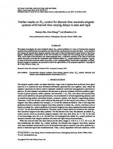
The device considered is equipped with five pairs of electromagnets which support a rotating shaft in its radial and the axial directions — see Fig. 1. A model of the shaft is ¨ = Fx,p − Fx,n +m gx mX | {z }
(1a)
Fx
m Y¨ = Fv,y,p − Fv,y,n + Fh,y,p − Fh,y,n +m gy {z } | {z } | Fv,y
Fh,y
m Z¨ = Fv,z,p − Fv,z,n + Fh,z,p − Fh,z,n +m gz {z } | {z } | Fv,z
(1b) (1c)
Fh,z
Θ2 ψ¨ = −(lf,v − X)Fv,z + (lf,h + X)Fh,z − Θ1 φ˙ θ˙ (1d) ¨ ˙ Θ2 θ = (lf,v − X)Fv,y − (lf,h + X)Fh,y + Θ1 φ ψ˙ (1e) ¨ Θ 1 φ = Dφ . (1f)
Ym,h , Zm,v , and Zm,h from center position is measured in y- and z-direction: Ym,v = Y + lm,v θ, Zm,v = Z − lm,v ψ,
Ym,h = Y − lm,h θ
Zm,h = Z + lm,h ψ.
(4)
These equations can be solved for the generalized coordinates Y , Z, θ, and ψ. A fifth sensor measures the axial position X. Finally, the angular velocity ω = φ˙ is measured, too.
3
Flatness-based control
Considering the equations of motion (1) auxiliary (acceleration) variables can be introduced as ax , ay , az , αψ , αθ , αφ : m a x = Fx + m g x m ay = Fv,y + Fh,y + m gy m az = Fv,z + Fh,z + m gz
Figure 1: The shaft with its radial magnetic bearings. Here X, Y , and Z are the coordinates of the center of mass G of the shaft in a frame (with axes x, y, and z) fixed in space, at a point being considered as the “center” of the device. The angles φ, ψ, and θ describe the angular position of the axes of a body-fixed frame. The coil forces are denoted by F• , the motor torque as Dφ . (Here and in the sequel bullets are to be replaced by appropriate indices.) The shaft has mass m and moments of inertia Θ1 and Θ2 , lf,v and lf,h are the distances between the symmetry planes of the bearings (where the forces F• are produced) and the point G. The forces are related with the currents by F • = k•
i•2 (σ• − s• )2
(2)
where the displacements from the magnetic centers are given by sv,y,• = ±(Y + lf,v θ) sv,z,• = ±(Z − lf,v ψ) sx,p = −sx,n = X.
sh,y,• = ±(Y − lf,h θ) sh,z,• = ±(Z + lf,h ψ)
Θ2 αψ = −(lf,v − X)Fv,z + (lf,h + X)Fh,z − Θ1 φ˙ θ˙ Θ2 αθ = (lf,v − X)Fv,y − (lf,h + X)Fh,y + Θ1 φ˙ ψ˙ Θ1 α φ = D φ .
(5) With this ¨ = ax , Y¨ = ay , Z¨ = az , ψ¨ = αψ , θ¨ = αθ , φ¨ = αφ , X and a stabilizing controller can easily be designed for each of the decoupled subsystems. For example for the position X: ¨ ref − k1 e˙ x − k0 ex , ax = X
(6)
where Xref is a twice differentiable reference trajectory and controller gains k0 , k1 > 0. The tracking error ex := X − Xref now satisfies: e¨x + k1 e˙ x + k0 ex = 0.
(7)
(3)
The system has eleven inputs: the currents through the coils of the electromagnets and the torque produced by the motor (not shown in Fig. 1). However, only one force is created by each pair of coils, and considering the resulting force as the input reduces the number of controls to six: Fx , Fv,y , Fh,y , Fv,z , Fh,z , Dφ . In the controller the ten coil currents can be computed from the five forces. This can be done in such a way that at each time instant only the current creating a force in the direction of the resulting force is set different from zero [3]. In contrast to this, “bias currents” are required in classical linear approaches. These lead to large Joule effect losses, which can be avoided with the flatnessbased nonlinear control. In two measurement planes (perpendicular to the xdirection) at x = lm,v and x = −lm,h the deviation Ym,v ,
Using (6), we compute the auxiliary accelerations ax , . . . , α φ . From these accelerations the forces and the torque Dφ are obtained by solving the inhomogeneous linear system (5). Finally, for a positive force F• the control current i•,p in the corresponding winding is obtained from s F• i•,p = (σ•,p − s•,p ), (8) k•,p while the current i•,n (generating a negative force) is kept zero. p (For negative force F• the currents i•,p = 0 and i•,n = −F• /k•,n (σ•,n − s•,n ) are used.) This approach avoids bias currents required in classical linear approaches: at any instant there is a current in only one coil of each pair [3]. The above design is based on the differential flatness of the model. The coordinates X, Y, Z, φ, θ, ψ form a flat output of the mechanical subsystem [1].
The trajectory planning is simplified by the flatness property. For example, if we want to transfer the center of mass of the shaft within time t∗ from the center position onto an elliptic trajectory we choose
n
Yref (t) = ry (t) cos Ωt Zref (t) = rz (t) sin Ωt Xref (t) = ψref (t) = θref (t) = 0 φref = ω0 t + φ0
k k (Ix,p , Ix,n )
(9)
(ωref = ω0 = const.)
for the components of the flat output (X, Y, Z, φ, ψ, θ) and rz (t) = rz∗ p(t)
ry (t) = ry∗ p(t),
p(t) = 10
4
t t∗
3
− 15
t t∗
4
+6
t t∗
5
.
Since the procedure described in this section can be used to discretize control laws for arbitrary flat systems with linear error dynamics, we start with a general description before detailing it for the axial controller. The radial controllers are designed similarly. We use U k to denote constant inputs applied over the sampling period [tk , tk+1 ). The corresponding continuous-time input will be denoted u(t). Perhaps the simplest way to implement a continuous-time control law on a microprocessor is to compute u(tk ) from measurements and estimates, and to apply this value during the sampling interval [tk , tk+1 ), i. e., choose U k = u(tk ). However, in fast processes — like the spindle considered here — depending on the sampling time Ta , this might not achieve the desired performance. We refer to this method as quasi-continuous control. The flatness-based control approach allows us to propose a different method of discretization. At tk−1 + τ1 (τ1 < Ta , tk = tk−1 + Ta ) both the measurements and the controls U k−1 applied on [tk−1 , tk ) are known. An observer provides an estimate of the system state at time tk . It uses measurements at tk−1 and the controls U k−1 . Flatness is exploited in the computation of the control to be applied on [tk , tk+1 ) through the use of the linear error dynamics assigned to the system by a continuous-time controller. To this end, one aims at computing a “good” approximation U k of the control u(tk + τ ), τ ∈ [0, Ta ). Following [4], the mean value can be used Z Ta 1 Uk = u(tk + τ )dτ, Ta 0 which can be approximated by n
1X u(tk + τi ). n i=1
with 0 ≤ τ1 < · · · < τn ≤ Ta .
(11)
In the sequel, we refer to this method as mean-valuediscretization. The tracking error and its time derivative are given by the difference of the observer state and the reference trajectory
The evolution of the tracking error in case of continuous control is determined by the error dynamics (7) ex (tk + τ ) 0 1 ex (tk ) = exp τ . (12) e˙ x (tk + τ ) −k0 −k1 e˙ x (tk )
Discrete-time control
Uk ≈
1X (ix,p (tk + τi ), ix,n (tk + τi )). := n i=1
ˆ k ) − Xref (tk ), X(t ˆ˙ k ) − X˙ ref (tk )). (e(tk ), e(t ˙ k )) = (X(t
with
Regarding the controller for the axial position X, ix,p and ix,n are the inputs. We now detail, how ix,p (tk + τi ) and ix,n (tk +τi ) corresponding to u(tk +τi ) in (10) are computed in order to get the constant approximations
(10)
When implementing the control law in real-time on a digital computer, one will use ordinary exponentials, sines etc. to express the solution of (7). The matrix exponential in (12) is used only for notational convenience. With (12) and (6) ax (tk + τ ) can be predicted and with ex (tk + τ ) and the reference Xref (tk + τ ) we determine the position1 as X(tk + τ ) = ex (tk + τ ) + Xref (tk + τ ), which is used in (8) to compute the input currents. For example, assuming ax (tk + τ ) > 0 we get s ax (tk + τ ) m (σx − X(tk + τ )) ix,p (tk + τ ) = kx ix,n (tk + τ ) = 0. Note, that since the sign of ax (tk + τi ) is not necessarily the same for all τi ∈ [0, Ta ), the mean value of both input currents may be nonzero even though for each τi either ix,p (tk + τi ) or ix,n (tk + τi ) equals zero. This can be seen on the simulation results shown in Fig. 2 where transitions in the y-direction from −100µm to 100µm, and vice versa, are performed over 5ms = 5Ta . During the first 40 ms the controller is run with mean-valuediscretization. The interval [0, Ta ) is divided into 10 subintervals, i. e., n = 11 in (10). For t ∈ [40ms, 100ms] the controller is run with quasi-continuous discretization, i. e., the inputs are determined according to (6) and (8) with the system state and the reference evaluated at tk . Obviously, the tracking performance is much better when the controller with mean-value-discretization is used, while the currents are smaller. Notice the slight delay between Yref and Y at the beginning of the transitions with the quasicontinuous controller. This delay of approximately Ta does 1 The velocity X(t ˙ k + τ ) can be computed similarly, but for this particular system only X(tk + τ ) is needed to determine the inputs.
150 Y
100
ref
( Z ref,Y ref ) ( Z ,Y )
Y
m,v m,v
80 100
60
40
Y ref, Ym,v in µm
Y ref , Y in µm
50
0
20
0
−20
−50
−40
−60
−100
−80 −150
0
0.01
0.02
0.03
0.04
0.05
0.06
0.07
0.08
0.09
0.1
t in sec
−100
−100
−50
0
Z ref, Zm,v in µm
50
100
6 iv,y,p iv,y,n
100 ( Z ref,Y ref ) ( Z ,Y ) m,v m,v
80 5
60
40
Y ref, Ym,v in µm
iv,y,p , iv,y,n in A
4
3
2
20
0
−20
−40 1
−60
−80 0
0
0.01
0.02
0.03
0.04
0.05
0.06
0.07
0.08
0.09
0.1
t in sec
−100
−100
−50
0
Z ref, Zm,v in µm
50
100
2.5
Figure 2: Vertical position Y and reference Yref for transitions within five sampling periods (Ta = 1ms) and corresponding currents in one bearing. Before t = 40 ms with mean-value-discretization, after t = 40 ms with quasicontinuous discretization.
iv,y,p iv,y,n
2
not appear with mean-value-discretization. This is not surprising since the discretization takes into account the reference trajectory on the sampling interval for which the input is computed. The results of another simulation experiment are shown in Fig. 3. The center of mass of the rotating shaft is transferred onto an elliptic path described by (9) where ω0 = Ω = 500 rad/s, i. e., the elliptic trajectory is synchronized with the angle φ of rotation about the x-axis. The transfer is performed within t∗ = 40 ms, once with mean-valuediscretization and once with quasi-continuous discretization. Notice a rather large error with the quasi-continuous approach. In all simulations, a dicrete-time observer as described in Section 5.3 is used.
iv,y,p , iv,y,n in A
1.5
1
0.5
0
0
0.01
0.02
0.03
0.04
0.05
0.06
0.07
0.08
0.09
0.1
t in sec
Figure 3: Transition of the center of mass onto an elliptic trajectory according to (9), with t∗ = 40 ms, ry∗ = 50 µm, and rz∗ = 100 µm. Top figure: position of the shaft in the vmeasurement plane (mean-value-discretization); middle figure: same as top, but with quasi-continuous discretization; bottom figure: currents in the coils generating Fv,y,p and Fv,y,n in case of mean-value-discretization.
5
Observer design
5.1 Complex variable notation Introducing complex variables χ := ψ + jθ
and
p := Y + jZ
(13)
allows us to write the system equations as well as the equations of the controller and the observers in a compact form. The acceleration of the center of mass (due to bearing forces and gravity) in radial directions then reads ap := ay + j az
(14)
with ay and az as in (5). The angular acceleration due to bearing forces can be written as aχ := aψ + j aθ
(15)
with 1 (−(lf,v − X)Fv,z + (lf,h + X)Fh,z ) Θ2 1 ((lf,v − X)Fv,y − (lf,h + X)Fh,y ) . aθ = Θ2
aψ =
(16)
The key point with the above definitions of ap and aχ is that they are functions of the measured generalized coordinates and the input currents. This is essential for the observer design since it allows to cancel these terms in the observer error dynamics. With ap , aχ , p, and χ the system equations read ¨ = ap p
(17)
Θ1 χ ¨ = jω(t) χ˙ + aχ . Θ2
(18)
Equation (18) is a linear differential equation with a timevarying coefficient, while (17) is time invariant. The equation for the x-direction is even simpler than (17) (since ax and X are not complex) and it is omitted. 5.2
Here, the vectors xp , xχ , and b are defined as p χ 0 xp = p˙ , xχ = χ˙ , b = 1 , βp βχ 0 and the matrices Ap and Aχ are 0 1 0 0 1 0 Ap = 0 0 1 , Aχ = 0 ϕ 1 . 0 0 0 0 0 0
2 For
x˙ p = Ap xp + b ap
(19)
x˙ χ = Aχ xχ + b aχ .
(20)
an approach to the estimation of harmonic perturbations due to imbalance see [6].
(22)
Θ1 Moreover, ϕ(t) := jω(t) Θ is a known function of time, 2 ω(t) being measured. The observer is composed of a simulation of the model and a correction by error injection ˆ˙ = Ap x ˆ + b a + lp (p − p x ˆ) (23) p
p
p
ˆ˙ χ = Aχ x ˆ χ + b aχ + lχ (χ − χ x ˆ ).
(24)
Using (4), the (complex) position p and the angle χ can be computed from measurements. Therefore, p and χ are considered as measured variables for the purpose of observer design. The interesting system is (24), because it is time-varying. The observer error dynamics are obtained as the difference between (24) and (20): 1 0 −lχ,1 ˜ χ, ˜˙ χ = Aχ x ˜ χ − lχ χ x ˜ = −lχ,2 ϕ(t) 1 x (25) −lχ,3 0 0 | {z } =:Acl χ
ˆ χ. ˜ χ := xχ − x with the observer error x When ω varies slowly, it is legitimate to assume Aχ to be constant, depending on the “parameter” ω. Then it makes sense to compute the observer gains lχ,1 , lχ,2 , lχ,3 (depending on ω) such that the characteristic polynomial of Acl χ is independent of ω (see [3]). Extending this approach we aim at a time-invariant observer error dynamics. For the reader’s convenience we rewrite (25) in terms of ˜ ): (x1 , x2 , x3 ) := (˜ χ, χ ˜˙ , β χ x˙ 1 = −lχ,1 x1 + x2 x˙ 2 = −lχ,2 x1 + ϕ x2 + x3
(26)
x˙ 3 = −lχ,3 x1 .
Estimating velocities and constant accelerations
Due to uncertainties on the model parameters steady state position errors are to be expected. These uncertainties have the same effect as constant forces and torques acting on the rigid body. To account for these perturbations the model can be extended by differential equations for constant accelerations2 β p and β χ . With this extension equations (17) and (18) can be written in state space form
(21)
By the change of coordinates z1 := x1 ,
z2 := x2 − ϕ x1 ,
z3 := x3
equations (26) become z˙1 = −lχ,1 x1 + x2 = (−lχ,1 + ϕ) z1 + z2 z˙2 = x˙ 2 − ϕ˙ z1 − ϕ z˙1
= −lχ,2 z1 + ϕ x2 + z3 − ϕ˙ z1 − ϕ(−lχ,1 z1 + x2 ) = (−lχ,2 − ϕ˙ + ϕ lχ,1 ) z1 + z3
z˙3 = −lχ,3 z1 .
˜ ) = (z1 , z2 , z3 ), we obtain the Substituting back, (˜ χ, ˜ξ, β χ error equations ˙ χ ˜ ˜ χ −lχ,1 + ϕ 1 0 ˜ξ˙ ˜ξ ˙ −l − ϕ + l ϕ 0 1 = , (27) χ,2 χ,1 ˜ ˙ β ˜ −l 0 0 χ,3 βχ χ which can be made time-invariant with the characteristic polynomial3 c0 + c1 λ + c2 λ2 + λ3 by choosing the time-varying gains
6
Voltage controlled system
Sometimes it is useful to control the system through the coil voltages instead of the currents. Then, the model is extended by the equations ˙ • = V• − R• i• , Ψ
where R• are the resistances of the coils and V• are the coil voltages. The relation between the flux linkage Ψ• and the coil current i• is given by Ψ• =
lχ,1 (t) = c0 − ϕ
lχ,2 (t) = c1 − ϕ˙ + ϕ (c0 − ϕ)
(28)
(29)
ˆ˙ = χ β ˜ c2 . χ
The angular velocity to be estimated follows immediately from the definition of ξ := χ˙ − ϕ χ as χ ˆ˙ = ˆξ + ϕ χ ˆ. 5.3 Discrete-time observer For the implementation on a digital computer the observer has to be discretized. We restrict ourselves to the subsystem (24) for the angular coordinates χ. For constant or slowly varying ω the discretization of the linear time-invariant system (24) is rather simple in case of constant inputs. The only obstacle is to find a “good” constant approximation for aχ . (For constant input currents the acceleration aχ is usually not constant over the sampling period since the position X, p, χ is changing and the generalized forces depend on currents and position.) In each sampling period, the currents I•k were computed as to achieve a prescribed error dynamics (considering as good as possible the non-constant position). The currents correspond to the average accelerations n
1X a (tk + τi ), n i=1 χ
(30)
computed in a similar fashion as I•k in (11). It seems reasonable to use ν kχ as input for the discrete-time observer ˆ k+1 ˆ kχ + bd ν kχ + lχ,d (χk − χ ˆk ), x = exp(Aχ Ta ) x χ RT with bd = 0 a exp (Aχ (Ta − τ )) b dτ and the observer T gains lχ,d = lχ,d,1 lχ,d,2 lχ,d,3 such that the characteristic polynomial of exp(Aχ Ta ) − lχ,d 1 0 0 has its roots inside the unit circle of the complex plane. 3 Since
(32)
˙ • = V• − R• Ψ• σ• − s• . Ψ 2 k•
The observer equations are given here for completeness:
ν kχ =
2 k• i• . σ• − s•
Thus, equation (31) can be written as
lχ,3 (t) = c2 .
ˆ˙ = χ ˜ (c0 − ϕ) − ϕχ ˆ + ˆξ χ ˆξ˙ = χ ˆ +a ˜ (c1 − ϕ˙ + ϕ (c0 − ϕ)) − ϕ˙ χ ˆ+β χ χ
(31)
the system is complex, the coefficients c0 , c1 , c2 need not be real. Hence, the eigenvalues of (27) need not be complex conjugates.
(33)
The air gap lengths s• depend on the position of the shaft according to (3). The controller may be designed using the idea that current tracking essentially means force tracking (which is what we need to stabilize the motion of the mechanical subsystem). In Section 4 we computed constant currents as “good” approximations of the currents required by a continuous-time controller. In a similar fashion, the controller now generates voltages (constant over a sampling period) which cause currents approximating those of the continuous-time controller. This will be discussed now. From the coil currents i• (tk−1 ) (assumed to be measured) we can compute the flux linkages Ψ• (tk−1 ) using (32). With the voltages V•k−1 (which are known since they are the inputs currently applied) we can integrate (33) on [tk−1 , tk ] to ˆ • (tk ) of the flux linkages (or equivalently obtain estimates Ψ the currents) at time tk . Equation (33) is time-varying, because the air-gap lengths s• depend on the positions. Since generalized positions are measured and generalized velocities are estimated, good estimates of s• (t) can be obtained on [tk−1 , tk ]. Alternatively, assuming the air gaps vary only slightly within a sampling period, one could simply choose s• (tk−1 ). In order to compute the voltages V•k to be applied over the next sampling period, the currents i• (tk+1 ) are determined using the error dynamics — similar to Section 4. In contrast to Section 4, now we compute the currents required at the end of the next sampling period, rather than average currents. The voltages are then computed such as to reach those required currents. For constant V•k the solution of (33) is Ψ• (tk+1 ) = e−
R Ta 0
R• (σ• −s• ) dτ 2 k•
Ψ• (tk ) + V•k Ta .
(34)
The desired currents i• (tk+1 ) are computed as in Section 4, equations (32) then yield the flux linkages Ψ• (tk+1 ). Using ˆ • (tk ) we can solve (34) for Ψ• (tk+1 ) and the estimates Ψ V•k
=
Ψ• (tk+1 ) − e−
R Ta 0
R• (σ• −s• ) dτ 2 k•
Ta
ˆ • (tk ) Ψ
.
(35)
120 X
100
80
60
40
20
0
0
0.005
0.01
0.015
t in sec 7 ix,p ix,n 6
5
ix,p, ix,n in A
7 Conclusion The differential flatness of the mathematical model of an electromagnetically levitated shaft has been exploited to design discrete-time control laws for trajectory tracking. The proposed discrete-time controllers compute constant inputs as to achieve good approximations of corresponding continuous-time controllers with linear tracking error dynamics. By this approach discrete-time control with rather slow sampling can be designed for the differentially flat continuous-time system without discretizing the mathematical model.
ref
X
X ref, X in µm
The currents (resp. flux linkages, resp. forces) obtained with these voltages, V•k , are approximately the same as would result from the continuous-time feedback at time tk+1 , i. e., at the end of the next sampling period. Fig. 4 shows simulation results obtained with the proposed control scheme. A transition in x-direction from center position to X = 100 µm within 6 sampling periods (3 ms) is performed. The initial positions, velocities, and flux linkages are all zero. To avoid singularities in the voltage controlled system (see [3]), which are related to the fact that the righthand-side of (8) is not differentiable at F• = 0, the righthand-side of (8) is replaced by a differentiable term causing non-zero bias currents at small forces (see [3, 5] for a detailed discussion of this issue). For large forces again only the coil current corresponding to the direction of the force is non-zero. As a consequence, now in order to retain the shaft in the center position non-zero currents are necesseary. This can be seen in Fig. 4, where the first voltage peak is needed to reach the bias currents. The transition to 100 µm is performed on [4 ms, 7 ms].
4
3
2
1
0
0
0.005
0.01
0.015
t in sec 300 Vx,p Vx,n
Acknowledgments
References [1] M. Fliess, J. L´evine, Ph. Martin, and P. Rouchon. Flatness and defect of non-linear systems: introductory theory and examples. Int. J. Control, 61(6):1327–1361, 1995. [2] M. Fliess, J. L´evine, Ph. Martin, and P. Rouchon. A Lie-B¨acklund approach to equivalence and flatness of nonlinear systems. IEEE Trans. on Automatic Control, AC-44(5):922–937, 1999. [3] J. L´evine, J. Lottin, and J.-Ch. Ponsart. A nonlinear approach to the control of magnetic bearings. IEEE Trans. on Control Systems Technology, 4(5):524–544, 1996.
100
Vx,p, Vx,n in Volt
This work is part of a research project with AXOMAT G.m.b.H., Berggießh¨ubel, Germany, with financial support by the European Union (EFRE) and the Free State of Saxony (P-No. 5051).
200
0
−100
−200
−300
0
0.005
0.01
0.015
t in sec
Figure 4: Voltage controlled system: Position X and reference Xref for a transition within 3 ms (top figure). Currents ix,p and ix,n in the positve and negative direction coils (middle figure). Voltages Vx,p and Vx,n across the coils (bottom figure). Sampling period Ta = 0.5 ms, voltages computed according to (35).
[4] Ph. Martin and P. Rouchon. Flatness and sampling control of induction motors. In Proceedings of the 13th IFAC triennial World Congress, San Francisco, California, 1996. [5] J.-Ch. Ponsart. Asservissements num´eriques de paliers magn´etiques. Application aux pompes a` vide. Th`ese de Doctorat, Universit´e de Savoie, Annecy, France, 1996. [6] J. Rudolph, F. Woittennek, and J. von L¨owis. Zur Regelung einer elektromagnetisch gelagerten Spindel. at—Automatisierungstechnik, 48(3):132–139, 2000.