Response of LTI systems to arbitrary inputs: the convolution sum . ... terminology,
classes of signals and systems, linearity, time-invariance. impulse response, ...
Chapter 2
Discrete-time signals and systems Contents Overview . . . . . . . . . . . . . . . . . . . . . . . . . . . . . Discrete-time signals . . . . . . . . . . . . . . . . . . . . . . . Some elementary discrete-time signals . . . . . . . . . . . . . . Signal notation . . . . . . . . . . . . . . . . . . . . . . . . . . . Classification of discrete-time signals . . . . . . . . . . . . . . . Symmetry . . . . . . . . . . . . . . . . . . . . . . . . . . . . . Simple manipulations of discrete-time signals . . . . . . . . . . . Correlation of discrete-time signals . . . . . . . . . . . . . . . . Cross-correlation sequences . . . . . . . . . . . . . . . . . . . . Properties of cross correlation . . . . . . . . . . . . . . . . . . . Discrete-time systems . . . . . . . . . . . . . . . . . . . . . . . Input-output description of systems . . . . . . . . . . . . . . . . Block diagram representation of discrete-time systems . . . . . . Classification of discrete-time systems . . . . . . . . . . . . . . Time properties . . . . . . . . . . . . . . . . . . . . . . . . . . “Amplitude” properties . . . . . . . . . . . . . . . . . . . . . . Interconnection of discrete-time systems . . . . . . . . . . . . . Analysis of discrete-time linear time-invariant systems . . . . . . Techniques for the analysis of linear systems . . . . . . . . . . . Response of LTI systems to arbitrary inputs: the convolution sum Properties of convolution and the interconnection of LTI systems . Properties of LTI systems in terms of the impulse response . . . . Stability of LTI systems . . . . . . . . . . . . . . . . . . . . . . Discrete-time systems described by difference equations . . . . . Recursive and nonrecursive discrete-time systems . . . . . . . . LTI systems via constant-coefficient difference equations . . . . . Solution of linear constant-coefficient difference equations . . . . Impulse response of a LTI recursive system . . . . . . . . . . . . Summary of difference equations . . . . . . . . . . . . . . . . . Implementation of discrete-time systems . . . . . . . . . . . . . Structures for realization of LTI systems . . . . . . . . . . . . . Recursive and nonrecursive realization of FIR systems . . . . . . Summary . . . . . . . . . . . . . . . . . . . . . . . . . . . . .
2.1
. . . . . . . . . . . . . . . . . . . . . . . . . . . . . . . . .
. . . . . . . . . . . . . . . . . . . . . . . . . . . . . . . . .
. . . . . . . . . . . . . . . . . . . . . . . . . . . . . . . . .
. . . . . . . . . . . . . . . . . . . . . . . . . . . . . . . . .
. . . . . . . . . . . . . . . . . . . . . . . . . . . . . . . . .
. . . . . . . . . . . . . . . . . . . . . . . . . . . . . . . . .
. . . . . . . . . . . . . . . . . . . . . . . . . . . . . . . . .
. . . . . . . . . . . . . . . . . . . . . . . . . . . . . . . . .
. . . . . . . . . . . . . . . . . . . . . . . . . . . . . . . . .
. . . . . . . . . . . . . . . . . . . . . . . . . . . . . . . . .
. . . . . . . . . . . . . . . . . . . . . . . . . . . . . . . . .
. . . . . . . . . . . . . . . . . . . . . . . . . . . . . . . . .
. . . . . . . . . . . . . . . . . . . . . . . . . . . . . . . . .
. . . . . . . . . . . . . . . . . . . . . . . . . . . . . . . . .
. . . . . . . . . . . . . . . . . . . . . . . . . . . . . . . . .
. . . . . . . . . . . . . . . . . . . . . . . . . . . . . . . . .
. . . . . . . . . . . . . . . . . . . . . . . . . . . . . . . . .
. . . . . . . . . . . . . . . . . . . . . . . . . . . . . . . . .
. . . . . . . . . . . . . . . . . . . . . . . . . . . . . . . . .
. . . . . . . . . . . . . . . . . . . . . . . . . . . . . . . . .
. . . . . . . . . . . . . . . . . . . . . . . . . . . . . . . . .
. . . . . . . . . . . . . . . . . . . . . . . . . . . . . . . . .
. . . . . . . . . . . . . . . . . . . . . . . . . . . . . . . . .
. . . . . . . . . . . . . . . . . . . . . . . . . . . . . . . . .
. . . . . . . . . . . . . . . . . . . . . . . . . . . . . . . . .
. . . . . . . . . . . . . . . . . . . . . . . . . . . . . . . . .
. . . . . . . . . . . . . . . . . . . . . . . . . . . . . . . . .
2.2 2.2 2.2 2.2 2.4 2.4 2.4 2.5 2.5 2.5 2.7 2.7 2.7 2.8 2.8 2.9 2.10 2.11 2.11 2.11 2.13 2.15 2.16 2.17 2.18 2.18 2.18 2.18 2.18 2.19 2.19 2.19 2.21
c J. Fessler, May 27, 2004, 13:10 (student version)
2.2
Overview • terminology, classes of signals and systems, linearity, time-invariance. impulse response, convolution, difference equations, correlation, analysis ... Much of this chapter parallels 306 for CT signals. Goal: eventually DSP system design; must first learn to analyze! 2.1 Discrete-time signals Our focus: single-channel, continuous-valued signals, namely 1D discrete-time signals x[n]. In mathematical notation we write x : Z → R or x : Z → C • x[n] can be represented graphically by “stem” plot. • x[n] is not defined for noninteger n. (It is not “zero” despite appearance of stem plot.) • We call x[n] the nth sample of the signal. We will also consider 2D discrete-space images x[n, m].
2.1.1 Some elementary discrete-time signals (important examples) • unit sample sequence or unit impulse or Kronecker delta function (much simpler than the Dirac impulse) � � 1, n = k 1, n = 0 Shifted: δ[n − k] = Centered: δ[n] = Picture 0, n 6= k 0, n 6= 0 • unit step signal u[n] =
�
1, 0,
n≥0 = {. . . , 0, 0, 1, 1, . . .} n n2 . Duration The duration or length of a signal is the length of its support interval. • For continuous-time signals, duration = t2 − t1 . • What is the duration of a discrete-time signal? duration = n2 − n1 + 1. Some signals have finite duration and others have infinite duration.
Example. The signal x[n] = u[n − 3] − u[n − 7] + δ[n − 5] + δ[n − 9] has support {3, 4, . . . , 9} and duration 7. 1 Intervals can be open as in (a, b), closed as in [a, b], or half-open, half-closed as in (a, b] and [a, b). For continuous-time signals, in almost all cases of practical interest, it is not necessary to distinguish the support interval as being of one type or the other.
c J. Fessler, May 27, 2004, 13:10 (student version)
2.4
2.1.2 Classification of discrete-time signals The energy of a discrete-time signal is defined as
∞ X
4
Ex =
n=−∞
The average power of a signal is defined as 4
2
|x[n]| .
N X 1 2 |x[n]| . N →∞ 2N + 1
Px = lim
n=−N
• If E is finite (E < ∞) then x[n] is called an energy signal and P = 0. • If E is infinite, then P can be either finite or infinite. If P is finite and nonzero, then x[n] is called a power signal.
Example. Consider x[n] = 5 (a constant signal). Then
N X 1 52 = lim 52 = 25. N →∞ N →∞ 2N + 1
P = lim
n=−N
So x[n] is a power signal. What is E and is x[n] an energy signal? Since P is nonzero, E is infinite. More classifications • x[n] is periodic with period N ∈ N iff x[n + N ] = x[n] ∀n • Otherwise x[n] is aperiodic PN −1 2 Fact: N -periodic signals are power signals with P = N1 n=0 |x[n]| . Symmetry • x[n] is symmetric or even iff x[−n] = x[n] • x[n] is antisymmetric or odd iff x[−n] = − x[n]
We can decompose any signal into even and odd components: x[n] xe [n] xo [n] Example. 2 u[n] =
1 2
(2 u[n] +2 u[−n]) +
1 2
=
xe [n] + xo [n] 1 = (x[n] + x[−n]) Verify that this is even! 2 1 4 (x[n] − x[−n]) Verify that this is odd! = 2 4
(2 u[n] −2 u[−n]) = (1 + δ[n]) + (u[n − 1] − u[1 − n])
{. . . , 0, 0, 2, 2, 2, . . .} = {. . . , 1, 1, 2, 1, 1, . . .} + {. . . , −1, −1, 0, 1, 1, . . .} .Picture 2.1.3 Simple manipulations of discrete-time signals • Amplitude modifications • amplitude scaling y[n] = a x[n], amplitude shift y[n] = x[n] +b • sum of two signals y[n] = x1 [n] + x2 [n] • product of two signals y[n] = x1 [n] x2 [n] • Time modifications • Time shifting y[n] = x[n − k]. k can be positive (delayed signal) or negative (advanced signal) if signal stored in a computer • Folding or reflection or time-reversal y[n] = x[−n] • Time-scaling or down-sampling y[n] = x[2n]. (discard every other sample) (cf. continuous f (t) = g(2t)) Why? e.g., to reduce CPU time in a preliminary data analysis, or to reduce memory.
c J. Fessler, May 27, 2004, 13:10 (student version)
2.5
2.6 Correlation of discrete-time signals 2.6.1 Cross-correlation sequences The cross correlation of signals x[n] and y[n] is ∞ X
4
rxy [l] =
n=−∞
x[n] y ∗ [n − l] =
∞ X
x[n + l] y ∗ [n],
n=−∞
l = 0, ±1, ±2, . . . ,
where l is called the lag. Recipe is almost the same as for convolution: shift, multiply, sum. No folding! Example applications: time-delay estimation, frequency estimation. (A 1999 Mercedes Benz has cruise-control that tracks car in front.) pictures 2.6.2 Properties of cross correlation ∗ • rxy [l] = ryx [−l] (called conjugate symmetry or Hermitian symmetry) • rxy [l] = x[l] ∗ y ∗ [−l] p P∞ 2 • |rxy [l]| ≤ Ex Ey where Ex = n=−∞ |x[n]| is the signal energy. This is called the Cauchy-Schwarz inequality. • If w[n] = α x[n] then rwy [l] = α rxy [l]
skip Proof for real signals:
0
≤ = =
Thus −
2 ∞ X y[n − l] x[n] ± p √ Ex Ey n=−∞
∞ ∞ 1 X 2 1 X 2 2 |x[n]| + |y[n − l]| ± p Ex n=−∞ Ey n=−∞ E x Ey
rxy [l] . 2 ± 2p E x Ey
"
∞ X
n=−∞
x[n] y[n − l]
p p Ex Ey ≤ rxy [l] ≤ Ex Ey .
Autocorrelation
The autocorrelation of a signal is the cross correlation of the signal with itself: 4
rxx [l] =
∞ X
n=−∞
x[n] x∗ [n − l] =
It inherits the properties of cross correlation. In addition: • |rxx [l]| ≤ rxx [0] • rxx [0] = Ex
One application: determining period of sinusoidal signal.
2.6.3 2.6.4 2.6.5
∞ X
n=−∞
x[n + l] x∗ [n], l = 0, ±1, ±2, . . . .
#
c J. Fessler, May 27, 2004, 13:10 (student version)
2.6
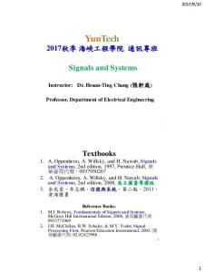
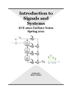
Autocorrelation rxx(l) of a Noiseless Periodic Signal
Noiseless Periodic Signal x(n)
1.5
100
1 50 r (l)
x(n)
0.5 xx
0 −0.5
0 −50
−1 −1.5
0
20
40 n
60
−100 −100
80
0 l
50
100
Autocorrelation r (l) of a Noisy Signal
Noisy Periodic Signal y(n)
4
−50
yy
200 150 100 r (l)
0
50
yy
y(n)
2
0 −50
−2
−100 −4
0
20
40 n
60
80
−150 −100
−50
0 l
50
100
Figure 2.1: Example of autocorrelation of a periodic signal with a noisy signal having the same dominant frequency component.
c J. Fessler, May 27, 2004, 13:10 (student version)
2.7
2.2 Discrete-time systems A discrete-time system is a device or algorithm that, according to some well-defined rule, operates on a discrete-time signal called the input signal or excitation to produce another discrete-time signal called the output signal or response. Mathematically speaking, a system is also a function. The input signal x[n] is transformed by the system into a signal y[n], which we express mathematically as T y[·] = T {x[·]} or y[n] = T {x[·]}[n] or x[·] → y[·] .
The notation y[n] = T {x[n]} is mathematically vague. The reader must understand that in general y[n] is a function of the entire sequence {x[n]}, not just the single time point x[n]. Input Signal Output Signal → Discrete-time system → x[n] y[n]
2.2.1 Input-output description of systems A discrete-time system can be described in many ways. One way is by its input-output relationship, which is a formula expressing the output signal in terms of the input signal. Example. The accumulator system. Pn y[n] = k=−∞ x[k] = x[n] + x[n − 1] + x[n − 2] + · · · x[n] = u[n] − u[n − 3] = {. . . , 0, 0, 1, 1, 1, 0, 0, . . .} y[n] = {. . . , 0, 0, 1, 2, 3, 3, . . .} . Example 2.2.1(f) on p.58 has error. Pn Pn−1 Alternative expression: y[n] = k=−∞ x[k] = k=−∞ x[k] + x[n] = y[n − 1] + x[n]
Example. Interest-bearing checking account with monthly fee: y[n] = 1.01 y[n − 1] + x[n] −2 u[n] . Why the u[n]? Notice the relevant “physical” quantities (interest rate, fee, balance) are captured in this mathematical expression. The field of “Systems” deals with mathematical modeling of (more or less) “physical” things.
read about initial condition and initially relaxed 2.2.2 Block diagram representation of discrete-time systems Example. 0.5
x(n)
y(n)
−1
−1
z
• • • •
y(n−1)
x(n−1)
z
y(n) = y(n−1) x(n−1) + 0.5 x(n) adder constant multiplier signal multiplier unit delay element (why z −1 clear later) In real-time hardware, each delay element requires 1 signal sample worth of memory (to store each sample until the next arrives). How are delays implemented? With buffers / latches / flip-flops.
Other representations to be discussed later (mostly for LTI systems). • Difference equation • Impulse response • System function • pole-zero plot • Frequency response
c J. Fessler, May 27, 2004, 13:10 (student version)
2.8
2.2.3 Classification of discrete-time systems Skill: Determining classifications of a given DT system Two general aspects to categorize: time properties and amplitude properties. Time properties (causality, memory, time invariance) Causality For a causal system, the output y[n] at any time n depends only on the “present” and “past” inputs i.e., y[n] = F {x[n], x[n − 1], x[n − 2], . . .} where F {·} is any function.
Causality is necessary for real-time implementation, but many DSP problems involved stored data, e.g., image processing (OCR) or restoration of analog audio recordings.
Otherwise noncausal system. Memory • For a static system or memoryless √ system, the output y[n] depends only on the current input x[n], not on previous or future inputs. Example: y[n] = ex[n] / n − 2. • Otherwise it is a dynamic system and must have memory. Dynamic systems are the interesting ones and will be our focus. (This time we take the more complicated choice!) Is a memoryless system necessarily causal? Yes. But dynamic systems can be causal or noncausal. Time invariance Systems whose input-output behavior does not change with time are called time-invariant and will be our focus Why? “Easier” to analyze. Time-invariance is a desired property of many systems. A relaxed system T is called time invariant or shift invariant iff T
T
x[n] → y[n] implies that x[n − k] → y[n − k] for every input signal x[n] and integer time shift k. Otherwise the system is called time variant or shift variant. Graphically: x[n]
→
delay z −k → system T → y[n]
x[n]
→
system T → delay z −k → y[n]
Recipe for showing time-invariance. (This method avoids potentially confusing y(n, k) notation.) • Determine output y1 [n] due to a generic input x1 [n]. • Determine output y2 [n] due to input x2 [n] = x1 [n − k]. • If y2 [n] = y1 [n − k], then system is time-invariant.
Example: 3-point moving average y[n] = 31 (x[n − 1] + x[n] + x[n + 1]) . Time invariant? yes. • Output due to x1 [n] is y1 [n] = 31 (x1 [n − 1] + x1 [n] + x1 [n + 1]) . • Output due to shifted input x2 [n] = x1 [n − k] is y2 [n] = 31 (x2 [n − 1] + x2 [n] + x2 [n + 1]) = 13 (x1 [n − k − 1] + x1 [n − k] + x1 [n − k + 1]) • Since y1 [n − k] = 13 (x1 [n − k − 1] + x1 [n − k] + x1 [n − k + 1]) = y2 [n], the system is time-invariant.
Example: down-sampler y[n] = x[2n]. Time invariant? no. How do we show lack of a property? Find counter-example. If x[n] = δ[n] then y[n] = δ[n]. If x[n] = δ[n − 1] then y[n] = 0 6= δ[n − 1]. Simple counterexample all that is needed. We will focus on time-invariant systems.
c J. Fessler, May 27, 2004, 13:10 (student version)
2.9
skip Here is another mathematical way of expressing time invariance. If y[n] = F {n, x[m1 (n)], x[m2 (n)], . . .} for some functions mj : Z → Z, then the system is time-invariant iff for any signal x[n]: F {n − k, x[m1 (n − k)], x[m2 (n − k)], . . .} = F {n, x[m1 (n) − k], x[m2 (n) − k], . . .} ∀n, k ∈ Z. The left side is “shifting the output” whereas the right side is “shifting the input.” “Amplitude” properties (stability, invertibility, linearity) Invertibility A system T is invertible if every output signal corresponds to a unique input signal. If so, then there exists an inverse system T that can recover the input signal: x[n] → T → y[n] → T −1 → x[n] .
−1
We will derive tests for invertibility later. Stability
A system is bounded-input bounded-output (BIBO) stable iff every bounded input produces a bounded output. If ∃Mx s.t. |x[n]| ≤ Mx < ∞ ∀n, then there must exist an My s.t. |y[n]| ≤ My < ∞ ∀n. Usually My will depend on Mx . Example: accumulator y[n] = y[n − 1] + x[n]. Consider input signal x[n] = u[n], which is bounded by M x = 1. But y[n] = n + 1 + y[−1] blows up, so the accumulator is an unstable system. We will derive a simple test for BIBO stability shortly.
Linearity We will also focus on linear systems. Why linearity? • The class of linear systems is easier to analyze. • Often linearity is desirable - avoids distortions. • Many nonlinear systems are approximately linear, so first-order analysis is linear case. A system T is linear iff
T
T {a1 x1 [n] +a2 x2 [n]} = a1 T {x1 [n]} +a2 T {x2 [n]}, i.e., a1 x1 [n] +a2 x2 [n] → a1 y1 [n] +a2 y2 [n], for any signals x1 [n], x2 [n], and constants a1 and a2 . Otherwise the system is called nonlinear.
c J. Fessler, May 27, 2004, 13:10 (student version)
2.10
Block diagram illustration of linearity test. x1 [n]
a1
T x2 [n] PSfrag replacements
y[n]
a2 a1
T
x1 [n]
y[n] a2
T
x2 [n]
Two important special cases of linearity property. • scaling property: T {a x[n]} = aT [x[n]] Note that from a = 0 we see that zero input signal implies zero output signal for a linear system. • additivity property: T {x1 [n] + x2 [n]} = T {x1 [n]} + T {x2 [n]} Using proof-by-induction, one can easily extend this property to the general superposition property: T
"
K X
k=1
#
xk [n] =
K X
k=1
T {xk [n]} .
In words: the response of a linear system to the sum of several signals is the sum of the response to each of the signals. In general superposition need not hold for infinite sums; additional continuity assumptions are required. We assume the superposition summation holds even for infinite sums without further comment in this course. Pn Example: Proof that the accumulator is a linear system, where y[n] = k=−∞ x[k]. Method: • Find output signal y1 [n] for a general input signal x1 [n]. • “Repeat” for input x2 [n] and y2 [n]. • Find output signal y[n] when input signal is x[n] = a1 x1 [n] +a2 x2 [n] . • If y[n] = a1 y1 [n] +a2 y2 [n], ∀n, then the system is linear. Pn Pn For the accumulator, y1 [n] = k=−∞ x1 [n] and y2 [n] = k=−∞ x2 [n]. If the input is x[n] = a1 x1 [n] +a2 x2 [n], then the output is y[n] =
n X
k=−∞
x[n] =
n X
(a1 x1 [n] +a2 x2 [n]) = a1
k=−∞
n X
k=−∞
x1 [n] +a2
n X
x2 [n] = a1 y1 [n] +a2 y2 [n] .
k=−∞
Since this holds for all n, for all input signals x1 [n] and x2 [n], and for any constants a1 and a2 , the accumulator is linear. p Example: To show that y[n] = x[n] is nonlinear, all that is needed is a counter-example to the above properties. The scaling √ property will usually suffice. √ Let x1 [n] = 2, a constant signal. Then y1 [n] = 2. Now suppose the input is x[n] = 3 x1 [n] = 6, then the output is y[n] = 6 6= 3 y1 [n], so the system is nonlinear. 2.2.4 Interconnection of discrete-time systems
skip essentially repeated in 2.3.4
c J. Fessler, May 27, 2004, 13:10 (student version)
2.11
2.3 Analysis of discrete-time linear time-invariant systems (Our focus is LTI hereafter) Why analysis? So far we only have input-output relationships. For a given system can compute y[n] for selected x[n]’s, but very difficult to design filters etc. by such trial-and-error. Overview: x[n] → LTI h[n] → y[n] = x[n] ∗ h[n]. Linearity leads to the above superposition property, which simplifies the analysis. Time-invariance then further simplifies. 2.3.1 Techniques for the analysis of linear systems General strategy: P • Decompose input signal x[n] into a weighted sum of elementary functions x k [n], i.e., x[n] = k ck xk [n] • Determine response of system to each elementary function (this should be easy from input-output relationship): T
xk [n] → yk [n] • Apply superposition property:
x[n] =
X k
T
ck xk [n] → y[n] =
X
ck yk [n] .
k
Two particularly good choices for the elementary functions xk [n]: • impulse functions δ[n − k] • complex exponentials eωk n (later). 2.3.2 Resolution of discrete-time signal into impulses
It follows directly from the definition of δ[n] that x[n] =
∞ X
k=−∞
x[k] δ[n − k] .
This is the sifting property of the unit impulse function. √ √ � Example. x[n] = 8, π, 0, 7 =⇒ x[n] = 8 δ[n − 0] +π δ[n − 1] + 7 δ[n − 3] . 2.3.3 Response of LTI systems to arbitrary inputs: the convolution sum
Define the special symbol hk [n] to denote the system output when the input is δ[n − k], i.e., T
δ[n − k] → hk [n] . In words: hk [n] is the response to an impulse at the kth sample. Now use superposition to determine the response to a general input signal x[n]: x[n] =
X k
T
x[k] δ[n − k] → y[n] =
X
x[k] hk [n] .
k
Thus we have proven the superposition summation for any linear system T : ∞ X T x[n] |{z} → y[n] = x[k] hk [n] . k=−∞ Linear
In words: overall output is weighted sum of response due to kth sample. Every input sample that comes into the system causes the system to respond. For a linear system, the overall response is the sum of the contributions due to each input sample.
c J. Fessler, May 27, 2004, 13:10 (student version)
2.12
We have not yet used time-invariance. If the system is time-invariant, then the response to a delayed impulse δ[n − k] is just a delayed version of the response to an impulse at time 0: δ[n]. Thus, for a LTI system: h k [n] = h0 [n − k] Thus for time-invariant linear systems, the superposition summation becomes y[n] =
∞ X
k=−∞
x[k] h0 [n − k] .
The “0” subscript is redundant, so we drop it and just write h[n − k] instead. We call h[n] the impulse response of the system. In summary, for an LTI system with impulse response h[n], the response to an arbitrary input is given by the convolution sum: T
x[n] |{z} → y[n] = LTI
∞ X
k=−∞
x[k] h[n − k] =
∞ X
k=−∞
4
x[n − k] h[k] = x[n] ∗ h[n] = (x ∗ h)[n].
The second equality, which implies that convolution is commutative, it obtained from the first by letting m = n − k so that we P have y[n] = m x[n − m] h[m] . Now just replace m with k since it is just a dummy summation argument and any letter (other than n...) will do. The convolution sum shows that with the impulse response h[n], you can compute the output y[n] for any input signal x[n]. Thus A LTI system is characterized completely by its impulse response h[n]. Example. If y[n] = a y[n − 1] + x[n], then (later we show that) h[n] = an u[n]. For the input x[n] = u[n], find the output y[n], which is called the unit-step response of the system. Assume a 6= 1. n 1 − an+1 X , a 6= 1 Now using the second convolution formula above: k First a useful fact. a = 1−a n+ 1, a = 1. k=0 y[n] =
∞ X
k=−∞
x[n − k] h[k] =
∞ X
k=−∞
k
u[n − k] a u[k] =
� Pn
k=0
0,
ak ,
1 − an+1 n≥0 = u[n] . otherwise 1−a
Picture . Inner terms nonzero only where k ≤ n and k ≥ 0, i.e., 0 ≤ k ≤ n. Thus nonzero only if n ≥ 0.
Sometimes the summation limits are less obvious, and one can use the following recipe for convolution. Skill: convolving • Fold: fold h[k] about k = 0 to get h[−k] • Shift: shift h[−k] by n to get h[n − k] • Multiply: x[k]Pby h[n − k] for every k ∞ • Sum: y[n] = k=−∞ x[k] h[n − k]
Repeat for all possible n; generally breaks in to a few intervals.
skip Graphically for above example Fold: h[−k] = a−k u[−k] Shift: h[n − k] = an−k u[n − k] Multiply: x[k] h[n − k] = u[k] an−k u[n − k], nonzero only for 0 ≤ k ≤ n and hence n ≥ 0. Sum: (using m = n − k) n n 1 − an+1 X X , a 6= 1 u[n] m n−k a = a = 1−a n+ 1, a = 1. m=0 k=0 as before.
Example: h[n] = δ[n − n0 ], showing that y[n] = x[n − n0 ]. What is the system with this impulse response called? A delay or shifter. Picture
c J. Fessler, May 27, 2004, 13:10 (student version)
2.13
2.3.4 Properties of convolution and the interconnection of LTI systems Skill: Use properties to simplify LTI systems. Awareness of these properties is necessary for efficient designs. Support If x[n] has support n = N1 , . . . , N1 + L1 − 1 (length L1 ) and h[n] has support n = N2 , . . . , N2 + L2 − 1 (length L2 ) then y[n] = x[n] ∗ h[n] has support n = N1 + N2 , . . . , N1 + L1 − 1 + N2 + L2 − 1 (length L2 ) What is the duration of y[n]? L = L1 + L2 − 1 Time-shift
x[n] ∗ h[n] = y[n]
x[n − n0 ] ∗ h[n] = y[n − n0 ] x[n − n1 ] ∗ h[n − n2 ] = y[n − n1 − n2 ]
=⇒
Commutative law x[n] ∗ h[n] = h[n] ∗ x[n]
Proof: x[n] ∗ h[n] = where k 0 = n − k.
∞ X
k=−∞
x[k] h[n − k] =
∞ X
k0 =−∞
x[n − k 0 ] h[k 0 ] = h[n] ∗ x[n],
Associative law
(x[n] ∗ h1 [n]) ∗ h2 [n] = x[n] ∗ (h1 [n] ∗ h2 [n])
Proof: let y1 [n] = (x[n] ∗ h1 [n]) ∗ h2 [n] and y2 [n] = x[n] ∗ (h1 [n] ∗ h2 [n]). We must show y1 [n] = y2 [n]. y1 [n]
=
∞ X
k=−∞
=
X l
(x ∗ h1 )[n − k] h2 [k] =
X X l
k
!
x[l] h1 [n − k − l] h2 [k] =
X
x[l]
l
X k
h1 [n − l − k] h2 [k]
!
x[l](h1 ∗ h2 )[n − l] = (x ∗ [h1 ∗ h2 ])[n] = y2 [n] .
The above laws hold in general for any number of systems connected in series. So the following notation is acceptable: h[n] = h1 [n] ∗ h2 [n] ∗ · · · ∗ hk [n] . In particular: (x ∗ h1 ) ∗ h2
= = =
x ∗ (h1 ∗ h2 )
x ∗ (h2 ∗ h1 ) (x ∗ h2 ) ∗ h1 ,
so the order of serial connection of LTI systems with impulse response h1 and h2 does not affect output signal. See picture. Distributive law Proof:
x[n] ∗ (h1 [n] + h2 [n]) = (x[n] ∗ h1 [n]) + (x[n] ∗ h2 [n]) x[n] ∗ (h1 [n] + h2 [n])
= =
∞ X
k=−∞ ∞ X
k=−∞
=
x[n − k] (h1 [k] + h2 [k]) x[n − k] h1 [k] +
∞ X
k=−∞
x[n − k] h2 [k]
x[n] ∗ h1 [n] + x[n] ∗ h2 [n] .
All of the above follow from simple properties of addition and multiplication due to LTI assumption.
c J. Fessler, May 27, 2004, 13:10 (student version)
2.14
Here are the above properties illustrated with block diagrams. Commutative
x[n] → h[n] → y[n]
yields same output!
h[n] → x[n] → y[n]
The order of interconnection of systems in series or cascade does not affect the output 2 . Associative
x[n] → h1 [n] → h2 [n] → y[n] x[n] → h1 [n] ∗ h2 [n] → y[n]
Commutative
x[n] → h2 [n] ∗ h1 [n] → y[n]
Associative
x[n] → h2 [n] → h1 [n] → y[n] Parallel connection: -
h1 [n] ? +
x[n] -
- y[n]
6 h2 [n]
Distributive: x[n] → h[n] = h1 [n] + h2 [n] → y[n] Example. x[n] → h1 [n] = δ[n] − δ[n − 1] → h2 [n] = u[n] → y[n] Overall impulse response: h[n] = h1 [n] ∗ h2 [n] = (δ[n] − δ[n − 1]) ∗ u[n] = u[n] − u[n − 1] = δ[n] . Convolution with impulses Time shift / delay: x[n] ∗ δ[n − n0 ] = x[n − n0 ] Identity: x[n] ∗ δ[n] = x[n] Cascade of time shifts: δ[n − n1 ] ∗ δ[n − n2 ] = δ[n − n1 − n2 ]
2 This claim only holds for ideal LTI systems based on real numbers. In digital systems where the signal values and filter coefficients are quantized, the order of interconnection can matter in some cases.
c J. Fessler, May 27, 2004, 13:10 (student version)
2.15
Properties of LTI systems in terms of the impulse response Since an LTI system is characterized completely by its impulse response, we should be able to express all of the other four properties (causality, invertibility, memory, stability) in terms of h[n]. 2.3.5 Causal LTI systems Recall system is causal iff output y[n] depends only on present and past values of input. For an LTI system with impulse response h[n]: y[n] =
∞ X
k=−∞
h[k] x[n − k] =
∞ X
k=0
h[k] x[n − k] +
−1 X
k=−∞
h[k] x[n − k] .
The first sum depends on present and past input samples x[n], x[n − 1], . . ., whereas the second sum depends on future input samples x[n + 1], x[n + 1], . . .. Thus the system is causal iff the impulse response terms corresponding to the second sum is zero. These terms are h[−1], h[−2], . . .. An LTI system is causal iff its impulse response h[n] = 0 for all n < 0. In the causal case the convolution summation simplifies slightly since we can drop the right sum above: y[n] =
∞ X
k=0
h[k] x[n − k] =
n X
k=−∞
x[k] h[n − k] .
Example. Is the LTI system with h[n] = u[n − n0 − 5] causal? Only if n0 + 5 ≥ 0. A causal sequence is a sequence x[n] which is zero for all n < 0. If the input to a causal LTI system is a causal sequence, then the output is simply � 0, Pn P y[n] = n k=0 h[k] x[n − k] = k=0 x[k] h[n − k],
n