This paper proposes a method for precise overlapping of projected images from multiple steerable projectors. When they are controlled simultaneously, two ...
Displaying a Moving Image By Multiple Steerable Projectors Ikuhisa Mitsugami Norimichi Ukita Masatsugu Kidode Nara Institute of Science and Technology {ikuhi-mi,ukita,kidode}@is.naist.jp
Abstract This paper proposes a method for precise overlapping of projected images from multiple steerable projectors. When they are controlled simultaneously, two problems are revealed: (1) even a slight positional error of the projected image, which does not matter in the case of a single projector, causes misalignments of multiple projected images that can be perceived clearly when using multiple projectors; and (2) as the projectors usually do not have architectures for their synchronization it is impossible to display a moving image that is by tiling or overlaying precisely the multiple projected images. To overcome (1), a method is proposed that measures preliminarily the misalignments through every plane in the environment, and hence displays the image without the misalignment. For (2), a consideration and a new proposal for the synchronization of multiple projectors are also discussed.
1. Introduction Technique for displaying visual information in the environment can be used in many applications: navigation [6], remote instruction [8], design simulation [7], and so on. In these days, projectors are often used for these display system; they can show images directly on surfaces in the environment and so observers are free from wearing any devices. However, as long as there is a single fixed projector in the environment, its projectable area is very restricted. This restriction can be overcome by introducing a rotatable mechanism; the projectable area is widely spread. In addition, if multiple steerable projectors are located with appropriate intervals, almost all the surfaces in the environment can be covered, and cooperation between them can offer a larger or brighter image than the capacity of a single projector, by tiling or overlaying multiple projections. This study aims at the realization of such a multiple steerable projector system. Several steerable projectors and their calibration methods have been developed [1, 2]. If every steerable projector is precisely calibrated by these methods, tiling and overlaying multiple projections are straightforward; we just input
the coordinates of the projection images so that they become tiled or overlaid. In fact, however, every projection image has slight positional errors, which are observed as relative misalignments when tiling and overlaying them. This paper proposes a method where a misalignment map is prepared preliminarily to avoid misalignment during use. Even after realizing the alignment of multiple projections, misalignment still occurs when a moving image has to be projected from multiple projectors. This is because of (1) nonconstant delays in calculating the projection image and in network communication, and (2) unsynchronized projections by the multiple projectors. This paper describes a synchronization method for network-connected multiple projectors based on the dynamic memory architecture [3] to realize the projection of well-aligned moving multiple images.
2. A FC-PT projector Among the existing steerable projectors, a FC-PT projector proposed in [4] is adopted in this paper. The FCPT projector (Fixed-Center Pan-Tilt projector) is a steerable projector designed so that its projection center coincides spatially with its rotation center. As its structure is less complicated and has less parameters to estimate, the intrinsic calibration can be executed more precisely and stably. Using the FC-PT projector, the intrinsic calibration can be executed precisely and stably due to the optimization method. Extrinsic calibration can also be executed stably because wider information about the plane can be used by the proposed calibration method than by existing methods for the fixed projector, (Zhang’s method [10], for example). Positional errors of projected images are adequately small, which correspond with only a few pixels of the projector. In fact, these positional errors are acceptable for many applications.
3. Alignment of Multiple Projections 3.1. Causes of Misalignment and Strategy There are several ways to achieve local alignment of multiple projections [5, 9], and most of them use homog-
raphy relations between the image planes and the plane in the real world, assuming its perfect flatness. In fact, when the planar region is not so large and can be regarded to be perfectly flat, such ways work precisely because a kind of optimization method can be applied based on the flatness. However, in the case of wide planes in the real world, flatness may not be fully achieved so that the optimization may yield a worse result. In these cases, a simpler way should be applied instead of such sophisticated approaches. To achieve this, the present section proposes a method that first samples misalignments on the plane and then estimates an alignment at any other position from the neighboring samples. Although these misalignments basically depend on both the image’s position on the plane and the orientations of the projectors, as long as the intrinsic calibration of the FC-PT projector is executed precisely the misalignment depends on only the image’s position. This approach, which does not consider the orientations, can thus be considered to be appropriate. A disadvantage of this method is that its application needs more time than that of the sophisticated one. However, this is not a serious issue because this timeconsuming task has to be executed only once, just after the FC-PT projectors are located. Note that in this method a pan-tilt-zoom camera is also used to detect local misalignment. The camera just needs a rough calibration; it just should be directed roughly to the position where the image is displayed in order to observe that area around the position.
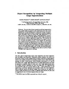
3.2. Generation of Misalignment Map The misalignment error of multiple projections depends on the position on the projected plane. Once the misalignment errors are preliminarily measured on the entire plane and saved as a misalignment map, a misalignment error at any position can be rectified by referring to the map. Since most planes in the real environment are not perfectly flat (slightly curved, for example), the misalignment errors have to be measured very densely. However, as long as the area being focused on is only a localized area it can be regarded as being flat, so that the map has to retain the errors only at discrete positions and interpolation is effective for other positions. The discrete positions are spaced at a certain interval d, and are called sampling positions S i,j , and the misalignment error at S i,j is defined as v i,j , where i, j are the indexes along the two dimensions of the plane. To robustly and precisely measure the misalignment v i,j by a camera, a grid pattern each of whose interval is d and which contains 3 × 3 points is used. Such a grid pattern is projected at S i,j so as that the center grid point corresponds with S i,j . Next, the projected grid patterns are observed by a pan-tilt-zoom camera. The orientation and zoom parameter of the camera is controlled according to the position of the projected image. As mentioned in 3.1, the camera just
(a) Captured image of pan-tilt-zoom camera
Divide into each channel (c) B channel
(b) R channel
(d)
Detect the grid points (e)
pi , j ,k
qi , j ,k
Overlay
Projected Plane coordinate
Qi , j ,k Homography
d Pk
Misalignment error
vi , j
Figure 1. Grid pattern projection at a sampling position.
needs to be calibrated roughly. Figure 1 (a) shows an example of the projected grid pattern. When using two projectors, by using different color channels for each projector, the two grid patterns can be detected simultaneously (Figure 1 (b),(c)), and then the grid points pi,j,k and q i,j,k in the camera image coordinate can be calculated (Figure 1 (d),(e)). When there are more projectors, this process is repeated for all the projectors while keeping the camera parameters. Next, the misalignment between pi,j,k and q i,j,k in the camera image is transformed into that of the plane in the real environment. By the homography relation, pi,j,k fulfills the following equation: x x pi,j,k Pk y y Pk = Hi,j pi,j,k , (1) 1 1 where Hi,j is a 3 × 3 matrix, and P k are the metric grid point coordinate. P 1 = (−d, −d), P 2 = (0, −d), P 3 = (d, −d), P 5 = (0, 0), P 6 = (d, 0), P 4 = (−d, 0), P 7 = (−d, d), P 8 = (0, d), P 9 = (d, d). (2) As pi,j,k are given from the observations by the camera, Hi,j is calculated using Equations (1) and (2). Then, Qi,j,k ,
Projector (V3-131, PLUS VISION Corp.) Projection System DLP Contrast ratio 2000:1 Brightness 1000lm Resolution XGA (1024 !_ 768) Weight 1.1kg Rotatable stage Rotation range (pan) –60 ∼ 60 deg Rotation range (tilt) –30 ∼ 30 deg Accuracy (pan and tilt) 0.01 deg Rotation speed 10 deg/s Weight 10 kg
vi +1, j
vi , j
Si , j
Si +1, j
l
m
T
u
d
vi +1, j +1
vi , j +1 Si +1, j +1
Si , j +1
Figure 2. Alignment by interpolation.
Table 1. Specification list of the FC-PT projector.
Pan axis
which are the grid points on the plane determined the other projector, are also calculated from q i,j,k . x x qi,j,k Qi,j,k y Qyi,j,k = Hi,j qi,j,k . (3) 1 1 Considering that the misalignment consists of translation, the misalignment v i,j at the position S i,j is obtained by the following equation: v i,j =
1� (Qi,j,k − P k ). 9
(4)
k
Projector
Figure 3. FC-PT projector.
Pan-tilt-zoom camera
Note that, using a pan-tilt-zoom camera, the process above can be executed automatically. This steerable camera only needs to be roughly calibrated to be adequately directed to the position of the projected pattern.
3.3. Precise Alignment Using the Misalignment Map Once the misalignment map v i,j is obtained, the translation for the alignment at any position (T x , T y ) can be calculated by the following interpolation: u
=
l(d − m) (d − l)(d − m) v i,j + v i+1,j 2 d d2 (d − l)m lm + v i,j+1 + 2 v i+1,j+1 , 2 d d
Tilt axis
1200mm
Image Projec ted
plane
2400m m
FC-PT projector
Figure 4. Experimental environment.
(5)
where i, j are the maximum integer numbers that fulfill the following equation: Tx Ty
x = Si,j +l
=
y Si,j
+m
(a) Not aligned.
(0 < l < d), (0 < m < d).
(6)
This translation u should be applied for one projector to cancel the misalignment.
3.4. Experimental Results Figure 4 shows the experimental environment. Two FCPT projectors and a pan-tilt-zoom camera were used. The
(b) Aligned.
Figure 5. Effect of the alignment method.
specification of the FC-PT projector is shown in Tables 1. For the projected plane, we used a 1200 mm × 2400 mm board that was slightly curved. The sampling interval d of the misalignment map was 200 mm. To confirm the effectiveness of the proposed alignment
Operator PC
Input device Camera
LAN
1600mm
Receiver PC
FC-PT projector Figure 6. Larger image projection by tiling multiple projections.
(a) Projection by one projector.
(b) Projection by two projectors.
Figure 7. Bright clear image obtained by overlaying multiple projections.
method, the two projection results were compared with each other; one was obtained only by the FC-PT projector calibration and the other was rectified by the misalignment map. Note that the images from two projectors were overlaid in both results. Although the misalignments were adequate large, whose maximum was 22 mm, they were much reduced to about one millimeter. Figure 5 shows an example of the result; (a) included 10 mm translation errors, which prevented us from observing the image naturally, while (b), rectified by the proposed method, looks natural. The effects of tiling and overlaying multiple projections were also examined. Figure 6 shows a large image displayed by tiling two projections. The image had 1600 mm width while the maximum projection width of each projector was 1200 mm. Figure 7 shows an example of overlaying multiple projections. It was found that by overlaying them the image became bright and clear even when the brightness of each projector was not enough.
4. Synchronization of Multiple Projectors 4.1. Configuration for Controlling Multiple Projectors As long as the multiple steerable projectors are used independently, no architecture is needed to integrate them. However, it may be desirable that the multiple projectors
Figure 8. Configuration for multiple projectors.
collaborate to move the image widely in the environment, or to have the ability to display a larger or brighter image by tiling or overlaying the multiple projections. To construct a system using multiple projectors, two kinds of architectures are considered; one consists of multiple projectors and a single computer that controls all the projectors, and the other uses multiple computers each of which controls a corresponding projector. The former can easily control the projectors, and this architecture can work well as long as there are only a few projectors, as mentioned in [9]. It is not good, however, for scalability; the calculation load of the computer increases in proportion to the number of projectors. In practice, in many applications, the number of projectors is decided according to the size and shape of the environment and they are usually located separately with adequate long intervals, around several meters in the environment for example, so that the scalability is very important requirement. For these reasons, the latter architecture is applied in this paper. In this architecture, the multiple computers are connected to a network. To operate the projectors for the applications, there has to exist information about the image that is expected to be displayed, so that a computer for treating the information is also needed in the network1 , as shown in Figure 8. This computer is called an “operator PC”, and the other computers for the controlling the projectors are called “receiver PCs.” The information treated by the operator comes from various sources, which depend on the applications. In a human navigation system, for example, the information is the position of the human and so obtained by a sensing system such as a camera system in the environment. In another case, when the system is used simply as a virtual TV monitor for personal use, the information is input from some input devices. 1 The computer may be one of the computers being used for the projectors.
The receivers get the information transmitted from the operator. Because the projectors may be located separately and at large distances from one another, the network transmission times from the operator to the receivers may be different according to the distances. Even when all the distances are similar to one another, their handling timing may be different from one another.
Operator
vn
vn +1
vn + 2
vn + 3
Sequence of a variable
Operated
Time t
tn
tn +1
tn + 2 t n+3 vn
Receiver
Problem 3 Problem 1
Received
Time t '
Transmission delay ∆t 'Trans
4.2. Transmitted Data What information is communicated in the network should be considered. In the system proposed, every FCPT projector is calibrated separately using global coordinates. Moreover, once the calibration is executed, every receiver can control the corresponding FC-PT projector independently only from variables about the image: its width, height and orientation in the environment, which are called image parameters. Therefore, the operator simply transmits the image parameters to all the receivers. Although in this configuration the operator does not manage a control state of each projector, it has the advantage of scalability; even when the number of the projectors is changed, the transmitted data does not change at all.
Displayed
Problem 2
Time t '
Calculation delay ∆t 'Calc
Figure 9. Problems in using multiple projectors.
value interpolated
predicted v(T1)
t1
t2 t3
t4 t5 T1
4.3. Real Time Integration of Multiple Projectors
time
t6 Now T2
Figure 10. Dynamic memory.
4.3.1 Problem of Integrating Multiple Projectors As long as a position and size of an image are fixed, the system works well; every projected image is displayed at an adequately accurate position, and then the misalignment between the projected images is cancelled by the method in this paper. However, in the case of a moving image, it does not work adequately. Figure 9 shows problems in the case. In this figure, the horizontal axis denotes time and the vertical one denotes a value of one of the image parameters. Problem 1 — Delay of data transmission: The variables of the displayed image are transmitted from the operator to the receivers through the network. This data transmission time and the handling timing may be different from one another. Problem 2 — Delay of calculation: Having acquired the variables of the image, the receiver calculates the input image and orientation of the corresponding projector. These calculation times vary depending on the size of the input image and the CPU and GPU abilities of the receivers, so that they are usually different from one another. Problem 3 — Asynchronization of multiple projectors: The projectors usually run asynchronously; every projector works based on its own clock and frame rate. Section 4.4 gives detailed discussion of this problem.
In constructing multiple camera systems similar problems have arisen in other studies. Matsuyama et al. considered these problems and proposed a new architecture in [3], which is called “dynamic memory.” This architecture overcame Problem 1 and Problem 3. Problem 2 was not considered because it is peculiar to projectors; in the camera system there is no calculation time for generating the projection image. This paper, therefore, modifies this dynamic memory architecture to take into account the delay of calculation. 4.3.2 Dynamic Memory In [3] the dynamic memory architecture was proposed for dynamic integration of multiple steerable cameras, which were called AVAs (Active Vision Agents) and had three modules: (1) visual perception, (2) action and (3) network communication. In the dynamic memory architecture, multiple parallel processes of the these above modules share what is called the dynamic memory. The read/write operations from/to the dynamic memory are defined as the following: Write operation: When a process computes a value v for a variable at a certain moment t, it writes (v, t) into the dynamic memory. Since such computation is repeated
according to the dynamics of the process, a discrete temporal sequence of values is recorded for each variable in the dynamic memory (a sequence of black dots in Figure 10). Note that since the speed of the computation varies depending on input data, the temporal interval between a pair of consecutive value becomes irregular.
Virtual Synchronization
Operator
vn +1
vn
vn + 2
Sequence of a variable Time t
Operated
t n t n +1 t n + 2 t n +3 ( vn , t n )
Receiver
vDisp
Received
Read operation A read process runs in parallel to the write process and tries to read the value of the variable at a certain moment from the dynamic memory: for example, the value at T1 in Figure 10. When no value was recorded at the specified moment, the dynamic memory interpolates it from its neighboring recorded discrete values. With this function, the reader process can read a value at any moment. In the case that the reader process runs fast and require data which are not yet written by the writer process (for example, the value at T2 in Figure 10), the dynamic memory predicts an expected value in the future based on those data so far recorded and returns it to the reader process.
vn +3
tn
t n +1
Predicted value t Disp = (t Now + ∆t Calc )
Synchronized by NTP Time t
vDisp Displayed
∆t Calc t Now
Time t
t Disp
Figure 11. Virtual synchronization of multiple projectors using dynamic memory architecture.
tDisp = tNow + ∆tCalc , as shown in Figure 11. ∆tCalc is determined by the previous frame, and the image parameters at tDisp can be obtained by the read operation of the dynamic memory.
With the above described functions, each process can get any data at any moment. That is, the dynamic memory integrates parallel processes into a unified system. This asynchronous module interaction capability is highly effective for the implementation of a real time system. In addition, the dynamic memory supports virtual synchronization between the multiple PCs. This virtual synchronization is achieved the following procedure. All PCs are first synchronized by NTP, and a timestamp L which indicates when the data should be processed is added to all transmitted data. Next, in the process of the network communication module, the write function writes not (v, t) but (v, L). As the clocks of the PCs are synchronous, the time L for each PC indicates an identical time, so that the sequence of v for each PC is virtually synchronous. This function overcomes Problem 1 and Problem 3 in Section 4.3.1.
4.4. Consideration about Synchronization
4.3.3 Applying Dynamic Memory to Multiple Steerable Projectors
Keeping the above in mind, this section discusses the importance of the synchronization of frames in multi-camera and multi-projector systems.
In the multiple projector system, there are also three modules, where the action and network communication modules are the same as those in the camera system but the visual perception module is replaced by an image calculation module. The dynamic memory architecture essentially allows them to run asynchronously and thus realizes virtual synchronization between the multiple projectors. However, a modification is necessary to fit fully this architecture to the multiple projector system; in the image calculation module, when the image calculation of the next frame of the projector begins at tNow , the corresponding image parameters should not be those at tNow but those at
4.4.1 Two Definitions of Synchronization The word “synchronization” for cameras and projectors has the following two meanings: • Synchronization of frames: This means making multiple cameras capture images at the same moment. In most camera systems, this definition is used. In the case of projectors, however, it means making multiple projectors project images at the same time. • Virtual synchronization of continuous sequences: This does not consider timing of capturing or projecting, but means making sequences of variables for them run in unison.
4.4.2 Synchronization of the Multi-camera System Multiple cameras are often used to obtain 3D shapes in the real world using the stereo vision or the volume intersection method. In these situations, it is very important that images of the multiple cameras at every capture have to be captured at the same time. If this is not achieved, moving objects cannot be measured precisely. The capture rate of every camera should be increased to record more detailed changes of the scene, but a higher priority should be put on realizing the frame synchronization,
Discrete images Continuous sequence
Camera 1
Time t
Camera 2
Time t Both should be captured simultaneously to be used in the stereo vision or the volume intersection method.
Figure 12. Discrete capture of a continuous scene. Discrete images Desired continuous sequence Projector 1
Time t
Projector 2
Time t
Figure 15. Moving image projection using two FC-PT projectors.
The image keeps unchanged in the interval.
Figure 13. Frame synchronization in the case of projectors.
Projector 1
Projector 2
Discrete sequence
Desirable continuous sequence Time t
Time t As the rate is higher, the discrete sequence looks increasingly similar to the desired continuous sequence.
Figure 14. Generating a continuous sequence by the discrete frames.
as mentioned above; even if the rate gets a little lower because of waiting times for capture by the cameras, frame synchronization should be maintained. This argument can be supported by the explanation below from another viewpoint. The images captured by the camera are discrete, as shown in Figure 12; the scene is divided into multiple still images. The camera is, therefore, regarded as a device that samples discrete values (corresponding to still images) from a continuous sequence (corresponding to the scene). To record the continuous sequence more precisely, the rate of sampling should be higher. However, according to the Nyquist-Shannon sampling theorem, twice the maximum frequency in the sequence is enough as the capture rate to recover the sequence perfectly; the rate does not need to be higher than that. 4.4.3 Synchronization of the Multi-projector System In contrast with cameras, projectors can be regarded as devices that transform discrete images to a continuous scene in the real world. However, this transformation cannot be fulfilled perfectly because the projector projects a still image discretely and keeps it in its frame interval as shown in
Figure 13. Although the sequence of the discrete images looks similar to the desired continuous sequence as shown in Figure 14 when the rate gets higher, it can never coincide perfectly with the continuous one. This means that in the case of the projector there is no sufficient rate; the rate should be increased as much as possible. Considering above, increasing frame rate of a projector is more important than for a camera, and when integrating multiple projectors a higher priority should be put on accomplishing the as high frame rate as possible; the frame synchronization, which is more important in the case of cameras, is less important. This paper, therefore, does not consider frame synchronization of multiple projectors but implements asynchronous projection, where every projector projects at its maximum frame rate.
4.5. Experiments Projection experiments were executed using two FC-PT projectors. The experimental environment is the same as in Section 3.4. The alignment method was applied the projected plane, and the sampling interval d of the misalignment map was 200 mm. Note that in the implementation the projector’s orientation is controlled by the stop-and-go method because of the limitation of the rotation stage, whereas in [3] orientation was smoothly and precisely controlled by the PID method. Figure 15 shows the results, where an image of a car is displayed by overlaying two projections at the same position. Two quadrangles around the car indicate the projectable area of the projectors. It was observed that the two projections remained well-aligned while the car image moved on the wall in a circle. Sometimes the misalignment was observed and it only occurred when each projector began or stopped its rotation. The cause of the misalignment is failure of the stage orientation estimation; when be-
jecting from different positions, the surfaces of the 3D object can be kept fully covered without any occluded regions. However, in fact, all existing studies such as [7, 8] for 3D object projection have been applied only to fixed objects. By extending the proposed integration method of multiple steerable projectors, a novel method for moving 3D objects will be studied. In addition, photometric calibration for multiple projections and 3D shape measurement system by the FC-PT projectors are also important topics.
14 12
)m10 (mt 8 enm ngi 6 la isM 4 2 0
0
5
10
15 Time (sec)
20
25
30
Figure 16. Misalignment when the image moves along a circle.
ginning or stopping the rotation, the variables change suddenly. If the PID method is adopted so that the stage moves smoothly, misalignment can be much reduced. Experiments for quantitative evaluation were also executed. Chessboard patterns were projected instead of the car image at the same position from the two FC-PT projectors and were tracked by a zoom camera to measure their misalignments. Figure 16 show the result in the case of circular paths on the wall. In the graph, the horizontal axis is time and the vertical axis is the misalignment. Although several peaks caused by the stage orientation estimation failure are observed in these graphs, it is confirmed that the system worked well; the misalignments stayed around one millimeters except these peaks. It was also confirmed that the frame rate of each projector is adequately high: 60 fps, which is the maximum rate of the device. Such a high rate was achievable because the system was implemented so as to put a higher priority not on fulfilling frame synchronization but on increasing the high frame rate. It was observed that the movement of the image looked very smooth due to this high rate.
5. Concluding Remarks This paper proposed a method that cancels misalignments between multiple projections for precisely tiling and overlaying them. The method measures misalignment of projected images through a plane in the environment and hence displays images without misalignment. This paper also describes a virtual synchronization method based on the dynamic memory architecture. It was confirmed that, using the method, the projection of well-aligned moving multiple images could be achieved. It was also confirmed that, because each projector can run at its maximum frame rate, the movement of the image looks very smooth. Future work includes projection onto moving objects. Projection from multiple projectors is thought to be more effective when projecting onto moving 3D objects; by pro-
References [1] M. Ashdown and Y. Sato. Steerable projector calibration. In International Workshop on Projector-Camera Systems (ProCams2005). IEEE Computer Society Press, 2005. 1 [2] S. Borkowski, O. Riff, and J. L. Crowley. Projecting rectified images in an augmented environment. In International Workshop on Projector-Camera Systems (ProCams2003). IEEE Computer Society Press, 2003. 1 [3] T. Matsuyama, S. Hiura, T. Wada, K. Murase, and A. Yoshioka. Dynamic memory: Architecture for real time integration of visual perception, camera action, and network communication. In Proc. IEEE Computer Society Conference on Computer Vision and Pattern Recognition (CVPR2000), volume 02, page 2728, Los Alamitos, CA, USA, 2000. IEEE Computer Society. 1, 5, 7 [4] I. Mitsugami, N. Ukita, and M. Kidode. Multi-planar projection by fixed-center pan-tilt projectors. In International Workshop on Projector-Camera Systems (ProCams2005). IEEE Computer Society Press, 2005. 1 [5] T. Okatani and K. Deguchi. Autocalibration of an ad hoc construction of multi-projector displays. In International Workshop on Projector-Camera Systems (ProCams2006). IEEE Computer Society Press, 2006. 1 [6] C. Pinhanez, R. Kjeldsen, A. Levas, G. Pingali, M. Podlaseck, and N. Sukaviriya. Applications of steerable projector-camera systems. In International Workshop on Projector-Camera Systems (ProCams2003). IEEE Computer Society Press, 2003. 1 [7] R. Raskar, G. Welch, K.-L. Low, and D. Bandyopadhyay. Shader lamps: Animating real objects with image based illumination. In Proc. 12th Eurographics Workshop on Rendering Workshop, pages 89–102, 2001. 1, 8 [8] K. Tojo, S. Hiura, and S. Inokuchi. 3-d tele-direction interface using video projector. Journal of the Virtual Reality Society of Japan, 7:169–176, 2002. (written in Japanese). 1, 8 [9] R. Yang, D. Gotz, J. Hensley, H. Towles, and M. S. Brown. Pixelflex: a reconfigurable multi-projector display system. In VIS ’01: Proceedings of the conference on Visualization ’01, pages 167–174, Washington, DC, USA, 2001. IEEE Computer Society. 1, 4 [10] Z. Zhang. A flexible new technique for camera calibration. IEEE Transactions on Pattern Analysis and Machine Intelligence, 22(11):1330–1334, 2000. 1