Distributed Energy Resources (DER) Object Modeling with IEC 61850-7-420 Taha Selim Ustun, Cagil Ozansoy, Aladin Zayegh School of Engineering and Science, Victoria University, Melbourne - Australia (email:
[email protected]) Abstract— The electrical networks are receiving more deployments of Distributed Energy Resources (DERs). In order to control the impact of DERs on existing networks, it is proposed to divide them into more manageable smaller sets which are called ‘microgrids’. Unlike conventional utility grids, microgrids include generators, storage devices and loads at all levels of the system. Power generation, distribution and consumption levels are not discrete and power flow may occur at any direction. At any point in time, the microgrid may become isolated from the utility grid and continue its operation under islanding conditions. Furthermore, some microgrids may have changing structures with alternative paths and the coupling point for a device or a part of the microgrid may change due to the altering conditions. In order to sustain a safe operation in such a versatile and dynamic structure which has numerous parameters and variables, a new management strategy that has communication lines is required. The need of an extensive communication between the microgrid components is widely accepted in the Power Engineering field. In an effort to standardize the communication methods and modeling IEC 61850 is issued by International Electrotechnical Commission. Currently, there are studies underway to extend this standard with IEC 61850-7-420 so that DERs are also modeled in a standard way. This paper focuses on the communication challenges in a microgrid system, a review of IEC 61850 and the implementation of IEC 61850-7-420 for DER modeling. Keywords- distributed generation, microgrid control, power system communication, communication standards,
I.
INTRODUCTION
The increased concerns for the environmental impacts of centralized coal-fired generation, most importantly those that relate to high CO2 emissions, are the main factors driving the transition towards small-scale decentralized generation of power. Decentralized (distributed) generation of electricity most favorably occurs from renewable sources that are located on the distribution system close to the point of consumption. Governments and industries all around the world are increasingly looking for ways to reduce the greenhouse emissions from their operations with a major focus on the use and installation of sustainable distributed energy systems [1]. The search for alternative energy sources and more efficient utilization of the energy as a means of tackling the global warming concerns will require fundamental changes in the Electrical Engineering (EE) field explicitly in relation to the matters associated with the Transmission and Distribution (T&D) of this renewable electricity. Although T&D grids have been around for many decades, Distributed Generation (DG) and Renewable Energy (RE) concepts have recently become
irreversibly popular. As a result, many research and development needs have evolved as a necessity to enable the scaling up of the implementation and uptake of renewable energy systems giving them recognition and equal status in energy sector investment processes. The trend is to increase the share of DG in the electricity supply. DG may also comprise Renewable Energy (RE) systems such as solar, wind and wave, which are promising cleaner technologies leading to reductions in greenhouse gas emissions and in effect aiding in the remedy of the global warming problem [2]. Consequently, governments and energy regulation authorities worldwide are encouraging more deployments of RE based Distributed Generator Systems (DGs). However, higher penetration of micro-sources, i.e. small scale PV panels, wind turbines, and diesel generators into the grid changes the traditional “radial” structure of the grid. This revolutionary change in the structure triggers many problems which were previously unknown to the grid operators and power engineers [3]. There are now various microsources at different penetration levels in the grid and this new structure invalidates the traditional power flow control methods. Moreover, DGs also make contributions to the fault currents around the network. Hence, in case of a fault, the transient characteristics of the network become completely different [4]. These are only a few of the issues that have arisen in relation with the revolutionary changes occurring in the grids and the way they are operated. There are still many technical challenges that must be overcome so that DGs can be cost-effectively, efficiently and reliably integrated into existing electric power systems. [5-7]. Therefore microgrids have been proposed which are small entities in a power system network, are capable of coordinating and managing DGS in a more decentralized way thus reducing the need for the centralized coordination and management of such systems [8]. This paper presents the necessity of a centralized microgrid management system which constantly monitors and communicates with the microgrid components, the communication strategy and standardization which are required therein and the international Standard IEC 61850 and its recent extension for DERs, i.e. IEC 61850-7-420. The organization of this paper is as follows: Section (II) summarizes the central microgrid management system with communication modules, Section (III) discusses the IEC 61850 communication standard, Section (IV) explains the IEC 618507-420 extension which is aimed at modeling distributed energy resources. Finally, Section (V) presents Futurework while Section (VI) draws the conclusions.
Figure 1. A sample microgrid
II.
CENTRAL MANAGEMENT SYSTEMS IN MICROGRIDS
Microgrids have dynamic structures which change very often. The following may be counted among the reasons for the changes in the microgrid structure: • New DG or load deployments • Islanding of the system • Fault conditions • Reconfiguration of the structure for reasons such as maintenance This dynamic behavior of microgrids is a major management challenge from power flow, control and protection perspectives. Whenever a restructuring occurs, the power generation, load sharing, control and protection strategies assigned prior to that become erroneous. For a proper operation, these parameters should follow the changing conditions of the network. This requires a centralized management system which implements an algorithm which will determine the current structure of the system and yield the relay hierarchy at all branches of the network. Consider the system shown in Figure 1. In this network, all branches have generation and load, and various alternative network structures can be formed through the combination of relays. As first case, assume that the circuit breakers CB1, CB2, CB3, CB4, CB6 and CB7 are closed whereas CB5 remains open. The power flow, load sharing, stability
parameters and protection schemes need to be adjusted accordingly. In this network structure, various DGs and loads can be connected to and disconnected from the microgrid. This required minor adjustments on the above mentioned factors. However, if CB4 is disconnected for any reason, for example maintenance or breakdown, CB5 closes in order to keep the integrity of the network. The line between Load 1 and Load 2 (protected by CB5) has therefore been added to form a loop structure when necessary and protect the microgrid against contingencies and failures. The whole network structure and the relationship between the microgrid components change significantly. This would require major adjustments on the power flow, load sharing, stability parameters and protection schemes to ensure satisfactory and safe operation. Therefore, a centralized microgrid management system which implements extensive communication with microgrid components is required. This management system will monitor DGs, loads, storage devices along with protection equipment and assign necessary parameters for respective component. The continuous monitoring and adjusting microgrid parameters onthe-fly help implement a dynamic management system required by the highly variable nature of the microgrids. Figure 2 shows a sample central management system that proposed communication lines between microgrid components and a central management unit. The central control units require permanent communication with the respective components.
Figure 2. A sample central microgrid management system
III.
STANDARDIZED COMMUNICATION WITH IEC 61850
IEC 65850 is an international standard for substation automation that has started out as the Electric Power Research Institute’s (EPRI’s) UCA 2.0. IEC 61850 is bound to have a significant impact on how electric power systems are to be designed and built for many years to come. It effectively reduces the diversity and complexity of utility automated solutions minimizing operating, maintenance and engineering costs. The model-driven approach of the IEC 61850 standard describes the communication between devices in a substation and the related system requirements. It supports all substation functions and their engineering by using Object Oriented (OO) data models that describe the processes to be implemented and controlled, e.g., the functionality of a circuit breaker or a feeder equipment etc. The use of the OO approach gives more flexibility to the developer and the user simplifying engineering tasks. IEC 61850 contains device models that describe the properties and allocation of functions in a physical device. In addition to the OO data models, it defines a set of generic services for the client/server interactions between devices in a substation and for the transfer of all sorts of data with respect to transmission requirements such as speed, reliability, and security. The Generic Object Oriented Substation Event (GOOSE) is widely accepted as the most important one of the data transmission services defined in IEC 61850. GOOSE is a fast connection-less communication service used for the transfer of time critical data where high speed and security are achieved by the repetition of messages a number of times. One of the most significant architectural constructs of the IEC 61850 is the adoption of an “abstracting” technique, which involves the creation of objects that are independent of any
underlying protocol. The isolation of the information models and information exchange services from the underlying on-thewire protocols is usually seen as one of the most powerful capabilities of the IEC 61850 standard. Abstract means that the standard focuses on describing what the services are indented to provide rather than how they are build. The abstract nature of the definitions permits the mappings of the data objects and services to any other protocol, which provides adequate communication procedures meeting the data and service requirements of the IEC 61850 standard. Currently, IEC 61850 only specifies mappings on a communication stack that includes the Manufacturing Message Specification (MMS) over the Transmission Control Protocol/Internet Protocol (TCP/IP) and Ethernet. However, the potential need to support mappings to different communication models has clearly been recognized in the industry and examples do exist in the literature detailing such mappings. Although not addressed in IEC 61850, it is possible to implement the standard’s object models and services by mapping to other different communication stacks such as the Distributed Component Object Model (DCOM) or Common Object Request Broker Architecture (CORBA). Substation Automation Systems (SASs), used for controlling substations, are usually composed of a number of Intelligent Electronic Devices (IEDs) interconnected through a network of high-speed communications with widespread routers and switches [9]. IEC 61850 has the objective of enabling interoperability between IEDs within a substation by defining standard object (information) models for IEDs and functions within a SAS [10]. As a result, it standardizes the language of communication between the SAS devices allowing for the free exchange of information. Although the IEC 61850 set of documents is comprised of 10 parts, the most important contents are found in Parts 7-x:
•
IEC 61850-7-1: Principles and models.
•
IEC 61850-7-2: Abstract Communication Service Interface (ACSI).
•
IEC 61850-7-3: Common Data Classes (CDCs)
•
IEC 61850-7-4: Compatible logical node classes and data classes.
Functions in a SAS are defined by modeling the syntax and semantics of the exchangeable application-level data in devices as well as the communication services required to access this data. An important point to clarify is that the IEC 61850 standard only attempts at standardizing the communication
visible behaviors of functions rather than their actual internal operations. Parts 7-2, 7-3, and 7-4 form the three levels of this process. Part 7-2 specifies the basic layout for the definition of the substation-specific information models and information exchange service models. Part 7-3 specifies CDCs and common data attribute types, which are the main building blocks of the LN and Data classes described in Part 7-4. The LN and Data classes form the elements that allow the creation of the information model of a real substation device. They are the most vital concepts used in the standard to describe realtime substation systems. For further information on IEC 61850 and its application view refer to publications of co-authors [11] [12].
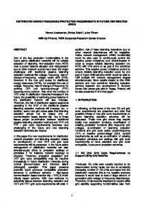
Figure 3. Generic DER system in IEC 61850-7-420 [13]
IV.
MODELING DER SYSTEMS WITH IEC 61850-7-420 EXTENSION
Soon after its publication IEC 61850 became very popular in power engineering circles as it addressed a vital aspect of communication lines in power systems. In an effort to encourage its utilization in microgrids which have more DG deployments, International Electrotechnical Commission formed Workgroup (WG17) to publish an extension of IEC 61850-7-4 Compatible logical node classes and data classes. This extension aimed at having logical nodes and data
classes that will help in modeling DER systems effectively. The overall system given in Figure 3 is used a template for modeling the DER systems given below; 1. 2. 3. 4.
Diesel Generators Solar panels (PV) Fuel Cells Combined Heat and Power
In addition to switching DERs on and off, DER systems involve:
•
Management of the interconnection between the DER units and the power systems they connect to, including local power systems, switches and circuit breakers, and protection.
•
Monitoring and controlling the DER units as producers of electrical energy
•
Monitoring and controlling the individual generators, excitation systems, and inverters/converters
•
Monitoring and controlling the energy conversion systems, such as reciprocating engines (e.g. diesel engines), fuel cells, photovoltaic systems, and combined heat and power systems
•
Monitoring and controlling the auxiliary systems, such as interval meters, fuel systems, and batteries
•
Monitoring the physical characteristics of equipment, such as temperature, pressure, heat, vibration, flow, emissions, and meteorological information
The system assumes a holistic sense in which the DER systems are modeled starting from their internal parameters such as fuel type for diesel generators, battery test results for Solar panels or hydrogen level for fuel cells to their grid connection types and parameters and to microgrid operator command and control units. Having detailed characteristics variables and measurement values entrenched inside, this modeling system serves for a rigorous communication system. In order to give a better insight about modeling DER systems with the mentioned publication, the new logical node classes and data classes shall be explained in four groups which are; DER unit controller, internal parameters, grid connection and network operator units. A. DER unit Controller The four LNs given at the top of Figure 3, under this heading DRCT, DRCS, DRCC and FSEQ comprises the DER unit controller logical device. These LNs are aimed at providing extensive information on the DER controller characteristics, its status and the supervisory control actions that can be undertaken. DRCT represents a controller which controls a single DER or a group of DERs connected to a single controller. Among other parameters it is required to input the number of DERs connected to it, types of these DERs and maximum output power values. DRCS provides information on the status of the controller such as its electrical connection, operation mode: automatic or manual, control mode: local or remote etc. By changing these parameters it is possible to control a DER’s electrical connection to the grid from a remote controller or, if it is required, only local and manual control might be enabled. In either case full representation of these data will be present in this logical node. DRCC represent the supervisory control on DER and it has a full list of actions that can be executed for desired
control. Setting different operating points, changing time delays, transient behavior, turning on and shutting down can all be performed thanks to this particular LN. Finally, LN FSEQ is required to provide information on the sequence of actions during starting up or shutting down of a DER. B. Internal Parameters These parameters indicate the internal status of the DG, the characteristics of the fuel (if any), storage systems, battery, exciter, generator unit, converter and the physical measurements to monitor the operation of the DG. Depending on the DER type, i.e. reciprocating engine, fuel cell, photovoltaic, combined heat and power; the energy converter logical node is selected from the new LNs provided such as, in proper order, DCIP; DFCL, DSTK and DFPM; DPVM, DPVA, DPVC and DTRC; DCHC, DCTS and DCHB. The reason for having more than one LN for the same DG type is to control and model different aspects of that particular DG. For example a fuel cell is modeled with DFCL which has fuel cell controller characteristics, DSTK which models the fuel cell stack and DFPM which represents the fuel processing module. Diesel generators, on the other hand, are modeled only with DCIP which includes all the ratings, measurements and control pertaining to the diesel generator. However, due to its structure the diesel generator requires an exciter modeled with DREX, DEXC and DSFC, and a generator unit modeled with DGEN, DRAT, DRAZ and DCST. In modeling fuel cells these components are out of question. Both of these DER systems require a fuel system modeled with MFUL and DFLV which represent fuel characteristics and fuel delivery systems. On the contrary, solar panels which depend on the solar energy do not require such modeling. The LNs given in Physical Measurements box in Figure 3 cover physical measurements including temperature by STMP, pressure by MPRS, heat by MHET, flow by MFLW, vibration by SVBR, emission by MENV, meteorological conditions by MMET. These measurements may belong to the fuel, generator, auxiliary systems for heating, cooling, lubrication; and environmental conditions that are crucial in ensuring safe and efficient operation. C. Grid Connection Units These LNs comprise the components which are required, or might be required depending on the DER type, for proper gird connection. DER circuit breakers and Utility Circuit breakers which are modeled with CSWI and XCBR are required for every DG connection. In a unique fashion, IEC 61850-7-420 proposed a logical node named XFUS is used to model a fuse and it can be likened to a circuit breaker for one-time use. The diesel generator requires the synchronizer RSYN so that its output is synchronized with the grid. As it is known, fuel cells and solar panels yield a DC output. A DC switch modeled with XSWI or CSWI is required to feed the output to
the converter. The converter converts the DC output of these generators to AC voltage and synchronizes the output in this process. Depending on the situation converters are modeled with ZRCT and ZINV. ZRCT is used in modeling rectifiers which converts generator output AC to intermediate DC. Properties can be set in detail such as types of commutation, isolation, voltage regulation, conversion (AC-DC, AC-AC-DC, AC-DC-DC), cooling method, AC system and filter types. Furthermore, current and voltage limits can also be set. ZINV is used in modeling inverters which converts DC input (either directly from a generator or intermediate DC fed by ZRCT) to AC. Properties can be set in detail such as switch type, cooling method, type of commutation, isolation, switching frequency and current connect mode. Furthermore, current and voltage limits can also be set. D. Network Operator Units These LNs are required to model Electrical Connection Point (ECP) logical devices and aimed at sorting out the issues related to Network operation such as legal information (ownership, authority, obligations and permissions), technical characteristics (types of DER devices, connection types, operation modes, ratings), control authority permissions and other management information. In brief at each ECP, DCRP includes DER plant corporate characteristics (such as ownership, contractual obligations and permission), DOPR has DER plant operational characteristics (such as DER device types, ratings, connection types, operation modes), DOPA has information on DER operational control authorities (who has the authority to switch on/off DGs or switches), DOPM is used to either get information about or set the operating mode of DGs, DPST represents the actual status at ECP including alarms and connection status, DCCT has the economic dispatch parameters, DSCC is used to control energy and ancillary services schedules and DSCH is the schedule for DER plant to provide energy and/or ancillary services. V.
FUTUREWORK
The authors currently conduct research on central microgrid protection systems which implement continuous communication between the components. They have already proposed some innovative protection system designs in their publications [14, 15]. The authors are currently modeling these protection systems according to the logical nodes and devices given in IEC 61850-7-420. Furthermore, as there is no fault current limiting device model in IEC 61850-7-420 the authors are planning to develop and propose such a structure. In this way this standard will cover larger aspects of microgrids. VI.
CONCLUSION
Microgrids have dynamic structures which change more often than the conventional large networks. Supplying power through alternative paths, new deployments and other factors hinder the selective operation in case of a fault. This requires
that a new method should be implemented which updates the operational parameters of microgrid components in parallel with the existing microgrid structure. In order to achieve this goal a centralized management is required to monitor and communicate with the microgrid components and assign suitable operation parameters which might be related to load sharing, stability, protection and generator control. The communication lines and systems inevitably utilized in microgrids require standardization so that equipments with different manufacturers or owners can work together, new deployments can be easily done. Design of a central microgrid management system will be very much simplified if all of the components use the same communication standard. Therefore, IEC 61850 and the extension IEC 61850-7-420 which is aimed at modeling DERs are published. When these standards are used by different manufacturers and owners, this will serve as a solid step for having plug and play concept in electrical networks. REFERENCES [1] C. M. Colson and M. H. Nehrir, "A review of challenges to real-time power management of microgrids," in Power & Energy Society General Meeting, 2009. PES '09. IEEE, 2009, pp. 1-8. [2] Kroposki B. et al, "Renewable Systems Interconnection - Executive Summary," Technical Report, National Renewable Energy Laboratory, NREL/TP-581-42292, February 2008. [3] R. A. F. Currie, et al., "Fundamental research challenges for active management of distribution networks with high levels of renewable generation," in Universities Power Engineering Conference, 2004. UPEC 2004. 39th International, 2004, pp. 1024-1028 vol. 2. [4] Boutsika T. et al., "Calculation of The Fault level contribution of Distributed Generation According to IEC Standard 60909," presented at the Proc. CIGRE Symposium Athens, April 2005. [5] T. S. Basso and R. DeBlasio, "IEEE 1547 series of standards: interconnection issues," Power Electronics, IEEE Transactions on, vol. 19, pp. 1159-1162, 2004. [6] J. Driesen, et al., "Protection Issues in Microgrids with Multiple Distributed Generation Units," in Power Conversion Conference Nagoya, 2007. PCC '07, 2007, pp. 646-653. [7] S. Conti, et al., "Analysis of protection issues in autonomous MV micro-grids," in Electricity Distribution - Part 1, 2009. CIRED 2009. 20th International Conference and Exhibition on, 2009, pp. 1-5. [8] N. Hatziargyriou, et al., "Microgrids," Power and Energy Magazine, IEEE, vol. 5, pp. 78-94, 2007. [9] P. R. Elkin, et al., "Substation automation and integration from relays to desktops," in 2nd Annu. Western Power Delivery Automation Conf., 2000, pp. 4-12. [10] A. Apostolov and B. Muschlitz, "Object modeling of measuring functions in IEC 61850 based IEDs," in Transmission and Distribution Conference and Exposition, 2003 IEEE PES, 2003, pp. 471-476 vol.2. [11] C. R. Ozansoy, et al., "The Application-View Model of the International Standard IEC 61850," Power Delivery, IEEE Transactions on, vol. 24, pp. 1132-1139, 2009. [12] C. R. Ozansoy, et al., "Object Modeling of Data and DataSets in the International Standard IEC 61850," Power Delivery, IEEE Transactions on, vol. 24, pp. 1140-1147, 2009. [13] I. T. WG17, "Introduction to IEC 61850-7-420: Distributed Energy Resources (DER) Object Modeling," White Paper, vol. Ver 2., July 31, 2009. [14] T. S. Ustun, et al., "A microgrid protection system with central protection unit and extensive communication," in Environment and Electrical Engineering (EEEIC), 2011 10th International Conference on, 2011, pp. 1-4. [15] T. S. Ustun, et al., "A central microgrid protection system for networks with fault current limiters," in Environment and Electrical Engineering (EEEIC), 2011 10th International Conference on, 2011, pp. 1-4.