(QoS) differentiation support. In this paper, we propose a fully distributed medium access control (MAC) adaptation method for service differentiation.
Distributed MAC Adaptation for WLAN QoS Differentiation Jun Zhao, Zihua Guo, Qian Zhang and Wenwu Zhu Microsoft Research, Asia 3F, Beijing Sigma Center, No. 49, Zhichun Road Haidian District, Beijing 100080, P. R. China {i-juzhao, zhguo, qianz, wwzhu}@microsoft.com Abstract— In current WLAN system that is designed for best-effort communications, there is not any quality of service (QoS) differentiation support. In this paper, we propose a fully distributed medium access control (MAC) adaptation method for service differentiation. It is implemented by dynamically updating the MAC layer parameters (such as contention window) to adapt to the network conditions in a class-based fashion. In this sense, the QoS classes are differentiated and the system performance is significantly improved in terms of delay, packet loss and throughput while ensuring fairness and stability. The key idea of our scheme is the introduction of a mapping function and a target contention window. It is demonstrated that our proposed adaptive MAC can outperform both the basic 802.11 MAC and the fixed differentiation scheme with very low complexity.
can be adjusted in a class-based fashion. Then, the service differentiation will be achieved and the QoS performance will be greatly improved. There has been some related research work in literature on MAC QoS differentiation. In [4], based on a case-bycase study, the authors proposed some fixed differentiation schemes. In this scheme, the high priority user will obtain better QoS than the low priority user. However, since the CW is fixed irrespective of the network conditions, the disadvantage of the fixed scheme is obvious: •
I. I NTRODUCTION The WLAN system is now getting more and more popular due to the low cost and high capacity, etc. However, current WLAN systems, such as IEEE 802.11a/b, are designed to support the best-effort data communications and there is not any QoS support. That is, in distributed coordination function (DCF) mode of 802.11, the parameters are set to be identical for all traffics. In particular, the initial contention window (CWmin) for IEEE 802.11b is set to be 31 for each flow (in the following, if not specifically mentioned, CW denotes CWmin). In addition, QoS inter-frame space (QIFS) is equally set to be distributed IFS (DIFS) for all users. As a result, each user is treated identically and no service differentiation available. Thus, the performance of the multimedia traffics with various QoS requirements will not be satisfactory in current WLAN system based on 802.11 DCF. Investigation the impacts of MAC parameters (CW, IFS) is important to improve DCF performance. There has been much work on this topic. Bianchi and Cali et al. derived the analytical model of DCF for throughput analysis [8][9][10]. However, their work did not consider MAC level differentiation. To support QoS differentiation, we should assign different MAC parameters (CW, IFS) to different QoS classes. But the problem is how to assign these values. We have done lots of work on performance analysis of differentiated DCF [1][2]. However, these methods need much global information of the network (user number, user traffic, and etc.), which is difficult to get in a distributed environment. Therefore, in this paper, we propose a distributed method for parameter adaptation, which also provides MAC level service differentiation. It is an adaptive scheme that can run in a per-user or per-flow fashion to adjust user’s MAC layer parameters dynamically. Each user observes the local information and based on it, the CW, QIFS
•
When the system contains several users, the collision probability will be rather large (we have found that it will be larger than 30% when busy). In this case, the fixed CW value will be too small and all the users try to transmit within such a small window although with backoff. Thus, the collision will waste a lot of spectrum efficiency. On the other hand, when the WLAN system contains only a few users, and the collision probability is quite small. In this case, the fixed CW value may be unnecessarily too large since the user needn’t wait so long time to transmit a frame.
From above discussion, we can see that the fixed differentiation scheme cannot achieve a satisfactory spectrum efficiency and QoS. Other work related to the service differentiation in WLAN includes [5][6]. The work in [5] designed a new protocol for differentiation and to resolve contention. It actually required a modification of the basic 802.11 MAC. In [6], a virtual MAC on the 802.11 MAC was proposed. It was very complicated due to the heavy computation load. Although the two basic observations listed above for MAC configuration are quite intuitive, the distributed adaptive adjustment is very difficult because we need to guarantee the system stability and user fairness within the same class. •
•
In the distributed scheme, each user only knows his/her own information and makes adjustments based on the local observed data. However, the observed transient local information may be quite different due to the variance even for the users within the same class. Thus, how to assure the users within the same class yield a similar CW? So far, no work was reported in this area. Furthermore, in the simulations, we have found the positive feedback in the MAC layer. For example, when a user sees many collisions and increases the CW while other
users has not done so, he/she will see more collisions, which will incur a further increase of CW, and vice versa. This will cause the system instability and user unfairness. The rest of the paper is organized as follows. In Section II, we present our adaptive adjustment scheme in detail. In Section III, simulation results are given to demonstrate the potential of our proposed scheme. Finally, the conclusions are drawn in Section IV. II. D ISTRIBUTED A DAPTATION In this paper, we only focus on the adaptive adjustment of CW. Our work is based on the available information retrieved from the standard network card interface, say, the NDIS [7]. In our scheme, the network monitor queries the interface every T seconds and obtain some statistics in the previous T seconds, such as total transmitted frames (TransmittedFragmentCount), the total failed transmissions without receiving ACK frame (ACKFailureCount), the total successful transmissions with one or more than one retransmissions (RetryCount) [3][7], etc. Based on these values, we can calculate our defined metrics, such as the collision probability, failure probability, etc. After properly smoothing these metrics, we can use them as the guideline to update the MAC parameters for this user. The metrics used in our scheme are properly defined so that they can reflect not only this user’s status but also the system status. A. Adaptation Adjustment 1) Metrics: Failure probability Pf . This indicates that among the total trials to transmit packets, how many trials fail due to collision. When RTS/CTS is used, the probability of failure is defined as: RT SF ailureCount . Pf = RT SF ailureCount + RT SSuccessCount Otherwise, it is defined as:
•
CWminu
CWminu
CWtarget
f f CWminl
CWminl Pfl
Pfu
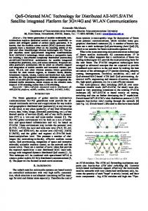
(a) Mapping function Fig. 1.
Pfl
Pf,equ Pfu
(b) Convergence to target CW
Mapping function and target CW
1 Every T second, check how many transmissions are tried (count from previous adjustment), if smaller than 100, go back to Step 1. 2 Calculate Pc , Pf and smooth it. Pc (n) = αPc (n − 1) + (1 − α)Pc,measured (n) Pf (n) = αPf (n − 1) + (1 − α)Pf,measured (n), where α is the smoothing factor; while Pc,measured and Pf,measured are calculated in current interval. 3 If previous ∆CW > 0 and Pc (n) > Pc (n − 1) or Pf (n) > Pf (n − 1), go to Step 1; else, continue. If previous ∆CW < 0 and Pc (n) < Pc (n − 1) or Pf (n) < Pf (n − 1), go to Step 1; else, continue. 4 Calculate ∆CW with (1) and update CW. ∆CW = S
CWtarget − CWcurrent , CWcurrent
(1)
where S is the scaling factor and different for various QoS class. CWtarget is the target CW value obtained from a mapping function, which is described in the following; while CWcurrent is the current CW value. Here, Step 1 ensures that we have enough data for statistics. Pf = Step 2 is to smooth the observed information to reduce ACKF ailureCount . variance. While the main policies, Step 3 and Step 4 will be T ransmittedF ragmentCount + ACKF ailureCount explained in detail as follows. • Collision probability Pc . This probability indicates among the total transmitted frames, how many frames are trans- B. Target CW and Mapping Function mitted successfully with more than one try. It has the As we mentioned in previous section, the basic observation similar meaning as Pf and is more generally defined as of configuring the CW is: small Pc or Pf corresponds small retry count divided by total transmitted fragment count: CW and large Pc or Pf corresponds large CW. Thus, we can design a one-to-one mapping of Pc or Pf to a target RetryCount . Pc = CW size, which is shown in Fig. 1(a). The Pf l is the failure T ransmittedF ragmentCount probability corresponding to a target CW=CWminl .1 When 2) Adaptation Algorithm: Our MAC adaptation scheme the failure probability is below Pf l , the target CW is still set aims to fairly and efficiently share channel resources. It updates to be CWminl . Similarly, Pf u is the failure probability corthe CW to achieve tradeoff between two points: the idle responding to a target CW = CWminu . When the estimated period wasted on waiting backoff counter reducing to zero failure probability is above Pf u , the target CW is still set and the collision period plus backoff due to simultaneous to be CWminu . With tremendous simulations under various transmissions of more than one stations. Here, we assume a scenarios, we have found that when the user number is large, clean WLAN channel and collision is the only reason for transmission failure. Our distributed MAC adaptation algorithm is 1 CW minl and CWminu is our predefined lower bound and upper bound of the CWmin . actually very simple and described as follows:
C. Differentiation The differentiation between different QoS classes is achieved by setting different parameters for various QoS classes. The scaling factor can be divided into up scale and down scale, which are used for increasing and decreasing CW, respectively. For QoS classes with higher priority, the up scale is set to be smaller than that of lower priority; while the down scale is set to be greater than that of lower priority. The differentiation method is also supported by the mapping function. The mapping function can be any monotonically increasing function that passes through two points,
Mean Delay (ms)
1200 802.11, overflow 1000 800 600 400
0
5
Mean Delay (ms)
10
15
User ID
100
Fixed scheme Adaptive MAC
80 60 40 20 0
0
5
10
15
User ID
(a) Mean latency(real time flow) 4 3.9 3.8 3.7 Godoput(Mb/s)
both Pc and Pf can be larger than 30%. On the other hand, when the user number is small, Pc and Pf are usually smaller than 2%. Therefore, in our scheme, we set Pf l = 2% and Pf u = 30%. The target CW is not the size that each station will tune its CW to be. It is only used to guide the direction of CW adjustment. The actual step size is determined by both the target CW and the current CW, which is given in (1). This feature means that even two stations estimate the channel with the same status, the actual step sizes may still be different. The key idea of our scheme is the introduction of mapping function and target CW. Several features guarantee the user fairness and system stability. • Although the transient Pc and Pf observed by the users within the same class will be different (as large as 15%) due to the variance, the difference in CW is kept in a reasonable threshold since they are absorbed in the expression of (1). This is vital to assure user fairness. • The adjustment step size is adaptive. The larger the difference between CWcurrent and CWtarget is, the larger the step size will be, and vice versa. This assures the small fluctuation of steady-state CW around the target CW. The convergence procedure is illustrated in Fig. 1(b). Initially, CW may be rather small and Pf is rather large. The user deems that CWtarget should be, say, as large as CWminu . With (1), the CW is increased and then, the observed Pf is decreased a little and the user deems that CW should be another CWtarget that is smaller than previous one and CW is increased further... Finally, the CW will be increased to CWcurrent by seeing a Pf that is exactly corresponding to CWcurrent . In this case, CWcurrent = CWtarget , which is equilibrium. • Another policy to assure fairness and stability is a mechanism called stop-for-a-round, which is Step 3 in our scheme mentioned before. The station that increases CW size should statistically see decreased Pc and Pf if all other stations in the same class also do so. However, if in next round, the user actually sees increased Pc or Pf , this indicates that the other users haven’t increased their CW and only he/she is the victim. In this case, this user should hold the CW in this round and leave time for others to adjust the CW. Similar actions will be taken when decreasing CW. As a result, the fairness can be maintained statistically.
3.6 3.5 3.4 3.3
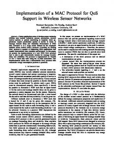
Adaptation, Goodput=3.82Mb/s Fixed, CW=(31,63), Goodput=3.67Mb/s 802.11, CW=(31,31), Goodput=3.45Mb/s
3.2 3.1 3
10
20
30
40 50 Time(sec)
60
70
80
(b) Total system throughput Fig. 2.
Comparison of three schemes
(Pf l , CWminl ) and (Pf u , CWminu ). One of the simplest choices is the linear function. For higher priority flows, the CWminl and CWminu can be set to be smaller than those of lower priority flows. Here we give a two-class example, which includes the real-time traffic and the best-effort traffic. For real-time traffic: CWminl = 15, CWminu = 63, and Pf l = 2%, Pf u = 30%. For best-effort traffic: CWminl = 31, CWminu = 127, and Pf l = 2%, Pf u = 30%. Actually, we have found that these parameters work well in almost all simulated cases. So, these set of parameters are used in the following simulations. III. S IMULATION R ESULTS To show the potential of our proposed adaptive MAC for QoS differentiation and improvement, we demonstrate some typical simulation results here. In this section, for simplicity, we assume only two QoS classes: real-time and best-effort data. But more classes can be managed in a similar manner. The real-time flow is CBR traffic, while the best-effort flow is assumed to always have data to send. We compare the proposed approach with other two schemes, namely, the fixed differentiation scheme and 802.11 legacy scheme. In the fixed scheme, the CW values for the two classes are fixed to be 31 and 63, respectively. In 802.11 scheme, the CW is fixed to be 31 for all users. For comparison, in our adaptive scheme,
80
60
40
Real time flow
20
0
Best effort flow
0
1000
2000
3000 4000 Delay (ms)
5000
80 Real time flow 60
40 Best effort flow 20
0
6000
100 Cummulative % of packets
100 Cummulative % of packets
Cummulative % of packets
100
0
1000
(a) 802.11
2000 Delay (ms)
3000
60
40 Best effort flow 20
0
4000
0
500
(b) Fixed differentiation Fig. 4.
1500 2000 Delay (ms)
2500
3000
Differentiation ability
1−80s, 20x100Kb
0.4 FLR
Real time flow Best effort flow
140
1000
(c) Our adaptive MAC
160
120
802.11b Fixed Adaptive
0.2
100
0
80 60
5
10 User ID
15
81−160s, 10x100Kb+ 9x200Kb
40 20
2
4
6
8 User ID
10
12
14
0
140
0
2
4
6
8
10 User ID
12
14
FLR
Real time flow Best effort flow
100
0.02
80
0
16
18
802.11b Fixed Adaptive
0.04
120
20 802.11b Fixed Adaptive
0.05
(a) Final CW value Contention Window
0
0.1 FLR
Final Contention Window
Real time flow
80
161−240s, 1 x100Kb+2x1.4Mb 1
2 User ID
60
3
40 20
Fig. 5. 0
10
20
30
40 50 Time (second)
60
70
(b) Convergence of CW Fig. 3.
FLR comparison
80
Fairness and convergence
the initial CWs for two classes are set to be 31 and 63, respectively. In the simulations, the parameters of our scheme are configured as follows: • α = 0.3, T = 1 second. • Real-time traffic: Sup = 20, Sdown = 20. • Best-effort traffic: Sup = 40, Sdown = 10. • CWminl and CWminu are listed in Section II. • The mapping function is the simplest linear function. A. Stationary Traffic First, we simulated an 802.11b network with packet size=500 bytes and RTS is not used. The system consists of 15 users running real-time flows with average bit rate=128kbps and 15 users running best-effort flows. They are all communicating through AP. In Fig. 2, the delay of the real-time flows and the total system throughput are shown. We can see that in this case, the real time flow in the basic 802.11 scheme actually breaks down. The delay is around 1 second. However, the fixed differentiation and our adaptive scheme can work well. Furthermore, the delay of adaptive scheme is only half of that of the fixed scheme. At the same time, the total
system throughput of our adaptive scheme is the largest. From these, we can see that the adaptive scheme can significantly reduce the delay of the real-time flows. That is, the services are differentiated. In addition, the channel utilization is improved compared with other two schemes. This is due to the reduction of collisions by adaptively increasing the CW. This indicates that the adaptive MAC can not only greatly improve real-time flow QoS but also improve the best-effort flow’s throughput due to the increased total system throughput. It should be noted that in Fig. 2(a), the mean latency values of the real-time users are very similar, which indicates the fairness among the users of the same QoS class. To further demonstrate the fairness, in Fig. 3(a), the steady-state CW of both the real-time users and best-effort users are shown. We can see that, within each class, they are almost the same. Fig. 3(b) shows the convergence speed of the adaptive scheme. We can see that the real-time flow converges around 10 seconds; while the best-effort flow converges around 20 seconds. However, the convergence speed can be faster if the query time reduces, say, to 500 ms. In Fig. 4, we present the latency distribution (Cumulative Distributed Function) of the two classes of flows, which shows the differentiation ability of three schemes. We can see that the 802.11b system cannot differentiate the two classes at all. For the fixed differentiation, the two classes are differentiated. But the two groups of curves scatter somehow. In our distributed
3
60 Mean Delay (ms)
2.95 2.9
2.8 2.75
40
20
0
0
5
Adaptive MAC Fixed differentiation 802.11 MAC
2.65
15
(a) Delay comparison of different mapping functions
2.6
4
2.55
3.9
2.5
10 User ID
2.7
0
50
Fig. 6.
100 150 Time(sec)
200
Goodput comparison
Godoput(Mb/s)
Godoput(Mb/s)
2.85
Linear Function Exponential Function Polynomial Function
3.8 3.7
3.5
adaptive MAC, the two classes are differentiated and the curves are grouped quite well. This indicates again that the users within the same class are quite fair. B. Dynamic Traffic In Fig. 5 and Fig. 6, we present a join-and-leave scenario with packet size = 500 byte and RTS is used. Each stage is simulated for 80 seconds: 20 best-effort flows+20 real-time flows (100 kbps each)→10 real-time flows (100 kbps each) + 9 real-time flows (200 kbps each)→1 real-time flows (100 kbps) +2 real-time flows (1.4 Mbps). In Fig. 5, the frame loss rate (FLR) is shown. We can see that in the first stage, the adaptive scheme and the fixed differentiation scheme achieve much better FLR than the 802.11 scheme. In the second and third stages, our adaptive scheme can achieve a performance of FLR nearly 0 and the other two schemes all yield an FLR=5%. Again, the throughput of the adaptive MAC is the largest, which is shown in Fig. 6. From above results, we can conclude as follows: • Our proposed adaptive scheme can adjust the CW according to the network condition. Thus, it can achieve better channel utilization than both the fixed scheme and the 802.11 scheme. In all cases, we found that it yields the largest total system throughput. • It differentiates the QoS classes efficiently. In particular, the QoS performance of the real-time flow is significantly improved in either latency or FLR. At the same time, the best effort flow also obtains some gain since its throughput is improved. C. Effect of Mapping Function As we mentioned before, the key of our scheme is the introduction of the mapping function and the target CW. In Fig. 7, we show the performance with three different mapping functions. They are the simplest linear function, exponential function and polynomial function. The system is configured similarly as in Section III-A except the mapping function. We can see that the delay and throughput are quite similar for these three mapping functions. Therefore, we can see that the system performance is insensitive to the shape of the mapping function.
Linear, Goodput=3.81Mb/s Exponential, Goodput=3.82Mb/s Polynomial, Goodput=3.82Mb/s
3.6 10
20
30
40 50 Time(sec)
60
70
80
(b) Goodput comparison of different mapping functions Fig. 7.
Comparions of different mapping functinos
IV. C ONCLUSIONS In this paper, we proposed a fully distributed MAC adaptation method in IEEE 802.11 WLAN for QoS differentiation. It adjusts the CW according to the network condition adaptively. The key idea of our scheme is the introduction of the target CW and mapping function. We have shown the advantages of our proposed adaptive MAC over current 802.11 MAC and the fixed differentiation scheme. The main features of our adaptive scheme are as follows: • It is distributed and very simple. • It can achieve better QoS than the other two schemes. • It can differentiate services efficiently. • It guarantees system stability and user fairness. • The choice of mapping function is very flexible. R EFERENCES [1] J. Zhao, Q. Zhang, Z. Guo, and W. Zhu, “Throughput and QoS Optimization in IEEE 802.11 WLAN,” in Proc. 3GWireless 2002, May 2002. [2] J. Zhao, Z. Guo, Q. Zhang and W. Zhu, “Performance study of MAC for IEEE 802.11 WLAN,” in Proc. IEEE Globecom’02, Nov. 2002. [3] IEEE standard for wireless LAN-medium access control and physical layer specification, part 11, IEEE Press, New York, NY, 1999. [4] A. Banchs, X. Perez, M. Radimirsch, and H. Stuttgen, “Service Differentiation Extensions for Elastic and Real-time Traffic in 802.11 Wireless LAN,” in Proc. IEEE Workshop on High Performance Switching and Routing, 2001. [5] I. Aad and C. Castelluccia, “Differentiation Mechanism for IEEE 802.11,” in Proc. IEEE Infocom’2001, pp. 209-218, Apr. 2001. [6] A. Veres, A. Campbell, M. Barry, and L. Sun, “Supporting Service Differentiation in Wireless Packet Networks Using Distributed Control,” in IEEE J. Select. Areas Commun., pp. 2081-2093, Vol. 19, No. 10, 2001. [7] Microsoft Corporation, Network driver interface specification (NDIS) 5.0. [8] G. Bianchi, “Performance analysis of the IEEE 802.11 distributed coordination function,” in IEEE J. Select. Areas Commun., pp. 535-547, vol. 18, no. 3, 2000. [9] F. Cali, M. Conti, and E. Gregori, “Dynamic tuning of the IEEE 802.11 protocol to achieve a theoretical throughput limit,” in IEEE/ACM Trans. Network., pp. 785-799, vol. 8, no. 6, 2000. [10] F. Cali, M. Conti, and E. Gregori, “IEEE 802.11 protocol: Design and performance evaluation of an adaptive backoff mechanism,” in IEEE J Select. Areas Commun., pp. 1774-1786, vol. 18, no. 9, 2000.