QoS-aware resource management, and the application-aware service management as shown in Figure 1. Application-to-Component Translation. QoS Proxy.
Distributed QoS Compilation and Runtime Instantiation 1 Klara Nahrstedt, Duangdao Wichadakul, Dongyan Xu Department of Computer Science University of Illinois at Urbana-Champaign Urbana, IL 61801
Abstract The rapid growth and coexistence of different application domains, such as multimedia and electronic commerce, present a significant challenge to the provision of their Quality of Service (QoS). To solve this challenge, we need a unified QoS framework, which allows flexibility and reconfigurability. In this paper, we present a reconfigurable ���� component-based QoS framework, called , which solves the challenge by partitioning the end-to-end QoS setup process into distributed QoS compilation and runtime QoS instantiation phases for different types of applications. Entities, services and protocols of this framework, such as application-to-component translator and component-to-resources translators, achieve the distributed QoS compilation and prepare all necessary QoS structures for the end-to-end QoS setup. Other capabilities of this framework, such as a reconfigurable middleware and functional adaptation, achieve the runtime instantiation of the end-to-end QoS setup. We have implemented the first prototype of this framework and the results show a feasible overhead of the runtime service instantiation and reconfiguration for different applications and their QoS requirements.
I. I NTRODUCTION The rapid growth and coexistence of different application domains, such as multimedia and electronic commerce, present a significant challenge to provision different levels of QoS. The big question is: “How should a unified end-system QoS framework look like to allow different applications to use it and achieve required QoS guarantees without re-implementation of the underlying QoS services.” Current QoS frameworks are tailored towards specific 1
This work was supported by the National Science Foundation under contract number 9870736, the Air Force Grant under contract number F30602-97-2-0121, National Science Foundation Career Grant under contract number NSF CCR 96-23867, NSF PACI grant under contract number NSF PACI 1 1 13006, NSF CISE Infrastructure grant under contract number NSF EIA 99-72884, NSF CISE Infrastructure grant under contract number NSF CDA 96-24396, and NASA grant under contract number NASA NAG 21250.
applications such as providing QoS guarantees for multimedia services [1, 2, 3, 4, 5] with timing and bandwidth requirements, or for messaging services [6, 7] with reliability requirements. Hence, there is currently no unifying framework which would allow a clear QoS specification, translation, and configuration of a QoS framework for different applications. Furthermore, the QoS frameworks lack a clean methodology of how to specify QoS, how to compile QoS parameters for different applications, how to configure and instantiate corresponding end-to-end QoS path during the runtime, as well as how to reconfigure services in a distributed fashion when resources become scarce. The current QoS frameworks have services such as QoS monitoring and QoS adaptation, however, these services are tied to resource management and data adaptation. In this paper we present a unified QoS framework, called ���� , and a methodology of an establishment process from user QoS specification through QoS compilation to runtime end-to-end execution of end-system services configured according to the user QoS specification. Our QoS framework differentiates itself from existing QoS frameworks by (1) introducing a distributed QoS translation and compilation process to prepare QoS structures and mappings for runtime QoS setup; (2) providing dynamic discovery and configuration protocols to synchronize services and resources when establishing end-to-end QoS during the runtime, and (3) expanding the data QoS monitoring and data QoS adaptation towards functional configuration and reconfiguration of services for provision of QoS guarantees. Our solution takes a component-based middleware approach and consists of two phases: (1) distributed QoS compilation phase which is performed in the off-line mode of a considered application, and (2) runtime instantiation phase during which the application end-to-end services as well as the QoS-aware middleware services are dynamically configured and set up according to user QoS specification. In Section 2, we outline the overall framework architecture as well as entities participating in this framework. Section 3 expands in detail on the distributed QoS compilation phase, the algorithms, services and protocols achieving the desired end-to-end QoS translation. Section 4 discusses the configuration and instantiation of end-to-end services
according to the user QoS specification during the runtime phase. In Section 5, a running example presents the usability of the QoS framework by describing concrete structures, services and protocols in both phases. In Section 6, we present the implementation, based on dynamic TAO [8] and component-based 2K system [9], and experiments with our first prototype of this unified QoS framework. In the Section 7, related work is briefly discussed. We conclude in section 8 with lessons learned from this framework.
The runtime instantiation phase is performed online and it has two major goals: (1) QoS setup of an end-to-end QoS path according to given user QoS requirements as well as negotiation of a QoS contract between the user and the underlying system and network; (2) functional QoS adaptation and dynamic service reconfiguration during the runtime.
II. ���� F RAMEWORK
III. D ISTRIBUTED Q O S C OMPILATION P HASE
The unified QoS framework is a component-based, multi-tier middleware framework which consists of the QoS-aware resource management, and the application-aware service management as shown in Figure 1. Application-to-Component Translation
QoS Proxy
Service Configuration QoSProxy Entity Adaptation
Application-Aware Service Management
Distributed Resource Coordination Entity Resource Broker Data Adaptation
Resource Broker Data Adaptation
QoS-Aware Resource Management
Figure 1: Reconfigurable Component-based QoS Framework ( ��� � )
The QoS-aware resource management is based on the concept of resource brokers which have the capabilities of the QoS-aware resource admission, reservation, allocation, � � enforcement and data adaptation. The QoS-aware resource management relies on the QualMan system [10] which delivers the above capabilities for CPU, memory and network resources. The application-aware service management uses the QoS proxy to provide capabilities such as component configuration, component adaptation, translation between an application and underlying service components, as well as translations between QoS of components and the required underlying resources. This paper concentrates mainly on �� � the application-aware service management part of the framework because the QoS-aware resource management ���� is already published in [10, 11]. The framework establishes the QoS contract in two phases: (1) distributed QoS compilation phase and (2) runtime instantiation phase. The distributed QoS compilation phase is performed off-line and it prepares QoS parameters and structures for a specific application. The goal of this phase is to take an application, represented by a functional graph, and its user QoS requirements, and translate it into application and system QoS parameters. During the runtime, the application then takes these parameters to get a QoS contract from
the underlying system and networks or to adapt its QoS contract.
The distributed QoS compilation phase deals with QoS translations in multi-facet way. The translations range from analytical translations to measurement-based translations between different QoS parameters. This phase runs before a user requests an application with a QoS contract. The reason we need this phase is because different applications might require different QoS translations, structures and parameters. Hence, we need to examine (sometimes even instrument) the application and find out the QoS relations so that when the application enters the runtime phase with the goal to achieve a QoS contract, the end-to-end QoS instantiation can be done efficiently. This is similar to the language compilation concept where an application source code is optimized and translated into an executable code by the language compiler, so that during the runtime we get a highly optimized and high-performance program. The distributed QoS compilation phase requires four major specifications done by the application designer in order to perform the compilation process: (1) Specification of an application via a functional graph which presents feasible configurations of service components2 and the interactions among them; (2) Specification of relations between user QoS parameters, given by the user of an application, and the corresponding application QoS parameters, represented via an application-specific translator (TApp); (3) Specification of relations among the application code, its services, and possible locations of services (service component description), and (4) Specification of application-specific adaptation policies and other application-related information such as importance. Once these specifications are in place, the QoS compilation protocol executes as follows:
First Step: The specification of the application via the functional graph is translated into a set of component configurations, dependent on multiple paths, specified by the functional graph. 2 We decompose an application into a set of services and each service will be represented and implemented by a component. Hence, in the text the two terms ’service’ and ’component’ are interchange-able.
Second Step: The set of component configurations (result of the first step) together with (a) the specification of relations between user QoS requirements and application QoS parameters inside of the application-specific translator, (b) the specification of relations between application code, components and location, and (c) the specification of application-specific adaptation policies and application-related information, are translated into the QoS-aware component specification (QoSCSpec). This translation is performed by the application-to-component translator as shown in the Figure 2. Service component description
Adaptation policies
Application-specific Translators TApp
Application functional graphs
Application-to-Component Translator
SC’s QoS
TApp TApp
QoS-aware Component Specification (QoSCSpec) TApp: Application-specific translator
Figure 2: Application to Components QoS-aware Translator
In this step, the QoSCSpec consists of the following information: (1) application information such as name and request priority, (2) adaptation policies such as dropping policies for transport components, (3) dependencies among components, expressed via QoS-based configurations, and (4) per component QoS specifications, including the locations of the components within the considered platform. Note that the result of this step is a set of component configurations, labeled with corresponding application QoS, and possible locations of components. Figure 3 shows the QoSCSpec structure. QoS-aware component specification (QoSCSpec)
Application Adaptation Configurations Information Policies Name Request priority
Service component QoS spec. Service-specific QoS specs. Component name Machine platform List of required resources QoS attributes QoS attributes preference spec.
Figure 3: QoS-aware Component Specification (QoSCSpec)
Third Step:
This is achieved either by analytical translations if any exist or by the probing service, performing measurement-based translations. Analytical translations provide translations between application QoS parameters and the network QoS parameters3 . For example, we can translate user frame rate and frame size parameters into a required network bandwidth [12]. The probing service runs the application’s possible QoS configurations in a lightly loaded environment and measures the amount of required resources for each service component. The result is stored in the field ‘Service Component QoS Specification’ of the QoSCSpec structure.
The QoS-based configurations in QoSCSpec must be translated into the corresponding system QoS parameters and their resource requirements (e.g., CPU or network bandwidth).
The result of the overall QoS compilation phase is the QoS-aware component specification structure (QoSCSpec), including all the QoS-aware configurations and their corresponding resource requirements. The dynamic downloading and distributed probing are the underlying mechanisms for resource profiling in the compilation phase. QoSCSpec for an application can be stored at the initiator site (e.g., client) and/or initiatee site (e.g., server) and/or intermediate sites. For example, if we have a powerful client (e.g., workstation), then the QoSCSpec structure can be stored at the client site. On the other hand if the client is a thin client (e.g., palm pilot ), then the QoS structure could be stored at a specific server, such as the discovery server or the server of the corresponding application, or it can be distributed.
IV. RUNTIME I NSTANTIATION P HASE The runtime instantiation phase needs to provide (1) a QoS setup protocol for the application’s setup of end-to-end QoS guarantees according to specified user QoS parameters, and (2) adaptation services during the runtime of applications in case of changed resource availability. The QoS setup takes first a user request (e.g. a service description with required QoS parameters), and based on the information, it looks up in the QoSCSpec structure what are the corresponding component configurations and their QoS/resource requirements. Several configuration paths can be result of this look-up step. With this result, the QoS setup enters the service configuration discovery protocol. Once the appropriate configuration path is found, resource reservation and allocation protocol can be executed in an end-to-end fashion [10]. Note that a configuration discovery protocol can be executed in multiple ways. For example, the protocol can pick one configuration out of the set of possible configurations satisfying given user QoS, and the 3 Network QoS parameters are subset of the system QoS parameters.
components are then down-loaded and configured at individual nodes along the end-to-end path. Another possibility is to use a discover server where the configurations in QoSCSpec are stored, and the most appropriate configuration path can be found locally on this server. Once a configuration path is found, the individual components are down-loaded to individual nodes and configured accordingly. This solution is a centralized solution. There exists also a distributed solution which requires that the sender has all corresponding configurations available, and the sender sends a request over multiple configuration paths to down-load, configure individual components on the path nodes, and to collect information about the end-to-end performance of individual configurations. The receiver chooses the best configuration.
Discovery Server Component Repository
QoSCSpec Discovery Service 4
1 2
4
Initiating node
Distributed node
SC TCom
3 6
...
SC 5
Resource Broker
...
TCom
5
5
Resource Broker
Resource Broker
5
Resource Broker
3 6 Distributed node SC
...
TCom
The distributed solution delivers a configuration path which is closest to the given QoS request because the discovery will be based on the most recent resource availability information. However, this approach also requires a lot of overhead as multiple configuration paths might need to be pursued and a lot of resources blocked before a final decision for an application is met. The single configuration path selection is the fastest and lowest overhead approach, however, it is also the most inaccurate solution to the configuration path problem. Therefore, we selected at this time the discovery server approach which we describe below.
A. Service Configuration Discovery Protocol The configuration discovery protocol finds the best possible configuration path and allocates individual service components among distributed nodes such that each component will have sufficient available resources to satisfy requested QoS. To achieve this goal, each node includes a service configuration entity and the distributed configuration protocol enforces the interactions among the service configuration entities shown in Figure 4. Our configuration protocol performs the following steps: First, prerequisite or alternative components and the corresponding QoS component-to-resources translators (TCom) of the initiating node are found in the QoSCSpec and dynamically down-loaded according to the current available resources. Second, on behalf of the requested application, a query is issued to the discovery server for available required service components (SC) on distributed nodes. Third, the discovery service inside the discovery server proposes suitable configuration path node(s) as the result of a query to the initiating node. The initiating node contacts the proposed node(s), passes the corresponding dependency graph, and waits for the notification of success or failure. Forth, a distributed node determines if the required components are already in the node or not. If the
SC : Service Component TCom : Component-to-Resources Translator
5
Resource Broker
5
Resource Broker
Figure 4: Service Configuration Discovery Protocol
required components are not in the node, the node contacts the component repository to dynamically down-load the components. Fifth, the node contacts the local resource brokers asking the current available resources. During this step, the component-to-resource translation is active. This translation utilizes the compiled information about the relations between components and resources, stored in QoSCSpec, as well as online resource usage monitoring and translation. If a resource is insufficient (e.g. a resource utilization is over a threshold), reconfiguration needs to occur. Sixth, the result of the component allocation on a distributed node is sent back to the initiating node. The complexity of the service configuration protocol depends on application domains which require different components running on various locations in the distributed environment. For example, to provide QoS for the Messaging Service, the service configuration engine has to locate the appropriate locations of messaging routers which forward a message to another router and synchronously deliver a message to their intended target [13]. On the other hand, for a distributed omni-directional visual tracking system [14], the service configuration discovery has to locate an appropriate gateway to control switching capabilities from one camera server to another according to client’s request. The messaging routers and the omni-directional gateways are examples of configuration path nodes with corresponding service components. Note, that after the configuration discovery protocol, the end-to-end resource reservation and allocation protocol executes4 , using various resource brokers as described in 4
Our QoS framework performs in an heterogeneous environment, hence some nodes such as thin clients might
Discovery Server
[10].
Component Repository
B. Integrated Adaptation Model Adaptations are necessary in our framework due to the following two reasons: First, the resource reservation uses an optimistic approach for resource reservation which means that resources are reserved only for minimum QoS guarantees. If the reserved resources cannot satisfy the required bursts during the execution time, adaptations have to take place. Second, our QoS framework was designed for heterogeneous environments where nodes can have different types and levels of resource availability and usage. For example, for some nodes, a resource reservation does not make sense, hence in order to provide application QoS, we will deploy adaptation services in the middleware to adjust the resource allocation in case of availability changes. The adaptation model consists of an integration of data, and functional adaptation capabilities, assuming adaptive and reconfigurable applications. Data adaptation is a resource-level adaptation which is resource-specific. An amount of a reserved resource can be dynamically adjusted based on data-specific adaptation strategies (e.g. drop of packets, skip a CPU cycle) provided by a resource broker. If a low-level adaptation cannot reconcile QoS violation, functional adaptation will take place for component reconfiguration [14]. Functional adaptation(QoS Proxy adaptation) is the component-level adaptation which deals with component reconfigurations. This adaptation service is part of the Service Configuration Entity as shown in Figure 1. The cause for a new configuration path can be a component allocation failure, component-resource reservation or allocation failure, QoS degradation, QoS upgrade, and QoS violation.
QoSCSpec Discovery Service
Service Configuration QoSProxy Entity Adaptation
Resource Broker Data
not need reservation for all resources as they do not share some resource (e.g., CPU on the palm pilot). Our end-to-end resource allocation protocol takes this into account.
Adaptation
Figure 5: Integrated Adaptation
invocation path for intercepting message invocations or switching from a router proxy to another router proxy are examples of the middleware reconfiguration. Figure 5 shows the integrated adaptation model.
V. E XAMPLE OF Q O S C OMPILATION AND RUNTIME I NSTANTIATION A. Distributed QoS Compilation Phase
� � In the framework, an application developer is responsible to specify the following information:
Application
functional graph represents dependencies among possible combinations of components to form an application. Figure 6 shows an example of a Video-on-Demand (VoD) application functional graph with three service components ���� (Retrieval Service), ���� (Display Service), and ���� (Transcoding Service). The visual graph is then internally translated into two configuration paths [( �� �� ���� ), ( �� � ������ ���� )] as shown in Figure 6.
This functional adaptation service looks up in the QoSCSpec structure a new component configuration that satisfies the current available resources. The QoS Proxy adaptation provides application-level reconfiguration as well as middleware-level reconfiguration based on different application domains. For example, the format of a VoD application may be changed from MPEG-II streaming to MJPEG streaming with the reconfiguration of the encoder and decoder components on the server side and the client side respectively. The replacement of the encoding and decoding components is an example of the application-level reconfiguration. In case of messaging application, insertion of an interceptor in the middleware
Resource Broker Data
Adaptation
SC1
SC2
(SC 1, SC2) (SC 1, SC3, SC 2)
SC3
Figure 6: Application Functional Graph
Application-specific translator (TApp) contains rules to map user’s required QoS to different level of application QoS parameters. Table 1 shows an example of a VoD Translator5 . 5
We are currently providing templates to the application developers to create the translations.
User QoS level High Medium
Frame rate 30fps 20fps
Frame size (pixel) 320x240 240x160
Table 1 Example of a VoD Translator
Application’s
service component description includes the service name (e.g. MPEG-II player), its logical location (e.g. the directory containing the service component’s implementation), and physical location (e.g. the nodes). Table 2 represents an example of some VoD’s service component descriptions. Similar to TApp, we provide a template to the application developer for a service component description.
Svc. Comps
�� � ���� ����
Name MPEG-II player MPEG-II server Media Gateway
Directory /VoD/player /VoD/server /VoD/MeGa
2. Configuration Resource Profiling translates all configurations generated by the application-tocomponent translator into required system resources using the probing service. Note that two more configurations in this step come from choices of physical nodes � � or ��� for the service component ���� . � , ������� ���� , and � represent the amount of a required resource, a resource type � , and a physical node, respectively.
Nodes N1 N2 N3, N4
��������� �� ��� ��
Table 2 VoD’s Service Component Description for Components
Once the above specifications are in place, the QoS compilation protocol executes as follows: 1. Application-to-Component Translator uses the combined information provided by (1) the application functional graph in Figure 6, (2) the applicationspecific translator in Table 1, and (3) the service component description in Table 2 and translates it into a set of QoS-based configurations. Figure 7 shows the resulting application-to-component translations6 . The result of this translation is stored in the QoSCSpec structure. Service ComponentsName Directory Nodes
User QoS level AppQoS-1 AppQoS-2 SC1
SC2 SC3
+
QoS1 level QoS2 level
... ...
... ...
+
SC1 SC2 SC3
... ... ...
... ... ...
... ... ...
���!#"
���&#"
"
" " , �� �'$ %�( ) )+*-, (. %� � ),..., (. /% �+0 , ! � $ % 1 % ( 1 . � �20 , ..., . /%�( �+0'* ���!#" ���!3" ���&#" % " ( �� �!$ % " , �� ��$ % 4 , �� �'$ %�( ) )+*5, ( . � � ),..., 1 % 4 1 % 1 %�( % " (1 . / �+0 , . � �+0 , ..., . / 4 �+0 , . � �+0 , ..., � % ( . / �20�* ���!#" ���!3" ���&#" % " ( �� !� $ % " , �� �� $ %�6 , �� '� $ %�( ) )+*5, ( . � � ),..., 1 1 1 " % 6 % ( % %�6 (1 . / �+0 , . � �+0 , ..., . / �+0 , . � �+0 , ..., � % ( . / �20�* ���! ( ���& ( % " % " ( �� !� $ % " , �� '� $ %�( ) )+*-, ( . � � ),..., (. / �+0 , 1 %�( 1 %�( . � �20 , ..., . / �+0'* ���! ( ���! ( ���& ( % " ( �� !� $ % " , �� �� $ % 4 , �� '� $ %�( ) )+*5, ( . � � ),..., 1 % 4 1 % 4 1 % ( % " (1 . / �+0 , . � �+0 , ..., . / �+0 , . � �+0 , ..., � % ( . / �20�* ���! ( ���! ( ���& ( % " ( �� !� $ % " , �� �� $ %�6 , �� '� $ %�( ) )+*5, ( . � � ),..., 1 %�6 1 %�6 1 %�( % " (1 . / �+0 , . � �+0 ,..., . / �+0 , . � �+0 , ..., � % ( . / �20�*
( ��
The result of this translation is also stored in the QoSCSpec structure. Figure 8 shows the result of the component-resource profiling corresponding to some configurations generated in the previous step. VoD Candidate Configurations QoS QoS (SC 1, SC ) 1 1, N1 2, N2 QoS1 QoS1 QoS , SC , SC )1 1, N1 3,N3 2, N2
(SC
VoD Distributed Resource Requirements N N N N
QoS1 , SC 1, N1 QoS2 (SC , SC 1, N1 QoS (SC 1, SC 1, N1 QoS (SC 2, SC 1, N1
(SC
QoS1 ) 2, N2 QoS2 ) 2, N2 QoS1 , SC 3,N3,N4 QoS2 , SC 3,N3,N4
QoS1 ) 2, N2 QoS2 ) 2, N2
Figure 7: Application-to-Component Translation 6
In this example, we do not consider any adaptation policies.
Figure 8: VoD Components Resource Profiling for Two Configurations
B. Runtime Instantiation Phase During the runtime phase a user provides a service description (user QoS) as follows: S1: [Service Name = Video on Demand
[Data Type = Streaming Video [Format = MPEG-II [Quality = High ]]]] [Accessibility = "Public"] Once the service description is given, the QoS setup follows:
simultaneously. Figure 10 illustrates service configuration discovery protocol in distributed fashion. N 3 N 1
N 2
SC3
SC1
SC2 SC3
1. QoSCSpec Lookup: QoS setup uses the information in the service description � to look up in the VOD QoSCSpec structure the possible component configurations and their resource requirements. Based on the user QoS specification “High” in the service description, corresponding to the �� � quality level in our example, we retrieve all service component configurations with �� � level: ( ��
���&#"
���!3"
" " , (. %� � ),..., (. /% �20 ,
�!$ % " , �� 1 �'$ %�( ) )2* 1 � % . � ( �+0 , ..., . /%�( �+0'* ���& " ���! " ���! " ( �� �!$ % " , �� � $ % 4 , �� �'$ %�( ) )2* 1 % 4 1 % 4 1 % " ( . / 1 �+0 , . � �+0 , ..., . / �20 , . % ( ..., . / �+0 * ���&#" ���&#" ���&#" ( �� �!$ % " , � � $ %�6 �� ��$ %�( ) )+* 1 1 1 %�6 %�6 % " ( . / 1 �+0 , . � �+0 , ..., . / �20 , . %�( ..., . / �+0 *
" , (. %� � ),..., % ( + � � � 0, " , (. %� � ),..., % ( + � � � 0,
2. Service Configuration: The service configuration discovery protocol determines the most appropriate configuration out of the returned result from the QoSCSpec look up using one of the possible approaches: (a) A configuration is selected from the returned set of configurations. If service configuration discovery protocol cannot configure the distributed service corresponding to the selected configuration, the next configuration in the returned QoSCSpec can be selected. Figure 9 presents possible configurations. Configuration (1) in Figure 9 will be selected first. (1)
(2)
N 2
SC1
SC2
N 1
N 3
N 2
SC1
SC3
SC2
N 1
N 4
N 2
SC1
SC3
SC2
...
(3)
N 1
Figure 9: Ordered Service Configuration
(b) Multiple configurations, QoSCSpec, are initiated
returned from and configured
N 4
Figure 10: Distributed Service Configuration
(c) The service configuration discovery protocol contacts the discover server to return the most appropriate configuration path.
VI. I MPLEMENTATION
AND
E XPERIMENTS
Our QoS framework is implemented as a CORBA service, based on the dynamic reconfigurable middleware, called “dynamicTAO” [8], in the 2K system, and the resource reservation model in the QualMan [10] system. � � Both our framework and the dynamicTAO, run on distributed nodes connected via a 10 Mbps Ethernet. The distributed node types are: node (1) Sun Ultra-2 workstation with two 200MHz processors and 256MB memory, node (2) two Sun Ultra-2 workstations with one 200MHz processor and 128MB memory, node (3) Sun Ultra-1 workstation with one 143MHz processor and 128 MB memory, and node (4) Sun Ultra-1 workstation with one 143MHz, and 64 MB memory. All machines are running Solaris 2.6 UNIX operating system. We present experimental results in three different scenarios:
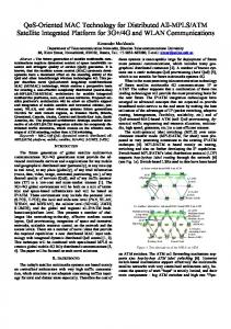
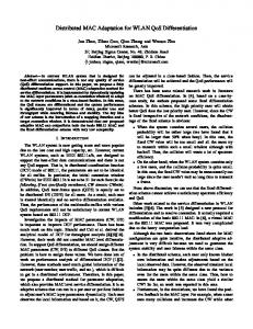
Scenario 1: A user on the node (1) requests different application services: (1) VoD service, (2) a simple ‘Hello World’ text return service, (3) a monitoring service, and (4) a concurrency service. Within this scenario, we illustrate the configuration overhead in terms of down-loading delay times when configuring and dynamically down-loading different sizes of service components. Figure 11 shows the result of different elapsed down-loading times for service components with sizes: 16.5 KB (concurrency service), 23.2 KB (text return service, version 1), 44.7 KB (text return service, version 2), 109.3 KB (VoD service), and 277.9 KB (monitoring service). The average elapsed down-loading times from the smallest to the largest service components are on average 134.29, 144.53, 161.46, 291.85 and 451.81 ms. Figure 12 illustrates the proportions of the down-loading times corresponding to the sizes of the service components.
500 "s2Concurrency-load" "s2Hello-load" "s2Hello1-load" "s2VOD-load" "s2Monitoring-load"
450
400
Time (ms)
350
300
250
200
150
100 0
5
10
15
20
25
Trail
Figure 11: Downloading Time for Different Application Services (Configuration Overhead)
Figure 13: QoS Setup Time (Runtime Instantiation)
Setup case 1 case 2
AtoC trans. 0.16ms 0.14ms
Svc. alloc. 565.71ms 873.54ms
Other 77.17ms 76.00ms
Total 643.05ms 949.70ms
500 "compare-load-g.txt" 450
Table 3 Average Setup Times for Two Different QoS Configurations
Scenario 3: The case (1) configuration of the VoD
350
300
250
200
150
100 0
50000
100000
150000 Library size
200000
250000
300000
Figure 12: Relation between Service Component Size and Down-loading Overhead
Scenario 2:
The VoD application is requested by a user. Within this scenario, we demonstrate instantiation times used for two different QoS configurations : case (1) VoD server connects to the VoD client directly, and case (2) VoD server connects to the VoD client via its gateway. The results in Figure 13 show that the smallest overhead comes from the application-to-component (AtoC) translation time which is currently implemented as the lookup of pre-specified QoS compilations. The largest overhead is the service allocation time which deals mainly with dynamic down-loading of service components on distributed nodes. QoS setup in case (2) needs more time for service allocation than the QoS setup in case (1). The reason is that in case (2) not only VoD client and VoD server are allocated on the client and the server nodes respectively, but also transcoding service has to be allocated on the VoD gateway node. Values plotted in the Figure 13 come from the average values of 25 trials presented in the Table 3.
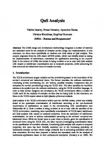
application is switched to the case (2) configuration. Within this scenario, we illustrate the reconfiguration overhead of the functional adaptation, represented by the runtime service component insertion. Figure 14 shows the reconfiguration overhead with 25 trails of a media gateway component insertion. The size of the media gateway service component is 110 KB. The average reconfiguration time is 301.73 ms. Comparing the results in this scenario with the results in scenario 1, we can conclude that the major overhead of the functional adaptation comes from the dynamic downloading time which varies mainly due to the service component’s size. "reconfiguration-time" 340
320
Time (ms)
Loadind time (ms)
400
300
280
260
0
5
10
15
20
Trail
Figure 14: Reconfiguration Overhead for a VoD Application
VII. R ELATED W ORK Different research groups consider middleware-based QoS provision. Some propose the QoS provision
functionalities as a middleware itself while others propose QoS functions as services in a middleware. Washington University’s TAO system [15] developed real-time CORBA-compliant ORB focusing on the optimization of real-time method invocations in the ORB itself. OMG’s Audio/Video Streaming and Messaging Services [16, 13] have been proposed for QoS provision in distributed multimedia applications and object invocations, respectively. Microsoft’s COM Non-Blocking method calls [17] provide asynchronous method invocation similar to OMG’s Messaging Service. BBN’s QuO project [6, 7], integrated with AQuA [18] framework provides fault tolerance and dependability QoS for CORBA objects invocations. While BBN mentioned broader range of QoS parameters extending from multimedia applications such as frame rate and frame size to other QoS parameters such as security level, reliability, and availability, they do not consider a unified reconfigurable QoS framework. University of Illinois’ EPIQ project [19] proposes an end-to-end QoS management architecture which manages different dimensions of QoS. This work is theoretically interesting and shares the same goal of our resource translation; however, it does not address QoS provision for distributed component-based systems. Lancaster’s Adapt project [5] provides an adaptation QoS middleware via open bindings. QoS management is done directly via manipulations of object graphs which represent the underlying end-to-end communication path. While Adapt project shares parts of our QoS framework’s objective, they do not consider QoS provision for different application domains. �� � While our framework shares the same goal as the CMU’s Darwin project [20] to provide applicationoriented QoS, based on underlying resource management mechanisms, our framework provides a complete methodology for QoS compilation and runtime instantiation as well as concrete models for the application-to-component QoS translation, dynamic service configuration, distributed resource allocation and reservation, and integrated QoS adaptations.
VIII. C ONCLUSION
�� � , is Our component-based QoS framework, �� � a light-weighted, reconfigurable framework. is light-weighted in the sense that it can be tailored to run on different nodes with different resource availability flexibly. The running application, using this framework, is also light-weighted and receives services and resources according to its request. It means that with our framework we can provide a “What you need is what you get” behavior. Furthermore, our results indicate that the framework is flexible and effective. The application-to-component
QoS-aware translation during the QoS compilation phase helps the runtime phase to provide multiple levels of QoS aspects for different application domains in an efficient, speedy and flexible manner. Flexibility is also supported by the availability of adaptive component-based applications and reconfigurable middleware. The integrated adaptation model provides a broader range of adaptations to satisfy a user’s QoS requirements. In summary, the partition of the end-to-end QoS setup process into QoS compilation and runtime QoS instantiation phases proved to be a very useful approach to achieve a unified QoS framework for different applications. Our presented methodology towards a unified QoS framework also triggers new research directions in areas such as QoS specification, QoS compilers, distributed QoS configurations, and others which we will be pursuing in the future work.
IX. R EFERENCES [1] K. Nahrstedt and J.M. Smith. The QoS Broker. IEEE Multimedia, 2(1), 1995. [2] R. Rajkumar, C. Lee, J. Lehoczky, and D. Siewiorek. A Resource Allocation Model for QoS Management. In Proceedings of the IEEE Real-Time Systems Symposium, December 1997. [3] A. Campbell, G. Coulson, and D. Hutchison. A Quality of Service Architecture. Computer Communication Review, April 1994. [4] A. Campbell, A. Lazar, H. Schulzinne, and R. Stadler. Building Open Programmable Multimedia Networks. Computer Communications Journal, June 1998. [5] G. Coulson, G.S. Blair, N. Davies, P. Robin, and T. Fitzpatrick. Suppoting Mobile Multimedia Applications Through Adaptive Middleware. IEEE journal on selected areas in communications, 17, September 1999. [6] J. Zinky, D. Bakken, and R. Schantz. Overview of Quality Service for Distributed Objects. Proceedings of the Fifth IEEE Dual Use Conference, 1995. [7] J. Zinky, D. Bakken, and R. Schantz. Architecture Support for Quality of Service for CORBA Objects . Theory and Practice of Object Systems, January 1997. [8] M. Roman, F. Kon, and R.H. Campbell. Design and Implementation of Runtime Reflection in Communication Middleware: the dynamicTAO case. ICDCS’99 Workshop on Middleware, June 1999. [9] F. Kon, A. Singhai, R.H. Campbell, D. Carvalho, R. Moore, and F. Ballesteros. 2K: A Reflective, Component-Based Operating System for Rapidly Changing Environments. Proceedings of ECOOP’98 Workshop on Reflective ObjectOriented Programming and Systems, July 1998. [10] K. Nahrstedt, H. Chu, and S. Narayan. QoS-Aware Resource Management for Distributed Multimedia Applications. Journal of High-Speed Networks, Special Issue on Multimedia Networking, 7, 1998. [11] H. Chu and K. Nahrstedt. CPU Service Classes for Multimedia Applications. Proceedings of IEEE International
[12]
[13]
[14]
[15]
[16]
[17] [18]
[19]
[20]
Conference on Multimedia Computing and Systems (IEEE ICMCS ’99), June 1999. K. Kim and K. Nahrstedt. QoS Translation and Admission Control for MPEG Video. 5th International Workshop on Quality of Service (IWQoS’97), 1997. BEA Systems Inc., Expersoft Corporation, Imprise Corporation, International Business Machine Corporation, International Computers Ltd., IONA Technologies Plc., Northern Telecom Corpoaration, Novell Inc., Oracle Corporation, Peerlogic Inc., and TIBCO Inc. CORBA Messaging. online documentation at http://www.omg.org/cgibin/doc?orbos/98-05-05., May 1998. B. Li and K. Nahrstedt. A Control-based Middleware Framework for Quality of Service Adaptation. IEEE JSAC, September 1999. D. Schmidt, D.Levine, and C. Cleeland. Architectures and Patterns for High-performance, Real-time CORBA Object Request Brokers, (updated September 19th). Advances in Computers, Academic Press, Ed., Marvin Zelkowitz, to appear. IONA Technologies Plc., Lucent Technologies Inc., and AG Siemens-Nixdorf. Control and Management of Audio/Video Streams OMG RFP Submission. online documentation at http://www.omg.org/docs/telecom/98-105.doc, May 1998. Micorsoft Corporation B. Sabino. Non-Blocking Method calls. Microsoft Corporation white paper, August 1999. M. Cukier, J. Ren, C. Sabnis, D. Henke, J. Pistole, W. H. Sanders, D. E. Bakken, M. Berman, D. Karr, and R. Schantz. AQuA: An Adaptive Architecture That Provides Dependable Distributed Objects. Proceedings of the 17th IEEE Symposium on Reliable Distributed Systems (SRDS’98), October 1998. M. Shankar, M. DeMiguel, and J. Liu. An End-to-End QoS Management Architecture. Proceedings of IEEE RTAS’99, June 1999. P. Chandra, A. Fisher, C. Kosak, T. Ng, P. Steenkiste, E. Takahashi, and H. Zhang. Darwin: Resource Management for Value-Added Customizable Network Service. Proceedings of IEEE ICNP’98, October 1998.