This article has been accepted for publication in a future issue of this journal, but has not been fully edited. Content may change prior to final publication. Citation information: DOI 10.1109/TPEL.2017.2785218, IEEE Transactions on Power Electronics
Distributed Power System Virtual Inertia Implemented by Grid-Connected Power Converters Jingyang Fang, Student Member, IEEE, Hongchang Li, Member, IEEE, Yi Tang, Member, IEEE, Frede Blaabjerg, Fellow, IEEE Abstract—Renewable energy sources (RESs), e.g. wind and solar photovoltaics, have been increasingly used to meet worldwide growing energy demands and reduce greenhouse gas emissions. However, RESs are normally coupled to the power grid through fast-response power converters without any inertia, leading to decreased power system inertia. As a result, the grid frequency may easily go beyond the acceptable range under severe frequency events, resulting in undesirable loadshedding, cascading failures, or even large-scale blackouts. To address the ever-decreasing inertia issue, this paper proposes the concept of distributed power system virtual inertia, which can be implemented by grid-connected power converters. Without modifications of system hardware, power system inertia can be emulated by the energy stored in the dc-link capacitors of grid-connected power converters. By regulating the dc-link voltages in proportional to the grid frequency, the dc-link capacitors are aggregated into an extremely large equivalent capacitor serving as an energy buffer for frequency support. Furthermore, the limitation of virtual inertia, together with its design parameters, are identified. Finally, the feasibility of the proposed concept is validated through simulation and experimental results, which indicate that 12.5% and 50% improvements of the frequency nadir and rate-of-change-offrequency (RoCoF) can be achieved. Index Terms—Frequency regulation, renewable energy source (RES), power converter, power system, virtual inertia.
I.
INTRODUCTION
I
NCREASING demands for the reduction of carbon footprint necessitate the large-scale integration of renewable energy, leading to a dramatic change of modern power systems. In particular, power system inertia provided by the rotating masses of synchronous generators continues to decrease. The reason is that renewable energy sources (RESs), e.g. wind and solar photovoltaics, are normally coupled to the power grid through fast-response power converters, which do not possess any inertia [1]. However, Manuscript received May 11, 2017; revised October 16, 2017; accepted December 11, 2017. This research is supported by the National Research Foundation, Prime Minister’s Office, Singapore under the Energy Programme and administrated by the Energy Market Authority (EP Award No. NRF2015EWT-EIRP002-007). The paper has been presented in part in [28]. (Corresponding author: Yi Tang) J. Fang and Y. Tang are with the School of Electrical and Electronic Engineering, Nanyang Technological University, Singapore 639798 (e-mail:
[email protected];
[email protected]). H. Li is with the Energy Research Institute @ NTU (ERI@N), Nanyang Technological University, Singapore 639798 (e-mail:
[email protected]). F. Blaabjerg is with the Department of Energy Technology, Aalborg University, Aalborg 9220, Denmark (e-mail:
[email protected]).
high power system inertia, i.e. large kinetic energy buffer, is usually desired as it can slow down the dynamics of frequency change and reduce frequency deviations, which effectively avoid undesirable load-shedding, cascading failures, or large-scale blackouts under frequency events [2]. To address the ever-decreasing inertia issue, several potential solutions have been proposed. Since power system inertia is mainly provided by the rotating masses of synchronous generators, one straightforward way to increase power system inertia is to run multiple synchronous generators at partial load conditions so that collectively they can provide high power system inertia even in the presence of large-scale renewable generation [3]. Although being effective in increasing inertia, such a solution will inevitably lead to higher capital and operating costs due to the increased rotating reserve. Instead of using back-up synchronous generators, grid-scale energy storage devices such as batteries, supercapacitors, and flywheels can flexibly be installed to compensate for frequency deviations. As an example, an independent energy storage system was employed to provide frequency support in electrical islands with high shares of RESs in [2]. Besides, energy storage devices can also be incorporated into renewable generation systems to mitigate their output power fluctuations and power system frequency deviations. In [4] and [5], supercapacitors were used to smooth the power output and improve the frequency regulation of DFIG-based wind power and PV generation, respectively. Even though the adoption of energy storage allows fast response (milliseconds) to frequency events, it may also bring in other concerns, e.g. low roundtrip efficiency, limited lifecycle, safety, and noises. It is highly desirable that the enhancement of power system inertia can be achieved through proper regulation of existing system resources. In modern power systems, gridconnected power converters have been widely used and found applications in many energy efficient loads and power conditioning devices, e.g. variable speed drives, switchedmode power supplies, active power filters (APFs), and static VAR generators (SVGs), etc. [6], [7]. For these applications, the dc-link capacitors are always necessary for voltage support and harmonics filtering [8], [9], and can be regarded as energy buffers. During frequency events, these energy buffers may potentially provide support to frequency regulation. Through proper control of grid-connected
0885-8993 (c) 2017 IEEE. Translations and content mining are permitted for academic research only. Personal use is also permitted, but republication/redistribution requires IEEE permission. See http://www.ieee.org/publications_standards/publications/rights/index.html for more information.
This article has been accepted for publication in a future issue of this journal, but has not been fully edited. Content may change prior to final publication. Citation information: DOI 10.1109/TPEL.2017.2785218, IEEE Transactions on Power Electronics
converters, this paper proposes the virtual inertia concept to improve power system frequency regulation by inertia emulation, and the emulated virtual inertia is essentially generated by an extremely large equivalent capacitor composed of many dc-link capacitors distributed in multiple grid-connected power converters. The proposed concept can easily be implemented without increasing system cost and complexity. Another well-known means of producing virtual inertia is to operate grid-connected inverters as synchronous generators. This concept is known as virtual synchronous machines (VSMs) or virtual synchronous generators (VSGs) [10] − [20]. The objective of VSGs is to function the same as synchronous generators so that the well-established theory for traditional power systems can still be valid for modern power systems with a high penetration level of renewable generation [10]. In this sense, the virtual inertia of VSGs should be designed the same as the inertia of synchronous generators [13] − [16]. However, being different from synchronous generators, VSGs can modify the virtual inertia dynamically by microprocessors during frequency events. As proposed in [17], self-tuning algorithms were employed to continuously change the virtual inertia in order to minimize the frequency deviation and power output of the VSG. Similar ideas can be found in [18] and [19], where two different values of virtual inertia were alternatively used to improve the dynamics of frequency regulation. Although arbitrarily assigning the virtual inertia of VSGs can be simple and straightforward, it is based on the assumption that VSGs can output or absorb infinitely large power, which is far from
being proven. In fact, in order to produce the desired inertia, energy storage units have to be incorporated into VSGs, resulting in increased system complexity and reduced system efficiency. Without energy storage, the virtual inertia of VSGs would be limited by their dc-link capacitances, as pointed out by [20], [21]. However, the exact relationship between the virtual inertia and dc-link capacitances as well as other design parameters have so far not been disclosed by previous research. The quantitative analysis of the virtual inertia presented in this paper will fill this gap. II.
SYSTEM STRUCTURE AND INERTIA ANALYSIS
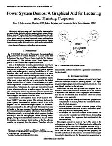
A. System Structure The simplified schematic diagram of a single-area power system is shown in Fig. 1, where Pm stands for the power generated by synchronous generators, PL denotes the power consumed by frequency-independent resistive-loads, PD represents the power absorbed by frequency-dependent loads, e.g. induction motors, and Pdc refers to the power absorbed by grid-connected power converters, namely the power consumed by ac/dc rectifiers minus the power generated by dc/ac inverters. It should be mentioned that the variability of renewable generation is lumped together with load changes, and thus Pdc is assumed to be a constant unless frequency events occur. When frequency events happen, the fundamental idea behind the proposed concept is to directly link Pdc with the grid frequency fr (fr equals the angular frequency ωr in per-unit forms). The power absorption (generation) versus frequency characteristics of electric loads (synchronous generators) are illustrated in Fig. 1, where R
Fig. 1. Simplified schematic diagram of a single-area power system.
0885-8993 (c) 2017 IEEE. Translations and content mining are permitted for academic research only. Personal use is also permitted, but republication/redistribution requires IEEE permission. See http://www.ieee.org/publications_standards/publications/rights/index.html for more information.
This article has been accepted for publication in a future issue of this journal, but has not been fully edited. Content may change prior to final publication. Citation information: DOI 10.1109/TPEL.2017.2785218, IEEE Transactions on Power Electronics
designates the frequency droop coefficient. Its function is to properly share the load power among various synchronous generators according to their respective power ratings [22]. Hp represents the virtual inertia coefficient of grid-connected power converters, which will be discussed in Section III. D denotes the damping factor of frequency-dependent loads. The prefix Δ, subscript ref, and subscript pu denote the changes, references, and per-unit values (the ratios of real values to rated values) of relevant parameters, respectively. First, it is assumed that there is no virtual inertia obtained from grid-connected power converters, and thus Pdc is a constant Pdc_ref. Under this condition, the grid frequency is solely regulated by synchronous generators. The corresponding block diagram of frequency regulation is shown in Fig. 2, where TG represents the time constant of the speed governor and FHP, TRH and TCH are the coefficients of the reheat turbine [3]. It should be mentioned that the linearized frequency regulation structure shown in Fig. 2 is only applicable to the small-signal analysis, where the grid frequency fr is around its nominal value fref. In Fig. 2, the inertia and load block describes the wellknown swing equation, which models the electromechanical behavior of synchronous generators, and it can be expressed as [3]: dr_pu Pm_pu PL_pu 2 H Dr_pu , (1) dt
Fig. 2. Block diagram of frequency regulation without virtual inertia.
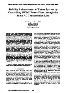
where H = Egen / VArated = Jωref2 / (2VArated) represents the perunit inertia coefficient, Egen denotes the kinetic energy, J stands for the combined moment of inertia of the generator and turbine, and VArated represents the system base power. The frequency regulation structure shown in Fig. 2 and the relevant system parameter values, as tabulated in Table I, can be found in [3]. It should be noted that frequency regulation performances are not constrained by the power ratings of synchronous generators and power converters. In other words, the frequency response of a 1-MVA system can be the same as that of a 1-kVA system so long as their parameters are equivalent in per-unit forms. B. Inertia Analysis The objective of this subsection is to quantify the influence of power system inertia on frequency regulation. To achieve this objective, the transfer function from the load disturbance ΔPL_pu to the frequency deviation Δωr_pu is derived from Fig. 2 and expressed as: r_pu GPL r ( s ) PL_pu (2) R(1 sTG )(1 sTCH )(1 sTRH ) . (2 Hs D)(1 sTG )(1 sTCH )(1 sTRH ) R sFHPTRH 1 The pole-zero map and frequency responses of (2) under a 3% step-up load change are drawn in Fig. 3, where zeros are denoted as circles and poles are represented as crosses. It should be noted that unlike power electronic systems where 100% load step changes may occur, the step changes in power systems are mainly caused by the loss of generators or load shedding, and a 3% to 5% load change is considered to be a large disturbance to power systems [2], [14]. It can be observed from Fig. 3(a) that the poles P3 and P4 gradually approach and tend to cancel out the zeros Z2 and Z3, respectively, as the inertia coefficient H increases. Consequently, the frequency responses are mainly determined by the dominating zero Z1 as well as the
Table I. System parameter values. Synchronous generator Symbol
Description
Power converter Value
Symbol
Description
Value
R
Droop coefficient
0.05
Vdc
Rated dc-link voltage
400 V
TG
Speed governor coefficient
0.1 s
Vdc_max
Maximum dc-link voltage
436 V
FHP
Turbine HP coefficient
0.3 s
Vdc_min
Minimum dc-link voltage
364 V
TRH
Time constant of reheater
7.0 s
ΔVdc_max
Maximum voltage deviation
36 V
TCH
Time constant of main inlet volumes
0.2 s
KPWM
PWM gain
1
H
Inertia coefficient of SG
5.0 s
Hp
Virtual inertia coefficient
5.0 s
fref
Rated frequency
50 Hz
Cdc
Dc-link capacitance
2.82 mF
Δfr_max
Maximum frequency deviation
0.2 Hz
Δfr_max
Maximum frequency deviation
0.2 Hz
D
Damping coefficient
1.0
Kωv / Kωv_pu
Frequency controller
180 / 22.5
VArated
Power rating
1 MVA
VArated
Power rating
1000 × 1 kVA
0885-8993 (c) 2017 IEEE. Translations and content mining are permitted for academic research only. Personal use is also permitted, but republication/redistribution requires IEEE permission. See http://www.ieee.org/publications_standards/publications/rights/index.html for more information.
This article has been accepted for publication in a future issue of this journal, but has not been fully edited. Content may change prior to final publication. Citation information: DOI 10.1109/TPEL.2017.2785218, IEEE Transactions on Power Electronics
a step-up load change, the grid frequency can be expressed in the s domain as: ( s) G f r _pu ( s ) f ref _pu ( s ) PL r s Reference
Deviation
d z1 1 ( s ) 2 2 2 n d n 1 d G0 , s n d s n 1 s ( s n ) 2 d 2 d ( s n ) 2 d 2 (5) where fref_pu(s) = 1 / s and GPL→ωr(s) / s are introduced by the per-unit frequency reference and frequency deviation, respectively, and ωd stands for the damped frequency, which can be represented as:
(a) Pole-zero map
d n 1 2 .
(b) Frequency responses Fig. 3. Pole-zero map and frequency responses of GPL→ωr(s) under a 3% step-up load change (H = 5, 10, 20, and 50).
conjugate poles P1 and P2. Characterizing the system by Z1, P1, and P2, (2) can be simplified into: R(1 sTRH ) GPL r ( s ) (2 Hs D)(1 sTRH ) R sFHPTRH 1 (3) s z1 G0 2 , s 2n s n 2 where 1 1 G0 , z1 , n 2H TRH
DR 1 , 2 HRTRH
2 HR DRTRH FHPTRH 2 HRTRH , 4 HRTRH DR 1
(4)
where ωn and ζ respectively represent the undamped natural frequency and damping ratio. Comparisons between the step responses of GPL→ωr(s) expressed in (2) and its simplified form represented in (3) are shown in Fig. 3(b). It is clear that the maximum differences between these two cases are always less than 10% frequency deviations, and this validates the effectiveness of the proposed simplified model. Considering
(6) By taking the inverse Laplace transform of (5), the expression of frequency in the time domain can be derived as: z f r _pu (t ) 1 G0 12 e nt A sin(d t ) , (7) n where z n 2 d z1 z ) , arctan A ( 12 ) 2 ( 1 . (8) n d n ( z1 n )n Based on (7), several important performance indices for evaluating frequency regulation can easily be derived. For example, the rate of change of frequency (RoCoF) can be obtained by differentiating (7) with respect to time as: nent A sin(d t ) d (9) f r _pu (t ) G0 t . n dt Ad cos(d t ) e Furthermore, the peak time tpeak can be derived by setting (9) to be zero: 1 2 1 tpeak arctan( ) . (10) d Substituting (10) into (7), the frequency nadir fr_peak_pu, i.e. the peak frequency, can be derived as: Gz t (11) f r _ peak_pu 1 0 21 G0 e n peak A 1 2 .
n
The first two terms of (11) collectively represent the quasisteady-state frequency fr_∞_pu, which can be represented as: Gz R f r _ _ pu 1 0 21 1 . (12) DR 1 n It is noted from (12) that the inertia coefficient H has no effect on the quasi-steady-state frequency deviation. However, as indicated by (4), (9), and (11), H will definitely influence the RoCoF and frequency nadir. The frequency deviation may also be evaluated by the frequency overshoot σ, which can be derived from (11) as:
0885-8993 (c) 2017 IEEE. Translations and content mining are permitted for academic research only. Personal use is also permitted, but republication/redistribution requires IEEE permission. See http://www.ieee.org/publications_standards/publications/rights/index.html for more information.
This article has been accepted for publication in a future issue of this journal, but has not been fully edited. Content may change prior to final publication. Citation information: DOI 10.1109/TPEL.2017.2785218, IEEE Transactions on Power Electronics
e
f r _ _pu f r _ peak_pu f r _ _pu
100%
ntpeak
A 1 2 n 2 100%. 2 H n 2 z1
(13)
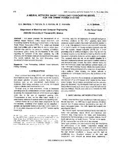
Additionally, the settling time (time for entering the 2% quasi-steady-state error band) is normally used to evaluate the dynamics of frequency regulation, which can be derived as: f r_pu (ts ) f r _ _pu 2 e nts A 2% n 2% 1 f r _ _pu z1 (14) 0.02 z1 1 ts ln( ). n An 2 Based on (9) − (14), the relationships between various performance indices and the inertia coefficient H are demonstrated in Fig. 4. As observed from Fig. 4(a) and (b), an increase of inertia leads to the decreased RoCoF |dfr / dt|t = 0 s and increased fr_peak, thereby proving the effectiveness of power system inertia in suppression of the frequency
deviation and its time derivative. Obviously, larger changes of loads will give rise to more serious cases of RoCoF and frequency nadir, which should properly be addressed to prevent unfavorable load shedding. As suggested by Fig. 4(c), the frequency overshoot can well be attenuated by a large value of H. Although being effective in attenuating the RoCoF and frequency deviation, high power system inertia will inevitably slow down the dynamics of frequency regulation and extend the frequency restoration process, as evidenced by Fig. 4(d). Consequently, trade-offs between the frequency deviation and settling time are required for designing the inertia coefficient H. Theoretically, the inertia coefficient should be designed according to the requirements of the performance indices expressed in (9) – (14) and shown in Fig. 4. In general, a larger H improves frequency regulation as it translates into a smaller frequency deviation and RoCoF. III.
IMPLEMENTATION OF DISTRIBUTED VIRTUAL INERTIA BY GRID-CONNECTED POWER CONVERTERS
The previous section has revealed that the increased inertia allows an improvement of frequency regulation. This section aims to further detail the proposed concept for
(a) RoCoF |df / dt|t = 0 s
(b) Frequency nadir fr_peak
(c) Overshoot σ
(d) Settling time ts
Fig. 4. Relationships between various performance indices and the inertia coefficient H under a 3% step-up load change.
0885-8993 (c) 2017 IEEE. Translations and content mining are permitted for academic research only. Personal use is also permitted, but republication/redistribution requires IEEE permission. See http://www.ieee.org/publications_standards/publications/rights/index.html for more information.
This article has been accepted for publication in a future issue of this journal, but has not been fully edited. Content may change prior to final publication. Citation information: DOI 10.1109/TPEL.2017.2785218, IEEE Transactions on Power Electronics
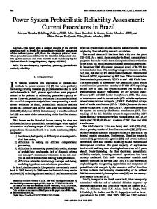
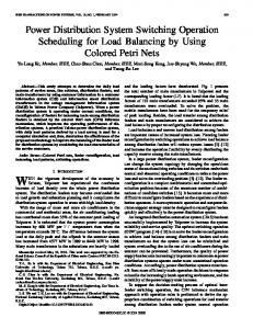
enhancing power system inertia. Conventionally, power system inertia is solely provided by the kinetic energy stored in the rotors of synchronous generators, and the relevant inertia coefficient can be expressed as: H = Egen / VArated = Jωref2 / (2VArated), as already mentioned. The fundamental idea behind the proposed concept is to emulate power system inertia by the energy stored in the dc-link capacitors of gridconnected power converters. Similar to H, the inertia coefficient of dc-link capacitors Hc can be expressed as the ratio of the capacitor energy to the system base power: Ecap C V 2 Hc dc dc , (15) VArated 2VArated where Ecap denotes the capacitor energy, Cdc represents the capacitance, and Vdc stands for the rated dc-link voltage. Fig. 5 visualizes the similarities between synchronous generators and dc-link capacitors. It can be noted that the energy and inertia coefficients are in proportion to the square of ωref (fref) or Vdc. In this sense, the dc-link voltage vdc and frequency fr function similarly. Inspired by this observation, vdc and fr are directly linked for generating distributed virtual inertia in this paper. Fig. 6 illustrates the structure of the grid-connected power converter equipped with distributed virtual inertia. As seen, the grid voltages vgx (x = a, b, c) are synchronized by a phase-
Fig. 5. Analogy between synchronous generators and dc-link capacitors.
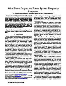
Fig. 6. Structure of the grid-connected power converter equipped with virtual inertia.
locked-loop (PLL), which provides the grid frequency and phase-angle for dq-frame current control [1]. Generally, double-loop controllers, i.e. outer voltage-loop and inner current-loop controllers, are used for regulation of gridconnected converters. The dc-link voltage vdc can be regulated to its reference vdc_ref by controlling the d-axis reference current id_ref, while the q-axis reference current iq_ref is dependent on the requirement of reactive power compensation [6]. The virtual inertia is introduced by the proposed frequency controller, whose transfer function is represented as Kωv(s). It links fr and vdc such that the change of frequency Δfr will lead to a change of dc-link voltage Δvdc, which further causes the change of power ΔPdc of the power converter. Without employing additional energy sources in the dc-link, the proposed concept uses the energy stored in the dc-link capacitors of grid-connected power converters. Since the dc-link capacitors are always necessary in power converters for harmonics filtering and voltage support, the proposed frequency control brings in no extra cost in terms of system hardware. When the frequency controller is disabled, the block diagram of conventional double-loop controllers can be obtained, as shown in Fig. 7, where a proportional-integral (PI) controller and a proportional (P) controller are incorporated respectively for voltage and current control while the coupling effect between the d- and q-axis is ignored. It is worth mentioning that the closed-loop transfer function from vdc_ref to vdc is denoted as Gclv(s), whose response time normally ranges from 0.01 s to 0.1 s [1]. Additionally, the range of vdc must be confined to [Vdc_min, Vdc_max], where the minimum voltage Vdc_min is to ensure the linear modulation of power converters, and it can be improved by injecting a third-harmonic term into the modulating references [24]. In contrast, the maximum voltage Vdc_max is determined by the voltage ratings of active and passive components. When the proposed frequency controller is activated, the block diagram of frequency regulation depicted in Fig. 2 is modified into Fig. 8, where Δvdc_pu is related to ΔPdc_pu through a transfer function of 2Hcs, Gclv(s) denotes the closed-loop transfer function of voltage control, and Kωv_pu(s) represents the proposed frequency controller in its per-unit form. In this case, the equivalent inertia coefficient is changed from H into H + HcGclv(s)Kωv_pu(s), where the second term can be regarded as the virtual inertia coefficient Hp, which can be expressed as: H p H c Gclv ( s) Kv_pu ( s). (16) Since the dynamics of voltage control is much faster than that of frequency control, Gclv(s) can be approximated to be one. As a result, it is possible to design Kωv_pu(s) as a proportional controller for generating the virtual inertia: Vdc _ max f r _ max Kv_pu ( )/( ), (17) Vdc f ref where ΔVdc_max = (Vdc_max − Vdc_min) / 2 and Δfr_max respectively denote the maximum allowable voltage
0885-8993 (c) 2017 IEEE. Translations and content mining are permitted for academic research only. Personal use is also permitted, but republication/redistribution requires IEEE permission. See http://www.ieee.org/publications_standards/publications/rights/index.html for more information.
This article has been accepted for publication in a future issue of this journal, but has not been fully edited. Content may change prior to final publication. Citation information: DOI 10.1109/TPEL.2017.2785218, IEEE Transactions on Power Electronics
Fig. 7. Block diagram of conventional double-loop controllers for grid-connected power converters.
Fig. 8. Block diagram of frequency regulation with virtual inertia.
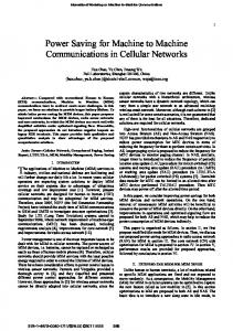
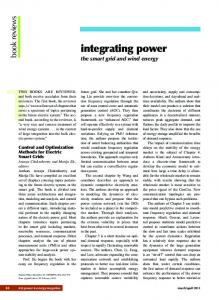
deviation and frequency deviation. It should be noted that the system parameters shown in Fig. 8 are referred to their perunit forms. Therefore, ΔVdc_max and Δfr_max should be divided by the rated dc-link voltage Vdc and frequency fref, respectively. Substituting (15) and (17) into (16), the virtual inertia coefficient Hp can be reorganized as: Vdc_max f ref CdcVdc 2 (18) Hp . Vdc f r_max 2VArated From (18), the virtual inertia coefficient under a certain power rating is limited by the following factors: dc-link capacitance Cdc, rated dc-link voltage Vdc, maximum voltage variation ratio ΔVdc_max / Vdc, and maximum frequency variation ratio Δfr_max / fref. For a 1-kVA power converter with its maximum frequency deviation Δfr_max = 0.2 Hz (fref = 50 Hz), the virtual inertia coefficient Hp versus Cdc, Vdc, and ΔVdc_max is illustrated in Fig. 9. It is clear from Fig. 9 that Hp increases along with the increase of Cdc, Vdc, and ΔVdc_max. Furthermore, it is possible for power converters to generate even larger virtual inertia than the inertia produced by synchronous generators (H normally ranges from 2 to 10 [2], [3]). However, larger Cdc and Vdc will inevitably increase the system size and cost, and a higher ΔVdc_max may bring in over modulation issues. Based on the aforementioned analysis, a design flowchart of virtual inertia is illustrated in Fig. 10. As seen, in the first step, the requirements of performance indices, e.g. the RoCoF |df / dt|t = 0 s and frequency nadir fr_peak, should be determined. With these requirements, it is possible to derive the desired inertia coefficient from Fig. 4 in the second step. Since the desired inertia coefficient equals the sum of the power system inertia coefficient H and virtual inertia coefficient Hp, Hp can readily be obtained upon knowing H
in the third step. In the fourth step, the system parameters VArated, fref, and Δfr_max should be provided. According to Fig. 9, the dc-link capacitance Cdc, rated dc-link voltage Vdc, and maximum voltage deviation ΔVdc are designed in the fifth step to obtain the predetermined Hp. If over modulation occurs, the redesign should be performed.
(a) ΔVdc_max / Vdc = 0.15
(b) Cdc = 2.82 mF Fig. 9. Virtual inertia coefficient Hp versus Cdc, Vdc, and ΔVdc_max (Δfr_max = 0.2 Hz, fref = 50 Hz, and VArated = 1 kVA).
0885-8993 (c) 2017 IEEE. Translations and content mining are permitted for academic research only. Personal use is also permitted, but republication/redistribution requires IEEE permission. See http://www.ieee.org/publications_standards/publications/rights/index.html for more information.
This article has been accepted for publication in a future issue of this journal, but has not been fully edited. Content may change prior to final publication. Citation information: DOI 10.1109/TPEL.2017.2785218, IEEE Transactions on Power Electronics
Fig. 10. Design flowchart of virtual inertia.
IV.
SIMULATION AND EXPERIMENTAL RESULTS
A. Simulation Results The proposed distributed virtual inertia concept has been successfully verified in simulations through the Matlab/Simulink software. As listed in Table I, ΔVdc_max = 36 V, Cdc = 2.82 mF, and Kωv_pu = 22.5 can be obtained. Under this condition, the resulting virtual inertia coefficient is Hp = 5.0 s, which is the same as the inertia coefficient of synchronous generators H = 5 s. In other words, replacing synchronous generators with the inverter-based renewable generators will not reduce power system inertia. System models without and with distributed virtual inertia have been constructed. The simulation results of their frequency responses when subjected to a 3% step-up load change are shown in Fig. 11 (with 50 Hz nominal frequency). As observed from Fig. 11(a), the maximum frequency deviation without the proposed method is around 0.16 Hz. In contrast, when the proposed frequency controller shown in Fig. 6 is activated, the maximum frequency deviation can be limited to be 0.14 Hz. Therefore, a 12.5% frequency deviation reduction is achieved with the proposed virtual inertia method. Moreover, another critical parameter – the RoCoF can be reduced from 0.150 Hz/s to 0.075 Hz/s,
indicating a 50% improvement over the case without virtual inertia. A high RoCoF value exceeding the limit, e.g. 1 Hz/s, may lead to tripping of protection relays and result in a large disturbance to the power system [23]. With the proposed method, the RoCoF is actually determined by power converters together with the inertia of power system, and it can flexibly be designed with the change of virtual inertia coefficient Hp. As seen from Fig. 11(b), the quasi-steady-state voltage deviation is around 13 V, which is in proportion to the quasi-steady-state frequency deviation, as verified by Fig. 11(a) and (b). Additionally, it should be noted that the frequency deviation is always less than 0.2 Hz. As a result, the corresponding voltage deviation is within the maximum allowable voltage deviation 36 V. Furthermore, Fig. 11(c) and (d) demonstrate the energy and power outputs of power converters during the frequency dynamics. As observed from Fig. 11(c), power converters output energy during the frequency event to provide frequency support. Moreover, it is clear from Fig. 11(d) that the proposed method would not interfere the normal operation of power converters, since their output powers are maintained as zero in quasi-steadystate. Similar observations can be obtained from Fig. 12, where the power system is subject to a 3% step-down load change. In this case, the grid frequency fr becomes larger than its nominal value fref during the frequency dynamics, which will accelerate the rotors and increase the mechanical stresses of synchronous generators. Fortunately, this issue can be resolved by adopting the proposed virtual inertia method. When this contingency happens, all the grid-connected power converters absorb energy from power grid (see Fig. 12(c)), leading to the increased dc-link voltages, as noted from Fig. 12(b). In quasi-steady-state, the power consumption also remains to be zero, as validated by Fig. 12(d). B. Experimental Results In order to further illustrate the effectiveness of the proposed concept, experiments were carried out based on the system schematic diagram shown in Fig. 13 and the system parameter values listed in Table I, except for the power rating, which was scaled down to 1-kVA. In the experiments, the synchronous generator was replaced by a virtual synchronous generator (VSG). The VSG is employed to emulate a synchronous generator so that the improvement of frequency regulation implemented by the grid-connected converter (GCC) can be validated. For stability analysis, detailed models of synchronous generators must be employed. In contrast, the simplified model of synchronous generators shown in Fig. 2 can be used to evaluate frequency regulation, because the mechanical time constants are much greater than the electrical time constants, whose effects on power system frequency dynamics can be ignored. In Chapter 11 of [3], the presented frequency regulation model is detailed with its effectiveness verified. Similar synchronous generator models can be found in [15], [25], [26], and [27] provides guidelines for VSG design. Additionally, only one
0885-8993 (c) 2017 IEEE. Translations and content mining are permitted for academic research only. Personal use is also permitted, but republication/redistribution requires IEEE permission. See http://www.ieee.org/publications_standards/publications/rights/index.html for more information.
This article has been accepted for publication in a future issue of this journal, but has not been fully edited. Content may change prior to final publication. Citation information: DOI 10.1109/TPEL.2017.2785218, IEEE Transactions on Power Electronics
(a) Frequency fr
(c) Energy −ΔEdc
(b) Dc-link voltage vdc
(d) Power −ΔPdc
Fig. 11. Frequency responses of the systems with and without virtual inertia (3% step-up load change).
GCC and one VSG were tested and designed using the same per-unit values as the real single-area power system, where the frequency signals seen by individual converters and generators are the same. Therefore, the system shown in Fig. 13 can be regarded as an aggregated model and it is dynamically equivalent to the simulated system presented in Section IV A. As seen from Fig. 13, the GCC equipped with distributed virtual inertia was connected in parallel with the VSG. Its detailed control structure can be found in Fig. 6 and Fig. 7. A photo of the experimental prototype is shown in Fig. 14. As seen, a dSPACE control platform (dSPACE: Microlabbox) was used to implement the control algorithms of both the VSG and GCC. The dc-link voltage vgdc of the VSG was maintained as a constant by a dc power supply (Itehc: IT6500C). This voltage was then converted into ac voltages vgx (x = a, b, c) to emulate grid voltages as well as supply a three-phase load with a resistance of Rl. Litz wires with low equivalent-series-resistances (ESR) were used as inductor windings. An oscilloscope (TELEDYNE LECROY:
HDO8038) was involved to capture the experimental waveforms and export them into Matlab/Simulink for further analysis. Fig. 15 demonstrates the steady-state waveforms of the grid voltages vgx and load currents ilx (x = a, b, c) when the proposed controller is activated. It is clear that these waveforms are perfect sinusoidal with low distortions thanks to the help of VSG control. Another observation is that the proposed virtual inertia method would not pose any threat to the normal operation of power grid. Fig. 16 shows the experimental results of the systems without and with the proposed virtual inertia when subjected to a 3% step-up load change. As seen from Fig. 16(a), when the proposed method is disabled, the dc-link voltage vdc remains unchanged while the maximum frequency deviation|fref – fr_peak| is around 0.17 Hz. This value can be reduced to 0.14 Hz after enabling the proposed frequency controller. Under this condition, the dc-link voltage vdc varies in proportional to the grid frequency fr. In addition, as verified
0885-8993 (c) 2017 IEEE. Translations and content mining are permitted for academic research only. Personal use is also permitted, but republication/redistribution requires IEEE permission. See http://www.ieee.org/publications_standards/publications/rights/index.html for more information.
This article has been accepted for publication in a future issue of this journal, but has not been fully edited. Content may change prior to final publication. Citation information: DOI 10.1109/TPEL.2017.2785218, IEEE Transactions on Power Electronics
(a) Frequency fr
(b) Dc-link voltage vdc
(c) Energy −ΔEdc
(d) Power −ΔPdc
Fig. 12. Frequency responses of the systems with and without virtual inertia (3% step-down load change).
Fig. 13. Schematic diagram of the experimental prototype.
by Fig. 16(b), the GCC outputs power and energy during the frequency dynamics to support frequency regulation, and then its output power deviation returns back to 0 W in quasisteady-state.
In contrast, Fig. 17 illustrates the experimental results of the systems without and with the proposed virtual inertia when subjected to a 3% step-down load change. Once again, the proposed frequency controller allows a 0.03 Hz reduction
0885-8993 (c) 2017 IEEE. Translations and content mining are permitted for academic research only. Personal use is also permitted, but republication/redistribution requires IEEE permission. See http://www.ieee.org/publications_standards/publications/rights/index.html for more information.
This article has been accepted for publication in a future issue of this journal, but has not been fully edited. Content may change prior to final publication. Citation information: DOI 10.1109/TPEL.2017.2785218, IEEE Transactions on Power Electronics
Fig. 14. Photo of the experimental prototype.
of the maximum frequency deviation |fref – fr_peak|. Under this circumstance, the GCC absorbs energy and power from the power grid to achieve frequency support. These experimental results are similar to the simulation results shown in Fig. 11 and Fig. 12. The predicted results, simulation results, and experimental results indicate that the inertia analysis method provided in Section II B are effective in predicting the values of major performance indices, particularly for the RoCoF, quasi-steady-state frequency, and dc-link voltage. The errors among the predicted values, simulation results, and experimental results may be caused by the inaccuracy of model simplification (see Fig. 3) and signal measurements. V.
Fig. 15. Experimental waveforms of the grid voltages vgx and load currents ilx (x = a, b, c).
(a) Frequency fr (top) and dc-link voltage vdc (bottom)
CONCLUSION
This paper has proposed a concept for grid-connected power converters to generate distributed virtual inertia, which can effectively increase power system inertia and reduce frequency deviations as well as the changing rate of grid frequency under large disturbances. The virtual inertia is emulated by the dc-link capacitors of grid-connected power converters without increasing system cost and complexity. Taking the grid frequency as a common signal, gridconnected power converters may easily modify their dc-link voltages proportionally. As a result, all the dc-link capacitors are aggregated into an extremely large equivalent capacitor for frequency support. Furthermore, the design parameters of virtual inertia, e.g. dc-link capacitance, dc-link voltage, and
(a) Frequency fr (top) and dc-link voltage vdc (bottom)
(b) Energy −ΔEdc (top) and power −ΔPdc (bottom)
(b) Energy −ΔEdc (top) and power −ΔPdc (bottom)
Fig. 16. Experimental results under a 3% step-up load change with and without virtual inertia.
Fig. 17. Experimental results under a 3% step-down load change with and without virtual inertia.
0885-8993 (c) 2017 IEEE. Translations and content mining are permitted for academic research only. Personal use is also permitted, but republication/redistribution requires IEEE permission. See http://www.ieee.org/publications_standards/publications/rights/index.html for more information.
This article has been accepted for publication in a future issue of this journal, but has not been fully edited. Content may change prior to final publication. Citation information: DOI 10.1109/TPEL.2017.2785218, IEEE Transactions on Power Electronics
maximum dc-link voltage deviation have been identified. The simulation and experimental results indicate that a 12.5% reduction of the frequency deviation and a 50% improvement of the rate of change of frequency (RoCoF) can be achieved by the proposed concept. REFERENCES [1]
[2]
[3] [4]
[5]
[6]
[7]
[8]
[9]
[10] [11]
[12]
[13]
[14]
[15]
[16]
[17]
F. Blaabjerg, R. Teodorescu, M. Liserre, and A. V. Timbus, “Overview of control and grid synchronization for distributed power generation systems,” IEEE Trans. Ind. Electron., vol. 53, no. 5, pp. 1398–1409, Oct. 2006. G. Delille, B. Francois, and G. Malarange, “Dynamic frequency control support by energy storage to reduce the impact of wind and solar generation on isolated power system’s inertia,” IEEE Trans. Sustain. Energy, vol. 3, no. 4, pp. 931–939, Oct. 2012. P. Kundur, Power System Stability and Control. New York, NY, USA: McGraw-Hill, 1994. M. Arani and E. Saadany, “Implementing virtual inertia in DFIG-based wind power generation,” IEEE Trans. Power System, vol. 28, no. 2, pp. 1373–1384, May 2013. N. Kakimoto, S. Takayama, H. Satoh, and K. Nakamura, “Power modulation of photovoltaic generator for frequency control of power system,” IEEE Trans. Energy Conv., vol. 24, no. 4, pp. 943−949, Dec. 2009. J. Fang, G. Xiao, X. Yang, and Y. Tang, “Parameter design of a novel series-parallel-resonant LCL filter for single-phase half-bridge active power filters,” IEEE Trans. Power Electron., vol. 32, no. 1, pp. 200– 217, Jan. 2017. B. Singh, B. N. Singh, A. Chandra, K. Al-Haddad, A. Pandey, and D. P. Kothari, “A review of three-phase improved power quality AC–DC converters,” IEEE Trans. Ind. Electron., vol. 51, no. 3, pp. 641−660, Jun. 2004. H. Wang and F. Blaabjerg, “Reliability of capacitors for DC-Link applications in power electronic converters−an overview,” IEEE Trans. Ind. Appl., vol. 50, no. 5, pp. 3569−3578, Sep./Oct. 2014. J. Fang, H. Li, and Y. Tang, “A magnetic integrated LLCL filter for grid-connected voltage-source converters,” IEEE Trans. Power Electron., vol. 32, no. 3, pp. 1725–1730, Mar. 2017. H.-P. Beck and R. Hesse, “Virtual synchronous machine,” in Proc. 9th Int. Conf. Elect. Power Qual. Util. (EPQU), 2007, pp. 1–6. J. Driesen and K. Visscher, “Virtual synchronous generators,” in Proc. IEEE Power Energy Soc. Gen. Meeting—Convers. Del. Elect. Energy 21st Century, Jul. 2008, pp. 1−3. Q. Zhong and G. Weiss, “Synchronverters: inverters that mimic synchronous generators,” IEEE Trans. Ind. Electron., vol. 58, no. 4, pp. 1259−1267, Apr. 2011. H. Wu, X. Ruan, D. Yang, X. Chen, W. Zhao, Z. Lv, and Q. Zhong, “Small-signal modeling and parameters design for virtual synchronous generators,” IEEE Trans. Ind. Electron., vol. 63, no. 7, pp. 4292−4303, Jul. 2016. J. Liu, Y. Miura, and T. Ise, “Comparison of dynamic characteristics between virtual synchronous generator and droop control in inverterbased distributed generators,” IEEE Trans. Power Electron., vol. 31, no. 5, pp. 3600−3611, May 2016. S. D'Arco and J. A. Suul, “Equivalence of virtual synchronous machines and frequency-droops for converter-based microgrids,” IEEE Trans. Smart Grid, vol. 5, no. 1, pp. 394−395, Jan. 2014. Y. Hirase, K. Sugimoto, K. Sakimoto, and T. Ise, “Analysis of resonance in microgrids and effects of system frequency stabilization using a virtual synchronous generator,” IEEE J. Emerg. Sel. Topics Power Electron, vol. 4, no. 4, pp. 1287−1298, Dec. 2016. M. A. Torres L, L. A. C. Lopes, L. A. Moran T, and J. R. Espinoza C, “Self-tuning virtual synchronous machine: a control strategy for energy storage systems to support dynamic frequency control,” IEEE Trans. Energy Conv., vol. 29, no. 4, pp. 833−840, Dec. 2014.
[18] D. Li, Q. Zhu, S. Lin, and X. Y. Bian, “A self-adaptive inertia and damping combination control of VSG to support frequency stability,” IEEE Trans. Energy Conv., vol. 32, no. 1, pp. 397−398, Mar. 2017. [19] J. Alipoor, Y. Miura, and T. Ise, “Power system stabilization using virtual synchronous generator with alternating moment of inertia,” IEEE J. Emerg. Sel. Topics Power Electron, vol. 3, no. 2, pp. 451−458, Jun. 2015. [20] L. Xiong, F. Zhuo, F. Wang, X. Liu, Y. Chen, M. Zhu, and H. Yi, “Static synchronous generator model: a new perspective to investigate dynamic characteristics and stability issues of grid-tied PWM inverter,” IEEE Trans. Power Electron., vol. 31, no. 9, pp. 6264−6280, Sep. 2016. [21] M. Ashabani and Y. A.-R. I. Mohamed, “Novel comprehensive control framework for incorporating VSCs to smart power grids using bidirectional synchronous-VSC,” IEEE Trans. Power Syst., vol. 29, no. 2, pp. 943−957, Mar. 2014. [22] J. M. Guerrero, J. C. Vasquez, J. Matas, L. G. Vicuna, and M. Castilla, “Hierarchical control of droop-controlled AC and DC microgrids–a general approach toward standardization,” IEEE Trans. Ind. Electron., vol. 58, no. 1, pp. 158−172, Jan. 2011. [23] P. F. Frack, P. E. Mercado, M. G. Molina, E. H. Watanabe, R. W. D. Doncker, and H. Stagge, “Control strategy for frequency control in autonomous microgrids,” IEEE J. Emerg. Sel. Topics Power Electron., vol. 3, no. 4, pp. 1046–1055, Dec. 2015. [24] D. G. Holmes and T. A. Lipo, Pulse width modulation for power converters: principles and practive. Hoboken, NJ: Wiley, 2003. [25] J. A. Suul, S. D’Arco, and G. Guidi, “Virtual synchronous machinebased control of a single-phase bi-directional battery charger for providing vehicle-to-grid services,” IEEE Trans. Ind. Appl., vol. 52, no. 4, pp. 3234–3244, Jul./Aug. 2016. [26] M. Guan, W. Pan, J. Zhang, Q. Hao, J. Cheng, and X. Zheng, “Synchronous generator emulation control strategy for voltage source converter (VSC) stations,” IEEE Trans. Power Sys., vol. 30, no. 6, pp. 3093–3101, Nov. 2015. [27] J. Fang, X. Li, Y. Tang, and H. Li, "Design of virtual synchronous generators with enhanced frequency regulation and reduced voltage distortions", in Proc. IEEE APEC, accepted, San Antonio, TEXAS, USA, 4–8 Mar. 2018. [28] J. Fang, X. Li, and Y. Tang, “Grid-connected power converters with distributed virtual power system inertia,” in Proc. IEEE ECCE, pp. 4267–4273, Cincinnati, USA, 1–5 Oct. 2017.
Jingyang Fang (S’15) received the B.Sc. degree and M.Sc. degree in electrical engineering from Xi’an Jiaotong University, Xi’an, China, in 2013 and 2015, respectively. He is currently working toward the Ph.D. degree at Nanyang Technological University, Singapore. His research interests include power quality control, stability analysis and improvement, renewable energy integration, and digital control in more-electronics power systems. Mr. Fang received the Best Paper Award of Asia Conference on Energy, Power and Transportation Electrification (ACEPT) in 2017.
0885-8993 (c) 2017 IEEE. Translations and content mining are permitted for academic research only. Personal use is also permitted, but republication/redistribution requires IEEE permission. See http://www.ieee.org/publications_standards/publications/rights/index.html for more information.
This article has been accepted for publication in a future issue of this journal, but has not been fully edited. Content may change prior to final publication. Citation information: DOI 10.1109/TPEL.2017.2785218, IEEE Transactions on Power Electronics
Hongchang Li (S’12−M’16) received the B.Eng. and D.Eng. degrees in electrical engineering from Xi’an Jiaotong University, Xi’an, China, in 2011 and 2016, respectively. From August 2014 to August 2015, he was a Visiting Scholar with the Molecular Foundry, Lawrence Berkeley National Laboratory, Berkeley, CA, U.S. He is currently a Research Fellow with the Energy Research Institute at Nanyang Technological University, Singapore. His research interests include wireless power transfer, electron tomography and distributed energy storage systems.
Yi Tang (S’10−M’14) received the B.Eng. degree in electrical engineering from Wuhan University, Wuhan, China, in 2007 and the M.Sc. and Ph.D. degrees in power engineering from the School of Electrical and Electronic Engineering, Nanyang Technological University, Singapore, in 2008 and 2011, respectively. From 2011 to 2013, he was a Senior Application Engineer with Infineon Technologies Asia Pacific, Singapore. From 2013 to 2015, he was a Postdoctoral Research Fellow with Aalborg University, Aalborg, Denmark. Since March 2015, he has been with Nanyang Technological University, Singapore as an Assistant Professor. He is the Cluster Director of the advanced power electronics research program at the Energy Research Institute @ NTU (ERI@N). Dr. Tang received the Infineon Top Inventor Award in 2012, the Early Career Teaching Excellence Award in 2017, and four IEEE Prize Paper Awards. He serves as an Associate Editor of the IEEE Journal of Emerging and Selected Topics in Power Electronics (JESTPE).
Frede Blaabjerg (S’86–M’88–SM’97–F’03) was with ABB-Scandia, Randers, Denmark, from 1987 to 1988. From 1988 to 1992, he got the PhD degree in Electrical Engineering at Aalborg University in 1995. He became an Assistant Professor in 1992, an Associate Professor in 1996, and a Full Professor of power electronics and drives in 1998. From 2017 he became a Villum Investigator. His current research interests include power electronics and its applications such as in wind turbines, PV systems, reliability, harmonics and adjustable speed drives. He has published more than 500 journal papers in the fields of power electronics and its applications. He is the co-author of two monographs and editor of 6 books in power electronics and its applications. He has received 24 IEEE Prize Paper Awards, the IEEE PELS Distinguished Service Award in 2009, the EPE-PEMC Council Award in 2010, the IEEE William E. Newell Power Electronics Award 2014 and the Villum Kann Rasmussen Research Award 2014. He was the Editor-in-Chief of the IEEE TRANSACTIONS ON POWER ELECTRONICS from 2006 to 2012. He has been Distinguished Lecturer for the IEEE Power Electronics Society from 2005 to 2007 and for the IEEE Industry Applications Society from 2010 to 2011 as well as 2017 to 2018. He is nominated in 2014, 2015, 2016 and 2017 by Thomson Reuters to be between the most 250 cited researchers in Engineering in the world. In 2017 he became Honoris Causa at University Politehnica Timisoara (UPT), Romania.
0885-8993 (c) 2017 IEEE. Translations and content mining are permitted for academic research only. Personal use is also permitted, but republication/redistribution requires IEEE permission. See http://www.ieee.org/publications_standards/publications/rights/index.html for more information.