Distributed run-time WCET controller for concurrent critical tasks in mixed-critical systems Angeliki Kritikakou, Claire Pagetti, Matthieu Roy, Christine Rochange, Madeleine Faug`ere, Sylvain Girbal, Daniel Gracia P´erez
To cite this version: Angeliki Kritikakou, Claire Pagetti, Matthieu Roy, Christine Rochange, Madeleine Faug`ere, et al.. Distributed run-time WCET controller for concurrent critical tasks in mixed-critical systems. 22nd International Conference on Real-Time Networks and Systems, Oct 2014, Versailles, France. .
HAL Id: hal-01096102 https://hal.archives-ouvertes.fr/hal-01096102 Submitted on 18 Dec 2014
HAL is a multi-disciplinary open access archive for the deposit and dissemination of scientific research documents, whether they are published or not. The documents may come from teaching and research institutions in France or abroad, or from public or private research centers.
L’archive ouverte pluridisciplinaire HAL, est destin´ee au d´epˆot et `a la diffusion de documents scientifiques de niveau recherche, publi´es ou non, ´emanant des ´etablissements d’enseignement et de recherche fran¸cais ou ´etrangers, des laboratoires publics ou priv´es.
Distributed run-time WCET controller for concurrent critical tasks in mixed-critical systems Angeliki Kritikakou
Claire Pagetti
Christine Rochange
IRISA-Univ. Rennes 1-ONERA, FR
[email protected]
ONERA, Toulouse, FR
[email protected]
IRIT-Univ. Toulouse, FR
[email protected]
Matthieu Roy LAAS-CNRS, Toulouse, FR
Madeleine Faug`ere Daniel Gracia P´erez
Thales, Palaiseau, FR
Sylvain Girbal Thales, Palaiseau, FR
Thales, Palaiseau, FR
ABSTRACT When integrating mixed critical systems on a multi/manycore, one challenge is to ensure predictability for high criticality tasks and an increased utilization for low criticality tasks. In this paper, we address this problem when several high criticality tasks with different deadlines, periods and offsets are concurrently executed on the system. We propose a distributed run-time WCET controller that works as follows: (1) locally, each critical task regularly checks if the interferences due to the low criticality tasks can be tolerated, otherwise it decides their suspension; (2) globally, a master suspends and restarts the low criticality tasks based on the received requests from the critical tasks. Our approach has been implemented as a software controller on a real multi-core COTS system with significant gains 1 .
1. INTRODUCTION Mixed-critical systems [27] consist in integrating applications with different properties and requirements into a common platform. The platform should provide the required level of dependability, in particular of safety, for each application. The safety level is given by the criticality level of an application, which depends on the consequences on the system if the application doesn’t meet its timing constraints. For instance, the criticality level of an avionic application is given by the Design Assurance Level (DAL) model [26]. A high criticality application, e.g. an application of A, B or C level of DAL, requires predictability to be provided by the platform, i.e. the ability to compute a safe estimation of the Worst-Case Execution Time (WCET) [28]. The current platforms consist of multi/many-core COTS systems, which are hard, if not impossible, to be predictable [29]. 1 The research leading to these results has received funding from the TORRENTS cluster supported by the RTRA STAE and the European FP7-ICT project DREAMS under reference n◦ 610640.
Permission to make digital or hard copies of all or part of this work for personal or classroom use is granted without fee provided that copies are not made or distributed for profit or commercial advantage and that copies bear this notice and the full citation on the first page. Copyrights for components of this work owned by others than the author(s) must be honored. Abstracting with credit is permitted. To copy otherwise, or republish, to post on servers or to redistribute to lists, requires prior specific permission and/or a fee. Request permissions from
[email protected]. RTNS 2014 , October 8 - 10 2014, Versailles, France Copyright 2014 ACM 978-1-4503-2727-5/14/10 ...$15.00. http://dx.doi.org/10.1145/2659787.2659799.
The reason is the complexity of the system architecture, the enhanced mechanisms used to improve the system performance and the lack of the systems’ documentation. WCET estimations exist which upper bound the effects of the possible interferences on the system shared resources by assuming full congestion. In this way they are able to provide safe estimations which are required to guarantee real-time response. However, with these techniques a dramatic difference occurs in WCETs of an application estimated 1) when it is executed alone on one core (isolated execution, no interferences) and 2) when other applications are concurrently executed on the remaining cores (maximum load, interferences). This difference may lead to the system unschedulability in case: WCETiso < DC < WCETmax
where WCETiso is the WCET of a high criticality application τC in isolated execution, DC is its deadline and WCETmax is its WCET in maximum load.
1.1
Run-time control for a unique critical task
We have addressed this problem by proposing a safe approach which increases the utilization of the system resources in [17]. The model of our system consisted of n + 1 independent synchronous tasks T = {τC , τ1 , . . . , τn } where τC is a periodic task of high criticality level (DAL A, B or C) with period TC and deadline DC ; τi are tasks of low criticality level (DAL D or E); one task corresponds to one application. Our system initially executes all tasks regardless their criticality level. The critical task is modeled by a set of Extended Control Flow Graphs (ECFGs), i.e. control flow graphs with observation points where the run-time control is executed. The run-time control regularly checks if the interferences of the low criticality tasks can be tolerated by verifying our safety condition (Eq. 1). When the condition does not hold, the low criticality tasks are immediately suspended to eliminate congestion over the shared resources and to guarantee the critical task’s timing constraints. When the task terminates, the low criticality tasks are resumed. RWCETiso (x) + Wmax + tSW ≤ DC − ET(x)
(1)
where RWCETiso (x) is the remaining WCET of τC in isolated execution from the observation point x until the end, Wmax is the maximum WCET until the next point, tSW is the overhead of suspending the low criticality tasks and ET(x) is the monitored execution time of τC until point x.
Design-time Low criticality Tasks
Critical Tasks
τC2
τC1
master
stop
1 Task instrumentation
end
Compiler
1 2
Bin.Code
1 TSI Analysis
restart
0
source code
Instrumented source code
Bin.Code
τi
iso
0
Compiler
iso
iso
end
stop
end restart
Bin.Code
TSI
Run-time C0
C1
Configured platform
C2
C3
...
Shared memory
Figure 1: Overview of the proposed approach
1.2
Run-time control for several critical tasks
The contribution of this work is twofold. Firstly, we have extended our approach to several high criticality tasks concurrently executed on different cores with different deadlines, periods and offsets. Secondly, we have implemented our approach as a software controller in a real multi-core COTS system, i.e. the Texas Instrument TMS320C6678 (or TMS in short) [16]. Our objective is the improvement of the system resource utilization by increasing the concurrent execution of the low criticality tasks. The system model now consists of p+n independent tasks T = {τC1 , . . . , τCp , τ1 , . . . , τn } where τCj are periodic tasks of high criticality level with period TCj , deadline DCj , offset OCj ; τi are tasks of low criticality level. A static partitioned scheduling has been applied in which each critical task (which can consists of smaller critical tasks with precedence constraints) is executed on one core and the remaining cores execute the low criticality tasks. In this extension, WCETiso is the WCET of τC where all the high criticality applications may execute in parallel. Our methodology applies a design-time part and a runtime part, as shown in Fig. 1. The design-time analysis inserts the proposed run-time controller to the critical tasks. As we focus on implementing our approach on TMS as a software controller, our methodology instruments the critical tasks by refining the observation points of the initial ECFGs in [17] with the proposed software control mechanism. The set of critical tasks is now modeled by a set of Instrumented Control Flow Graphs (ICFGs), i.e. control flow graphs enhanced with the software control mechanism. The result is the instrumented source codes of the critical tasks. For the low criticality tasks, no instrumentation is required. Then, at design-time a Timing and Structure Information (TSI) analysis takes place which pre-computes the structure and the timing information required by the run-time control mechanism using the ICFGs per critical task. At run-time, each critical task executes its own run-time control mechanism, which monitors the ongoing execution time, dynamically computes the remaining WCET of the task in isolated execution and checks its safety condition
Figure 2: Run-time behavior to locally decide if the low criticality tasks should be suspended to guarantee that its deadline is met. However, the critical tasks are not responsible for the execution of the low criticality tasks suspension. They send a request to a new entity, the master, which has a global view. The master is in charge of collecting the requests of the critical tasks, suspending and restarting the low criticality tasks. The master suspends the low criticality tasks when at least one critical task sends the request for isolated execution, when the safety condition is not satisfied. During execution, the master updates the number of active requests and it restarts the low criticality tasks when all requesters have been executed. Fig. 2 describes the run-time behavior of our control mechanism through an example with two critical tasks running in parallel. In the first scenario, the safety condition of the critical task τC2 is violated and thus it sends a request for isolated execution to the master. The master upon receiving this request sets the number of active requests to 1 and suspends the low criticality tasks. Then, the requester (task τC2 ) informs the master that its execution is finished. As the critical task τC1 has not yet requested isolated execution, no risk exists for the deadline of τC1 . The master resumes the low criticality tasks (active requests=0). In a later scenario, the critical task τC1 has also requested isolated execution after the request of τC2 . The master restarts the low criticality tasks when both tasks have finished. The master is not assigned on the same core with a critical task, as this option will increase the WCET of the critical task due to the received requests. Hence, the master is assigned at a core that executes low criticality tasks. The remaining of the paper is organized as follows: Section 2 presents the design-time analysis and Section 3 describes the software run-time control mechanism and the master entity. Section 4 presents the software implementation on TMS and several experimental results to evaluate our approach. Section 5 presents the related work on mixedcritical systems. Section 6 concludes this study.
2. DESIGN-TIME ANALYSIS This section describes the design-time analysis which consists of the instrumentation of the critical tasks described at Section 2.1 and the timing and structure analysis to extract the pre-computed information described at Section 2.2.1. The proposed methodology considers two scenarios for the tasks that are executed on the platform. Definition 1
(Execution scenarios). The execution
FD
scenarios are 1. Isolated execution (iso), where p critical tasks are executed on the platform, 2. Maximum load (max), where p critical and n low criticality tasks are concurrently executed on the platform.
2.1
IND
NC
Critical tasks instrumentation
For the instrumentation of the critical tasks, we use as basis the graph grammar presented in [17] and we extended it to describe the proposed software instrumentation of the critical tasks. Definition 2 (Critical task τC ). A critical task τC is a set of functions S = {F0 , F1 , ..., Fn }, with F0 the main function. Each function is represented by an Extended CFG (ECFG). Definition 3 (ECFG). An extended control flow graph (ECFG) is a control flow graph extended by adding observation points. An observation point is a position where the run-time control is executed. The ECFG of function F is a directed graph G = (V, E), consisting of: 1. A finite set of nodes V composed of 5 disjoint sub-sets V = N ∪ C ∪ F ∪ {IN } ∪ {OU T } where, • N ∈ N represents a binary instruction or a block of binary instructions, • C ∈ C represents the block of binary instructions of a condition statement, • Fi ∈ F represents the binary instructions of calling a function Fi and links the node with the ECFG of the function Fi , • IN is the input node, • OU T is the output node. • every node v ∈ V \ {OUT , IN } has one unique input observation point before the execution of the first binary instruction (the observation point is represented by a lowercase symbol); • start is the observation point before starting the execution. 2. a finite set of edges E ⊆ V × V representing the control flow between nodes. The Instrumented Control Flow Graph (ICFG) is derived by replacing the theoretical observation points in the Extended control Flow Graph (ECFGs) [17] by the software run-time control mechanism. Definition 4 (Software run-time control). The software run-time control mechanism (Fig. 3) for the critical tasks consists of: 1. a condition CRT which semantics is: • CRT = true ⇐⇒ maximum load scenario, • CRT = true ⇐⇒ isolated execution, • CRT = true at observation point start. 2. if CRT is true at vi ∈ V \ {OUT , IN }, a function call occurs to the decision, FD , which consists of the: • node NC to monitor the current execution time of the critical task and compute the remaining WCET in isolated execution, RWCETiso (x), • safety condition CD to decide if the low criticality tasks should be suspended. If no suspension occurs, the runtime control returns to the critical task execution, • node NS to send a request for isolated execution and to turn off the run-time control mechanism by setting CRT = false, if decided.
CRT
CD CRT NS
NE
FD
OU TD
(a)
(b)
Figure 3: Software control mechanism a) decision and b) end detection F0
F1
IN0
IN1
n0,a
n1,a CRT
FD
CRT FD
N0,a
F1
F0 IN0
c CRT
IN1 FD
n0,a
F1
N1,a
n1,b
c F1
CRT FD
n1,a N0,a
f0,1
N1,a
f0,1
n1,b CRT FD
C
n0,b
N1,b CRT
OU T1
FD
C
N1,b N0,b
n0,b N0,b
CRT
OU T1 NE
OU T0
OU T0
(a)
(b)
Figure 4: a) ECFGs and b) ICFG for S = {F0 , F1 } 3. if CRT is true at vi = OUT 0 (end of each τC ), the end detection NE is executed to notify the end of the task. The Fig. 4(a) presents the ECFGs of a critical task composed of two functions S = {F0 , F1 } and Fig. 4(b) illustrates the ICFGs of the theoretical ECFGs of Fig. 4(a) instrumented by our software run-time control mechanism.
2.2
Timing and Structure Analysis
2.2.1 Structure information During the execution of any critical task, an observation point may be visited several times due to the loops and the function calls. Hence, we need the structure information of ICFG in order to distinguish between different visits of the same point during run-time execution, i.e. the nested level, the head point and the type of an observation point as defined in [17]. In summary: • The nested level is: a) 0 for the start point, b) 1 for the sequential points between the IN and the OU T of an ICFG and c) increased by 1 when we are entering a loop. • The head points show when a function has been called and where a loop exists in each ICFG. The head points
Table 1: Structure & timing information of Fig. 4(b) . Observation point x level (x) type (x) head (x) Initialization start 0 F0 n0,a 1 start f0,1 1 F ENTRY start n0,b 1 F EXIT start F1 Fig. 4(a) n1,a 1 f0,1 c 1 f0,1 n1,b 2 c
d(x)
w(x)
-
-
Maximum load.
dstart−n0,a dstart−f0,1 dstart−n0,b
-
df0,1 −n1,a df0,1 −c dc−n1,b
wc -
To guarantee that the critical tasks deadlines are always met, we must ensure that for each critical task, enough time is available to decide the suspension of the low criticality tasks at the next observation point. Hence, we apply our remaining WCET analysis to compute the Wmax between any two consecutive observation points x, x′ in each critical task in the maximum load scenario. Hence, the FD is called at each observation point, whereas the FE is not called (Def. 3).
are: a) the start point, for the points of level 1 of the main function F0 , b) the function caller, for the points of level 1 of the remaining functions and c) the condition of the loop, for the points that are inside a loop. • The type determines: a) the function entry, i.e. the function caller, and b) the function exit, i.e. the observation point just after the return from a function. To support the run-time control mechanism, we store the structure information in memory. Table 1 provides the structure information for the observation points of Fig. 4(b). The information about the head points is propagated to the timing analysis to compute the partial remaining WCETs.
2.2.2 Timing information As the computation of the remaining WCET at each observation point at run-time would generate prohibitive overhead to the critical task, we pre-compute at design-time partial WCETs by processing the ICFGs. This timing information is used at run-time to reduce the computation overhead. Compared to the theoretical results of [17], the computation of the timing information is extended and adapted to take into account the cost of the instrumentation of the critical tasks and the fact that more than one core runs critical tasks. Our WCET analysis is based on computing the remaining WCET from one observation point x until the end of a critical task τC , RWCETy (x), where y ∈ {iso,max}.
Isolated execution. When a critical task has requested for isolated execution, p critical tasks are executed on the platform. The run-time control mechanism of the requester is not executed, as it has already requested isolated execution. Hence, the FD is not called, whereas the FE is called at the end of the critical task (Def. 3). For computing RWCETiso (x), we only consider the feasible paths for the run-time control, that is when CRT = false and CRT = true. Using the remaining WCET analysis of an observation point x, we can compute remaining WCETs between an observation point x and its head point head(x) for each critical task. Definition 5. dhead(x)−x is the head(x) to x.
To support the run-time RWCETiso (x) computation, we store in memory dhead(x)−x and the wx for each point x, as depicted in Table 1.
maximum
time from
dhead(x)−x = RWCETiso (head(x)) − RWCETiso (x) Definition 6. whead(x) is the time between any two consecutive iterations j and j + 1 of the head(x), when head(x) is the condition of a loop. wc = RWCETiso (c, j) − RWCETiso (c, j + 1), ∀j ≤ n
′
Wmax = maxx,x′ (RWCETmax (x) − RWCETmax (x ))
3. RUN-TIME 3.1
Global overview
At run-time, each critical task monitors its own execution and decides based on its local timing computation whether it requires the suspension of the low criticality tasks. In this case, it sends a request to the master. The local decisions per critical task are centralized and processed by the master which sends suspend or restart events to the low criticality tasks based on the received requests from the critical tasks. When a critical task starts a new instance, it always assumes that the system is in maximum load, independently from the actual system status. This scheme is required for two reasons: firstly, when the critical tasks start their execution, they are not aware of the system status, which depends on the active requests made by the other critical tasks. This assumption guarantees that the overhead of our control mechanism is bounded, since a given critical task will generate at most two requests per instance. In a given time interval, the maximum number of requests depends on the periods and offsets of all critical tasks. Secondly, the remaining WCET of a critical task is computed when the run-time control is enabled, i.e. in the maximum load. Hence, when a critical task instance starts while the low critical tasks have been suspended, it still needs to execute its run-time monitoring control: in case the low criticality tasks are restarted during its execution, it must be able to compute its safety condition to guarantee a timely execution. The master is responsible for serving requests and controls the suspension and the restart of the low criticality tasks. As our control mechanism is based on requests between 1) the cores that run the control mechanism through critical task instrumentation and the master, and 2) the master and the cores that run low criticality tasks, these requests are implemented by using the interrupts of the system and by developing the corresponding interrupt handling routines. The implementation of the the interrupts highly depends on the target platform. In this section we algorithmically describe the run-time control, whereas Section 4.1 presents the implementation of interrupts on our final platform.
3.2
Critical tasks
3.2.1 Monitoring ongoing execution The monitoring of the ongoing execution highly depends on the target platform. During the implementation on the final system a set of low level functions are developed that
access the timing control registers of the target platform which provide access to the clock of the core, as described in detail in Section 4.1.1.
3.2.2 Computation of RWCETiso (x) The algorithm for the computation in adynamic way of the RWCETiso (x) of a critical task has been presented and its correctness has been proved in [17]. The code is depicted in Alg. 1. Briefly, when the ICFG is traversed in a forward direction, the remaining WCET is given by the remaining WCET of the head point c minus the time from the head point to the observation point x, d[x] = dc−x . When the ICFG is traversed in a backward direction, the remaining WCET of this level is reduced by w[x] = wc . An example of computing the RWCETiso (x) for Fig. 4(b) is given in Table 2. ALGORITHM 1: Computation of RWCETiso (x) Pre-computed data: level, w, d, type Input: x Data: o level = 0, ll = level[x], last point[0]=start, R[0]=WCETiso , offset = 0 Output: RWCETiso (x) = R[ll] if (type[x] ==F EXIT or F ENEX) then /* o level-=1 offset -= level[x] ll = offset + level[x] /* if o level < ll then R[ll] = R[ll − 1] − d[x] else /* if (last point[ll] == x) then R[ll] = R[ll] − w[x] else R[ll] = R[ll − 1] − d[x] last point[ll]= x o level=ll if (level[x] ==F ENTRY or F ENEX) then /* offset += level[x]
condition 1 */
condition 2 */ condition 3 */
condition 4 */
Per core that runs a critical task, at each observation point the control checks whether the low criticality tasks should be suspended through the safety condition given by Eq. 1. That is, for all tasks τCi , at point x is: RWCETiso (τCi , x) + Wmax + tSW ≤ DCi − ET(τCi , x)
(2)
The suspension of the low criticality tasks occurs by the master when the safety condition of a critical task is violated. The overhead due to suspending and restarting the tasks, tSW , includes the time to send the request to the master and the time to suspend the tasks. Hence, the theorem 1 proved in [17] also holds for the proposed distributed approach with several critical tasks.
Table 2: RWCETiso for the ICFG of Fig. 4(b). condition Offset RWCETiso (x) 1 2 3 4 x x x x 0 R[0] = RWCETiso 0 1 x 0 0 R[1] = R[0] − 0 0 0 0 1 0 R[1] = R[0] − dstart−f0,1 0 1 x 0 1 R[2] = R[1] − df0,1 −n1,a 0 0 0 0 1 R[2] = R[1] − df0,1 −c 0 1 x 0 1 R[3] = R[2] − dc−n1,b 0 0 1 0 1 R[2] = R[2] − wc 0 1 x 0 1 R[3] = R[2] − dc−n1,b 0 0 1 0 1 R[2] = R[2] − wc 1 0 0 0 0 R[1] = R[0] − dstart−n0,b
IHRS { num requests=num requests+1; if (num requests==1) then send suspend to low criticality tasks } IHRE { num requests=num requests-1; if (num requests==0) then send restart to low criticality tasks }
Theorem 1. If ∀i, WCETiso (τCi ) ≤ DCi , then for any execution with the proposed run-time control, all τCi respect their deadline.
3.2.4 Low criticality tasks suspension The node NS of FD sends a request to the master to suspend the low criticality tasks and stops its own control mechanism by setting the CRT = false. Then, the master suspends the tasks by sending a set of interrupts to the corresponding cores. The implementation of the request is described in detail in Section 4.1.2.
3.2.5 End detection The function NE consists of sending a request to the master which notifies that the execution of the requester for isolated execution has finished. Then, the master decides over the restarting or not of the low criticality tasks. Similar to the low criticality task suspension, the implementation of the request depends on the target platform.
3.3
3.2.3 Safety condition
Obs. Point start n0,a f0,1 n1,a c n1,b c n1,b c n0,b
ALGORITHM 2: IHRs of the master
Last Obs. point[ll] level LP[0]=0 0 LP[1]=n0,a 1 LP[1]=f0,1 1 LP[2]=n1,a 2 LP[2]=c 2 LP[3]=n1,b 3 LP[2]=c 2 LP[3]=n1,b 3 LP[2]=c 2 LP[1]=n0,b 1
Master
The master accepts a set of requests from the NS and the NE of a critical task and sends a set of interrupts to the cores that run the low criticality tasks. We developed the corresponding Interrupt Handling Routines (IHR) for the master and for the cores that run the low criticality tasks, which serve these requests and the interrupts. The master consists of two interrupt handling routines to serve the requests from the critical tasks, as shown in Alg. 2: 1. IHRS is the interrupt handling routine called when the master receives a request from a critical task for the low criticality tasks’ suspension. The master suspends the low criticality tasks when at least the safety condition of one critical core does not hold. Then: • it increases the number of active requests, • if it is the first received request, it sends the first interrupt to the cores that run low criticality tasks to suspend them. 2. IHRE is the interrupt handling routine called when the master receives a request that notifies about the termination of the requester for isolated execution. Then: • it decreases the number of active requests, • if it is the last requester for isolated execution, it sends the second interrupt to the cores that run low criticality tasks to restart them. Each core that runs low criticality tasks has an interrupt handling routine IHRLC to serve the master interrupt: • if it is the first interrupt received, an active polling mechanism takes place inside the interrupt handling routine, • when the core receives a second interrupt, the polling is terminated and the IHRLC finishes. Then, the low criticality task continues its execution.
4. EVALUATION RESULTS
DDR Memory
64-bit DDR3 EMIF
MSMC SRAM
MSMC Controller Memory Subsystem
Debug
PLL
pt C C
EDMA
C66x CorePac L1P L1D SRAM SRAM L2 SRAM
In te rru
Power Mgt
hi p
Semaphors
on tro l
Boot ROM
HyperLink
TeraNet
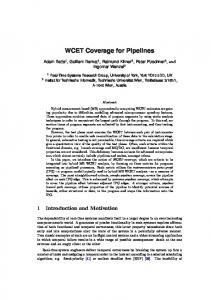
Figure 5: Overview of TMS platform.
We have implemented the proposed methodology in a real multi-core system, i.e. the TMS, to evaluate the behavior of our methodology. The implementation of two main mechanisms highly depends on the target platform: a) the time monitoring of the ongoing execution and b) the suspension/resuming of the low criticality tasks. These two mechanisms are described in Section 4.1. Section 4.2 presents the results under several experimental setups.
4.1
System Implementation
We are targeting a real multi-core COTS platform, i.e. the TMS320C6678 chip of Texas Instrument [16]. The platform is composed of 8 TMS320C66x DSP processors clocked at 1 GHz, which can issue up to 8 instructions in one clock cycle. Each core contains 32 KB level 1 program memory (L1P), 32 KB data memory (L1D), and 512 KB level 2 memory (L2) that may contain instructions and data, which can be configured as cache, SRAM or a hybrid. The level 3 memory (L3) of 4 MB on-chip SRAM and the external DDR3 of 512 MB memory is shared among the cores. The cores and the hardware modules are connected via the TeraNet onchip network. The overview of the system is depicted in Fig. 5. We appropriately configure the TMS and implement the low-level functions to support the timing monitoring and the suspension/restart of the low criticality tasks. The overhead of our controller is: 70 cycles for the time monitoring, 200 cycles for sending an event and 501 cycles for computing the RWCETiso (x) and the safety condition.
4.1.1 Time monitoring We reuse the bare-metal library of [13] that provides a set of timing functions to read the current clock by accessing the control registers TCSL and TCSH of the local core clock, which runs at the core’s frequency. As the system should start the execution when all tasks have been loaded to the cores, this library also provides a synchronization scheme to ensure that cores start at the same time. When an observation point is reached, the run-time control uses the functions to read the real execution time of the system.
4.1.2 Suspension/Restart of low criticality tasks The suspension and the resume of the low criticality tasks
is implemented using the event and interrupt mechanisms of the TMS. The bare-metal library is extended with a set of functions that (1) configure the events and the interrupts of the TMS, (2) allow the use of the events by providing software setting, clearing and monitoring mechanisms for the events, (3) suspend or resume the low criticality tasks. The TMS provides chip level events and core level events. A chip level event is created by the source core by setting the corresponding bit of the event to its Event Flag Register. Then, the Chip-level Interrupt Controller (CIC) is configured to generate host interrupts that act as core event inputs to the DSP interrupt controller of the destination core. The DSP interrupt controller allows up to 124 core events to be routed to the DSP interrupt/exception inputs. Each DSP can receive 12 maskable/configurable interrupts, 1 maskable exception, and 1 unmaskable interrupt/exception. When the DSP interrupt controller receives the core event, sets the corresponding bit to the Interrupt Flag Register of the destination core, an interrupt is generated to the core, the execution of the task is suspended and the Interrupt Handling Routine (IHR) is executed to deal with the interrupt. In our implementation we have placed the master in the core 2, as depicted in Fig. 6, where core 0 and core 1 (gray cores) run critical tasks and the remaining cores run low criticality tasks (white cores). 2
1
Core0
Core2
Core1
Master
3
Coren ... 4
Figure 6: Suspend/restart of low criticality tasks We have configured the TMS to map different chip level events for the synchronization between cores. Each chip level event is sent from a core to a host interrupt and then to a core level event for the corresponding DSP. The core that runs the master is configured to send a chip level event to each core that runs low criticality tasks to suspended their execution. Each core that runs a critical task sends a chip level event to the core that runs the master for the request to isolated execution and to notify that it has finished its execution. Then, we have implemented a core event configuration per DSP which maps each core event to one configurable interrupt. The master requests are handled by IHRS and IHRE and the cores with low criticality tasks by IHRLC . In our example in Fig. 6, in case the safety condition of one of the cores does not hold (e.g. core 1), the low criticality tasks must be suspended. Core 1 sends an interrupt (black arrow 1) to core 2 through node NS to notify that suspension should immediately take place, it turns off its control mechanism and continues the execution of the critical task. When this interrupt is received at core 2, the execution of the low criticality task on core 2 is stopped and the IHRS is executed. The IHRS clears the received interrupt to be able to get the next one and increases the number of interrupts received. If it is the first interrupt received, it sends the interrupts to the remaining cores that run low criticality tasks (black arrow 2) by setting the corresponding bits to Event Flag Register of core 2. Then, it enters an active waiting mode until a new interrupt is received. The core level events are routed to the host interrupt controllers and
finally to the DSP interrupt controllers through the CIC. The corresponding bit to each Interrupt Flag Register is set, the execution of the low criticality task is stopped and the IHRLC is executed to deal with the interrupt. It clears the interrupt to be able to get the next interrupt from the interrupt controller and puts itself in an active waiting mode until a new interrupt is received. In our example of Fig. 6, when the requester for isolated execution finishes (core 1), it sends an interrupt to notify core 2 (e.g. gray arrow 3). When the master in core 2 receives the interrupt, it reduces the number of active requests for isolated execution. If no other critical task has requested isolated execution, it sends the interrupts (e.g. gray arrow 4) to the cores that run low criticality tasks to notify that they can continue their execution and exits the active waiting mode. When the low criticality cores receive such an event, their IHRLC exits the waiting mode and returns to the execution.
4.2.2 Behavior of high criticality tasks Fig. 7 compares the WCETmax in maximum load with 6 low criticality tasks (6LC) in comparison with the WCETiso depending on the application size given by the loop bounds. We observe that the difference between the WCETiso and WCETmax increases when the number of congestions to the shared resources increases. Isolated execution
2000
Experiments
In our experiments we have considered two loop and data dominated critical tasks with similar execution times and deadlines, i.e gemm from Polybench suite [25] which consists of three nested loops with main memory accesses and a set of arithmetic operations. The tasks are sharing the same main memory parts and run on core 0 and core 1. The remaining cores run a set of low criticality loop and data dominated tasks which are accessing different main memory parts. We explore the behavior of our methodology by tuning: 1. the application size of the critical task, which is given by the loop bounds and affects the arrays’ size, the number of memory accesses and the execution time, 2. the number of cores that run low criticality tasks, i.e. from 1 core up to 6 cores, 3. the deadline of the critical tasks DC , i.e. from tight deadlines close to the WCETiso up to more relaxed deadlines, 4. the granularity of the software run-time control mechanism, i.e. the position of the observation points: • coarse-grained : At the head points of level 1 (HP1), • fine-grained : At the head points of levels 1 and 2 (HP2), • very fine-grained : At the head points of all levels (HP3).
1500
1000
500
0 8
16
32
64
128
Loop bounds
Figure 7: WCETs for several loop bounds Fig. 8 depicts the WCETmax for several numbers of low criticality tasks (2 in which case WCETmax = WCETiso up to 8 parallel tasks) for an application size equal to 32. We observe that the WCET highly depends on the number of tasks that run in parallel. The WCET difference between isolated execution and maximum load with 6 low criticality tasks has a factor of 6.28. 80 70
4.2.1 Design-time analysis
60
WCET(ms)
Although we have configured our system to be supported by static WCET analysis, no static WCET analysis tool, such as Ait or Otawa [28], is available for the TMS320C6678 platform. As it is not the scope of this paper to extend the supported platforms for static analysis tools, we use a measure-based approach by using the local timer of the cores that run the critical tasks to compute the timing information of the critical tasks, i.e. the d(x), the w(x) and the Wmax for each critical task. The d(x) and the w(x) are measured when the critical tasks are the only tasks executed on the system and for each observation point of a critical task. To reduce the overhead introduced by our run-time measurements, we perform the timing measurements by considering one point per execution. For the computation of the d(x), we use the maximum time observed between the head point and the point x. For the computation of the w(x), we use the maximum time observed between any two consecutive iterations of the loop. The Wmax is measured when the critical tasks run in maximum load for each different number of low criticality tasks and for each position of observation points. The computation of the Wmax is performed by read-
Max load (6LC)
2500
WCET(ms)
4.2
ing the local clock, subtracting any two subsequent observed times and using the maximum time difference. The maximum time overhead of our run-time control for reading the local timer is 70ns, for the RWCETiso (x) computation and the safety condition is 501ns and for the request and suspension/resume of the low criticality tasks is 200ns.
50 40 30 20 10 0 2
3
4
5
6
7
8
Number of parallel tasks
Figure 8: WCET for several parallel tasks Fig. 9 illustrates the execution time of the critical tasks τC1 and τC2 for several deadlines and granularities for an application size equal to 32. We observe that the suspension of the low criticality tasks occurs: • For the HP1 configuration: 1) relatively quickly, when the deadlines are tight (e.g. < 14.00ms). The observation points are far away one from the other, the w1 is quite
gain obtained by the methodology is:
NoInstr HP1 HP2 HP3
(t − tiso )/tiso
25.5
3.5
HP1 HP2 HP3
3
20.5
2.5 15.5
Gain
τC1, τC2 Exec.Time (ms)
30.5
10.5
2 1.5 1
12.5
15
17.5
20
22.5
25
27.5
30
32.5
35
37.5
40
42.5
45
47.5
50
Critical Deadline (ms)
0.5 0
Figure 9: Exec.time of τC1 & τC2 for several deadlines 50
.5 12
15 17.5
20 22.5
25 27.5
30 32.5
35 37.5
40 42.5
45 47.5
50
Critical Deadline (ms)
NoInstr HP1 HP2 HP3
(a)
40
τ1 Exec. Time (ms)
6 HP1 HP2 HP3
5
30
4
Gain
20
3
10
2
0
1 12.5
15
17.5
20
22.5
25
27.5
30
32.5
35
37.5
40
42.5
45
47.5
50
Critical Deadline (ms) 0
Figure 10: Execution time of τ1 for several deadlines
8.2 28.6 62 6
9 62
0 64
0 66
0 68
0 70
0 72
0 74
0 76
0 78
0 80
0 90
00 11
00 13
00 15
00 30
Critical Deadline (ms)
(b) large and thus the safety condition is early violated, and 2) never, when the deadline is relaxed. For instance, for deadlines > 14.00ms, the execution time of τC1 and τC2 is stable, as it has been completely executed maximum load scenario. • For the HP2 and HP3 configuration: 1) quickly but later that HP1, when the deadlines are tight, as the lower granularities allow the exploration of the task suspension in smaller steps, 2) never, when the deadline is quite large. For these smaller granularities, the deadline in which the system is always executed in maximum load has a larger value that HP1 configuration, i.e. 30.00ms for HP2 and 45.00ms for HP3, and 3) in between otherwise.
4.2.3 Gain on resources utilization We explore the gains of our method by tuning (1) the deadline of the critical task and the (2) granularity of the observation points of our software controller. Fig. 10 illustrates the execution time of the low criticality task τ1 for several deadlines and granularities for an application size equal to 32. We observe that the more time the critical task spends in the maximum load, the longer are the execution times of the low criticality tasks. To explore the gain of our methodology, we consider the following notion: Definition 7 (Relative gain). Let t denote the execution time of the low criticality task with our methodology and tiso the execution time in isolation mode. The relative
Figure 11: Gain for several deadlines with application size a) 32 and b) 128 Fig. 11(a) presents the behavior of the relative gain of our approach with the HP1, HP2 and HP3 configuration with respect to the different deadlines for an application size equal to 32. From the experiments, we observe that our approach achieves significant relative gains: • For the more relaxed deadlines (still below the RWCETmax i.e. 18.50ms), e.g. in 15.5ms, we have the highest gain of 2.9885 or 298.85 % for HP1. The HP1 configuration provides the largest gain. It calls the run-time controller in larger steps, and the slack time, i.e. the time between the critical task’s end and the deadline, is quite short. • For larger deadlines, we still have a gain which is decreasing when the deadline is further relaxed. • For tight deadlines, e.g.