Sep 5, 1993 - Hans Müller(2), Ernesto Perea(4), Bernhard Skaali(1). (1) Department of Physics, University of Oslo, Norway. (2) CERN, 1211 Geneva 23, ...
September 5, 1993 6:17 pm Distributed SCI-based Data Acquisition Systems constructed from SCI bridges and SCI switches
Distributed SCI-based Data Acquisition Systems constructed from SCI bridges and SCI switches Bin Wu(1), Andre Bogaerts(2), Roberto Divia(2), Ernst Kristiansen(1)(3), Hans Müller(2), Ernesto Perea(4), Bernhard Skaali(1) (1) Department of Physics, University of Oslo, Norway (2) CERN, 1211 Geneva 23, Switzerland (3) SINTEF SI, Oslo, Norway (4) Thomson CSF, Orsay, France
ABSTRACT The new standard IEEE std. 1596-1992, Scalable Coherence Interface (SCI)-- provides novel possibilities to build data acquisition systems for large and very high rate experiments in High Energy Physics (HEP). The RD24 project at CERN started 2 years ago to investigate applications of SCI to data acquisition at the Large Hadron Collider (LHC). The participants come from CERN, universities and computer companies. As part of the RD24 project, simulation of large SCI-based data acquisition systems is performed by a simulator written in the object-oriented language MODSIM II. A typical ring structure is sensitive to hardware failures and limited by its peak load. Early simulations showed that large SCI rings are not scalable. An SCI bridge model, which is in principle two SCI node chips connected back-to-back, is presented here and used as a building block for a simulated system. Several rings connected by SCI bridges can offer high performance, but large SCI-based systems containing thousands of nodes with many bridges will not be able to utilize the potential bandwidth. A long path between nodes leading through bridges also introduces long latencies. We present an SCI switch model, which provides a direct connection between any two rings that are connected to the switch. Such an SCI switch will significantly improve system performance and give a lower latency. We compare the simulation results and show the differences between SCI systems based on pure SCI switches and those based on SCI bridges, in particular the different performances and latencies under various load and design parameters such as the depth of input/output FIFOs, switch (bridge) delays etc. We investigate self-routing SCI multistage DAQ systems with optimized configuration, which is uniquely routed. The goal of this paper is to investigate the difference between SCI switch- and SCI bridge-based systems, and to study some of the design criteria for the SCI switch element to form the interconnection of large scale SCI-based data acquisition systems.
1. Introduction The approved IEEE Std 1596-1992 Scalable Coherent Interface (SCI) [Gust-92][SCI-92] provides the services one expects from a computer bus, but avoids the limitations of buses by using point-to-point links and a packetbased, split response protocol. With differential ECL signals, the standard specifies a transfer rate of 1 Gbyte/s per link. The name Scalable Coherent Interface (SCI) defines what SCI is. Scalability provides the possibility that the same mechanism can be used independently of the number of nodes, in other words, up to 64K nodes can be connected together; Coherence supports the efficient use of cache memories in the most general and easiest-touse multiprocessor model; Interface means that products from multiple vendors can be incorporated into one system and inter-operate smoothly. Page 1
Distributed SCI-based Data Acquisition Systems constructed from SCI bridges and SCI switches
SCI-based systems can contain up to 64K nodes, and can be interconnected to implement the architecture which is best suited for a specific application. Ring-based systems are already being implemented, however, an SCI-SCI switch needs to be developed for constructing large system. Large scale data acquisition systems may be a field where SCI can have a profound impact. The data acquisition system (DAQ) for the proposed Large Hadron Collider (LHC) at CERN represents an enormous challenge for designers and implementors. The estimated number of electronics channels and the bandwidth required are several orders of magnitude larger than found in current systems. New concepts as well as new technology will be required in order to build such a system. Currently a research program at CERN, RD24 [RD24-93] investigates the use of SCI as a very high speed interconnect for LHC experiments. The R & D projects at CERN are projects that have been approved by the “Detector Research & Development Committee”. The participants of RD24 are groups from CERN, University of Oslo, INFN (Rome), University of Rome, IHEP (Moscow), and the companies Dolphin SCI Technology (Oslo), Digital Equipment Corporation, CES (Geneva), Apple Computer Inc., IFIC (Spain) and Thomson-CSF (France). As a first SCI application [Mull-93], RD24 started the design and test of single-ring components, i.e. processor and memory nodes. A ring is known for its simple characteristics and based on a two-link connection, where the output signals from one module are fed to the input signals of the next. On the other hand, a ring is always limited by the long path the packet should pass and will not behave well when there is more than 15 links of nodes [ScGV-92]. Connecting several rings can improve performance and give a lower latency, so in its second phase, RD24 plans to extend to multiple rings and ultimately, to large SCI systems. However, in order to connect every two rings, an SCI ring-to-ring bridge will be needed. Ultimately SCI switches are a definite long term need to interconnect a large number of nodes together in an effective way. In the next section we will present an SCI bridge model which is in principle two SCI node chips connected back-to-back, and further an SCI switch model, which provides a direct connection between any two rings that are connected to the switch. We will also analyze the differences between these two models. In section 3, we will look into a multistage network system, a potential candidate for DAQ systems. In section 4, we will present the simulation results and show the difference between SCI multistage DAQ systems based on pure SCI switches and those based on SCI bridges, in particular the performances and latencies under various loads and design parameters such as depth of input/output FIFOs, switch delays etc. We will summarize and draw our conclusions in section 5.
2. SCI bridge and SCI switch An SCI switch (bridge) is a key component in building up large SCI-based processor architectures. The SCI standard [SCI-92] does not directly specify an SCI switch or bridge. A wide variety of interconnection mechanisms is possible.
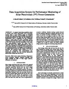
2.1 SCI bridge The SCI specification [SCI-92] proposes several different topologies that can be built up with simple ring-to-ring bridges. These SCI bridges have two inputs and two outputs as shown in Figure 1.a. Data will go unidirectionally into the inputs and come out from the outputs. The inputs and outputs here are 16-bit wide data. By means of SCI bridges, one can connect 2 rings, 3 rings or even more rings together (Figure 1.b, 1.c, 1.d). The ways of connection are very flexible with many trade-offs of performance and latency. A detailed block diagram of the SCI bridge is shown in Figure 2. Two SCI node chip compatible ports are connected back-to-back. K-ary N-cube structured systems based on such bridges are extensively studied [BoHu91][BoHu-93][KrBH-92]. Using SCI bridges, one can connect SCI rings together to form a multi-processor SCI system that can by far overcome any bus systems existing now. Simulation of multiple rings connected by SCI bridges was presented as early as 1991 in [BDMR-92]. Page 2
Distributed SCI-based Data Acquisition Systems constructed from SCI bridges and SCI switches
(a)
(b)
(c)
(d)
SCI node or SCI bridge connected to another SCI ring FIGURE 1. (a) A block diagram of SCI bridge, (b) 2 rings connected by an SCI bridge, (c) 3 rings connected by 2 bridges, (d) 4 rings connected by 4 bridges
Link 1 In
Link 1 Out AD
RT
bypass-FIFO
req res
req res
Link 2 In
AD
RT
MUX
bypass-FIFO
Link 2 Out
MUX
Echo Packet path
AD: Address Decoder;
RT: Routing Table;
Mux: Multiplexer;
req: request FIFO;
res: response FIFO
FIGURE 2. A model of SCI bridge
Page 3
Distributed SCI-based Data Acquisition Systems constructed from SCI bridges and SCI switches
An SCI bridge is a special case of an SCI switch. It is a 2-switch by our definition of N-switch1. The name “SCI bridge” is conventional since its original purpose is to connect two SCI rings.
2.2 SCI switch module In high rate DAQ systems, a need to maximize total throughput of the system and minimize the mean end-toend packet delay across the SCI system could make SCI bridge an inappropriate choice. An SCI switch model is presented in this section. In an SCI switch, hardware complexity is traded for increased bandwidth and decreased latency. The SCI switch model presented here is a general model. It emphasizes several of the most important features of SCI switch properties, namely scalability, simplicity and high speed. Concerning scalability, the SCI switch is a model that is suitable for any size of a network; its structure is expandable to connect any size of rings; an SCI N-switch will be made of N node chip compatible ports with crossbar connectivity among these ports. As for simplicity, the SCI switch model inherits most of the features from SCI and the existing SCI node chip to enhance its performance at low latency and complexity. Finally high speed, it is capable of 1 Gbyte/s per link. For an N-switch, it is therefore theoretically possible to provide a performance of N Gbyte/s in input links and N Gbyte/s in output links. A simplified block diagram of a 4-switch is shown in Figure 3.
SCI ring 1
SCI Node Compatible SCI switch Port 1
SCI Node Compatible SCI switch Port 2
SCI ring 2
CROSSBAR CONNECTION
SCI ring 4
SCI Node Compatible SCI switch Port 4
SCI Node Compatible SCI switch Port 3
SCI ring 3
unidirectional interconnections
In the figure, the number of nodes per ring varies.
SCI node or SCIswitch element
FIGURE 3. Block Diagram of 4-switch
1. An N-switch is an SCI switch with N-pair SCI input/output links, and crossbar interconnection in between.
Page 4
Distributed SCI-based Data Acquisition Systems constructed from SCI bridges and SCI switches
The 4-switch consists of 4 SCI node compatible ports. The details inside each port are described in Figure 4. The crossbar connections between the ports are unidirectional links that run at SCI speed or lower speed in order to reduce the costs. Each port has a routing algorithm that supports a fast decision algorithm based on routing information, for instance, the address in the incoming packet. If the incoming packet does not route locally, i.e. not to a node on the same ring, a logic will check whether the corresponding output-FIFO is free or not. If the FIFO is free, the packet is accepted and stored in the output-FIFO, and an echo will be sent back to the request node, otherwise a retry-echo will be sent. The checking of an output-FIFO may be slow, so different techniques can be used. One method is to put a “score-board” near the routing logic to indicate if the output-FIFOs are free or not. A “score-board” is scored once the output-FIFO is busy, and it is freed when the output-FIFO is free. One single bit per output-FIFO (on the far side of the same switch) and a single connection can be used to implement it. Thus the FIFOs in a switch may behave exactly as FIFOs in a normal node chip at SCI speed. Separate request and response FIFOs are needed to avoid deadlock [SCI-92].
Routing Table
SCI LINK IN
Address Decoder
output-FIFO,req
CSR
output-FIFO,resp
To other N-1 ports’ output FIFOs on the same switch
echo
Free Checking
SCI Bypass FIFO
MUX SCI LINK OUT
FIGURE 4. One of the N ports of an N-switch
2.3 SCI switches built of SCI bridges (2-switch) Today’s technology may restrict temporarily the switch multiplicity to N= 2. Figure 5.b shows a possible way to build a 4-switch based on four SCI bridges. We can use the same concept to build large SCI switches, but as we mentioned before, connecting more nodes on an SCI ring will result in a big penalty in performance. In this paper we will only consider the situation of the 4-switch. We call the crossbar-like switch in Figure 5.a a pure 4-switch, and the one in Figure 5.b a bridge-based 4-switch. Using SCI bridges to build SCI switches is an alternative to using pure SCI switch for large-scale SCI systems. We will theoretically compare both systems and then quantify their difference by simulations. In this paper, we call the systems interconnected with those two 4-switch forms a pure 4-switch-based system and an SCI bridge-based system respectively.
2.4 Pure SCI switch versus SCI bridge-based switch In Figure 5.b the internal ring of each switch element consists of 4 SCI bridge ports. The internal ring’s throughput will be confined by congestion. The latency will be more than two times longer than using the pure SCI switch. We list some points for comparison of these two kinds of switches in Table 1. The routing is
Page 5
Distributed SCI-based Data Acquisition Systems constructed from SCI bridges and SCI switches
(b)
(a)
FIGURE 5. (a) A pure SCI 4-switch; (b) 4-switch built of 4 SCI bridges.
assumed to be distributed on each SCI port.
Table 1: Comparison of different 4-switches Type of 4-switch
SCI bridge-based switch a
pure SCI switch
Max. bandwidth (Gbyte/s)
2.5
4
Min. average latencya
1.5 Bridge Delays+1 Bypass Delay
1 Switch Delay (can be equivalent to 1 Bridge Delay)
# of node compatible ports
8
4
# of routing logic
8
4
Complexity of routing logic
level x
level x
# of input FIFOsb
0
0
# of output FIFOs
8
4
# of bypass FIFOs
8
4
Total # of FIFOs
16
8
Self routing possibility
easy
easy
Additional logic apart from SCI nodechip
a little
some
Complexity in internal connection
easy
difficult
relatively easy
difficult
c
All in single module
a. each active node sends packets randomly to others b. request and response FIFOs are referred together c. including multichip module
3. Multistage network and SCI switches Conventional knxkn multistage networks have kn inputs connected to kn outputs through n stages of k2 switches. SCI is a new protocol that is based on packet transmissions. In SCI, the point-to-point links are unidirectional. The return path must be provided for the acknowledge packets. This makes the ring structure a basic choice for SCI systems. Figure 6 is an example multistage system using SCI. We found that we must
Page 6
Distributed SCI-based Data Acquisition Systems constructed from SCI bridges and SCI switches
4-switch
4-switch
4-switch
4-switch
4-switch
4-switch
4-switch
4-switch
4-switch
4-switch
4-switch
producers
4-switch
consumers
develop a new terminology to conform with the new system. Instead of calling it 8x8 or 16x16 which neither of them are exactly, we call it an 8Rx8R multistage system. This system is suitable for data acquisition systems, where normally memories (producers) sit on one side and processors (consumers) on the other. The 4-switch (2Rx2R switch1) in the figure could be a pure 4-switch as shown in Figure 5.a, or a switch that is based on SCI bridges in Figure 5.b. Our simulations will be based on this figure.
SCI node, could be many FIGURE 6. 8Rx8R DAQ system (baseline) interconnected by 4-switches One of the main reasons we choose a multistage interconnection network as our system model is its suitability for self-routing [WuFe-80]. Self-routing, also called digitally controlled routing, is characterized by its high speed (small routing latency), simple and well suited for chip design. The key property of the self-routing algorithm is that for a packet to route through a network, each address decoder operates independently of all others upon information at the target address at the start of the packet [Wu-93]. The multistage system in Figure 6 is an optimized configuration, which is uniquely routed if we guarantee the forwarding of packets in stages. The number of 4-switches being used is minimized and the routing algorithm becomes simple, but this also restricts the possibility of alternative routing. The simulations of a 8Rx8R multistage DAQ system can to a great extent reflect the behaviors of larger systems. We have done simulations on a 64Rx64R DAQ system2 [RD24-93], and the result is similar to the simulations we present in this paper.
1. A 4-switch is also called 2Rx2R (2-ring by 2-ring). It is different from nxn, which is unidirectional. The small R in the subscript indicates the links are bidirectional, more precisely, are rings. 2. Simulations of a 64Rx64R DAQ system normally run for weeks on a SUN SPARC 10.
Page 7
Distributed SCI-based Data Acquisition Systems constructed from SCI bridges and SCI switches
4. Simulation 4.1 Simulation tools and simulator MODSIM II [CACI-91] is an object-oriented, discrete-event simulation language from CACI Products Company, La Jolla, Ca. It was selected for modeling the low level SCI protocols that govern the exchange of packets between SCI nodes. The object-oriented approach leads to great advantages since new modules can inherit most properties from existing ones and thus one can construct large systems easily. Discrete-event simulation allows description of a system in terms of logical relationships which cause changes of state at discrete points in time. An example: an SCI packet arrives and changes the state of the FIFO instantaneously. SCILab [BoWu-93], a set of SCI modeling tools was developed to simulate the data flow of distributed SCI systems. A time resolution down to SCI packet size with flow control (~100ns on average) allows accurate simulation of congested data pathways. There are also provisions for building SCI networks consisting of rings interconnected by bridges or switches. Various scripts based on standard UNIX tools have been used to prepare the input and output data. A special purpose preprocessor which generates very large multistage network configurations for simulation is also available in C code. The executable code was generated on desktop workstations. For cache coherence, the C-code produced by the IEEE [SCI-92] has been linked into the MODSIM code. It is possible to set many parameters in our SCI simulation. Several of the most important parameters and our choices of the values in the simulation are listed below. All the results we present in this paper are based on the simulations of multistage DAQ system architecture.
Table 2: Simulation Parameters for an SCI System Parameter
Our choice of value
Simulation Time: The length of simulation
500000 ns
Reset Time: The time to reset all statistics counters, used to eliminate start-up effects.
100000 ns
Number of nodes in system: no limit
1-unlimited
Node Type: memory / definite target packet generator / random target packet generator
memories on one side and random generators on the other
Packet Type: any type of SCI packets, e.g., dmove64, nwrite16, etc.
dmove64
in/out FIFO depth for SCI node, i.e number of outstanding request/response packets: in units of SCI packets, no limit
1-16 3 if not specified
in/out FIFO depth for SCI switch element, i.e number of outstanding request/response packets: in units of SCI packets, no limit
1-16 3 if not specified
Request/Response Delay: the time for a processor to process a request/response packet
50 ns
The interval between 2 successive packets generated by a processor, this parameter reflects the CPU speed, cache hit ratio, and is used to adjust the load on the system.
50 ns
Bypass Delay: due to link delays, connectors, and the time needed for a packet to bypass an idle node, etc.
15 ns
Switch Delay: the time an SCI switch needs for address decoding, routing-table checking, etc., we assume that the Bridge Delay is of the same value as Switch Delay
25 ns if not specified
Page 8
Distributed SCI-based Data Acquisition Systems constructed from SCI bridges and SCI switches
4.2 Simulation Results In [RD24-93] we have already shown that a multistage DAQ system scales well when the size of system increases. The optimized depth of FIFOs to get best performance is also indicated in that report. Here we give more details, and show more results. The terminologies used in the figures are: Raw Throughput is the total bandwidth of packets that the producers send to the consumers. Net Throughput represents only the data bandwidth. Retry Throughput is the total retry bandwidth in the whole system, including the retries between middle stages. Latency (Transaction Duration) is measured from the entry of a request packet in its output FIFO until the response packet comes back. For responseless packets such as dmove64, it is the duration from the request packet in its output FIFO until it is in its target’s input FIFO. 4.2.1 Throughput and latency in multistage networks Figure 7.a, b give us a proof of scalability of pure 4-switch-based system as well as bridge-based system. We did simulations on 2Rx2R (e.g., 4-switch itself), 4Rx4R, 8Rx8R, 16Rx16R, 32Rx32R, 64Rx64R multistage networks, and found the throughput scales well. Net throughput is around 80% of raw throughput, which is quite obvious for dmove64 packets (with 64 of the 80 bytes is data). Simulations of pure 4-switch-based systems
Simulations of SCI bridge-based systems
40
40 dmove64
dmove64 35
The depth of the FIFO for each node is three
30
Throughput (Gigabytes/second)
Throughput (Gigabytes/second)
35
Raw Throughput 25
20 Net Throughput 15
10
5
The depth of the FIFO for each node is three
30
25
20 Raw Throughput 15 Net Throughput 10
5
0 0
10
20 30 40 50 N-ring by N-ring multistage DAQ system, N
60
0 0
10
20 30 40 50 N-ring by N-ring multistage DAQ system, N
60
FIGURE 7. a, b. Test of throughput scalability of pure 4-switch-based system and bridgebased system. Latency is a crucial parameter which needs to be minimized. In our simulation, the latency doesn’t increase proportionally with the size of the DAQ system (Figure 8.a,b). This is due to the number of stages in multistage network does not increase proportionally with the size of the system. The latency of pure 4-switchbased system is much more lower than bridge-based system. This is because there are much more retries in the later system and longer path each packet has to travel.
Page 9
Distributed SCI-based Data Acquisition Systems constructed from SCI bridges and SCI switches
Simulations of pure 4-switch-based systems
Simulations of SCI bridge-based systems
3500
3500 dmove64
dmove64 The depth of the FIFO for each node is three
The depth of the FIFO for each node is three
3000
3000
2500
2500 Average Latency (ns)
Average Latency (ns)
Transaction Duration
2000
1500 Transaction Duration
2000
1500
1000
1000
500
500
0 0
10
20 30 40 50 N-ring by N-ring multistage DAQ system, N
0 0
60
10
20 30 40 50 N-ring by N-ring multistage DAQ system, N
60
FIGURE 8. a, b. Latency of pure 4-switch-based system and bridge-based system. 4.2.2 Throughput and latency versus depth of FIFOs1 In [RD24-93] the optimized FIFO depth for a switch port is ca. 3 longest SCI packets. Figure 9.a and Figure 10.a demonstrate that result again, both from throughput and latency evaluations. A three longest-SCI-packetsdeep FIFO is probably the most cost effective choice for a pure-switch-based system with the simulation parameters specified. Figure 9.b and Figure 10.b. indicate that two-packet-deep-FIFO is also a reasonable choice for an SCI bridge-based system. In Figure 10.b, the latency increases when deeper FIFOs are used. It is Simulations of pure 4-switch-based systems
Simulations of SCI bridge-based systems
12
12 dmove64
dmove64
The depth of the FIFO for each active node is three
The depth of the FIFO for each active node is three 10 Throughput (Gigabytes/second)
Throughput (Gigabytes/second)
10
8 Raw Throughput 6
Net Throughput
4
2
8
6
Retry Throughput
4
Raw Throughput
2
Net Throughput
Retry Throughput 0 0
2
4
6 8 10 12 Depth of output FIFOs in 4-switches
14
16
0 0
2
4
6 8 10 12 Depth of output FIFOs in SCI bridges
14
16
FIGURE 9. a, b. Finding the optimized depth of FIFOs, throughput evaluation, pure 4-switchbased system versus bridge-based system, 8Rx8R multistage DAQ systems. because the deeper the FIFOs are, the more possibility that packets will be blocked in the middle stages in the network due to retries. On the contrary, the curve in Figure10.a is flat when deeper FIFOs are used. It is because of less retries (refer to Figure 9, retry throughput). Too many retries is also the reason that makes oneFIFO system has longer latency than two-FIFO system in Figure 10.b.
1. The depth of FIFO is the same as the number of allowed outstanding requests.
Page 10
Distributed SCI-based Data Acquisition Systems constructed from SCI bridges and SCI switches
Simulations of SCI bridge-based systems
Simulations of pure 4-switch-based systems 6000
6000
dmove64
dmove64 5000
4000
Average Latency (ns)
Average Latency (ns)
The depth of the FIFO for each active node is three
The depth of the FIFO for each active node is three
5000
3000
2000
1000
0 0
4
6 8 10 12 Depth of output FIFOs in 4-switches
Transaction Duration 3000
2000
1000
Transaction Duration
2
4000
14
0 0
16
2
4
6 8 10 12 Depth of output FIFOs in SCI bridges
14
16
FIGURE 10. a, b. Finding the optimized depth of FIFOs, latency evaluation, pure 4-switchbased system versus bridge-based system, 8Rx8R multistage DAQ systems.
One of the interesting tests is to see how a one-FIFO-node system behaves. From Figure 11.a,b we can see that for a heavily loaded system where the interval between two successive packets is less than 500 ns, a one-FIFOnode system has a worse performance than a three-FIFO-node system. This is due to the characteristics of SCI, i.e. packet transmissions must be acknowledged by echo packet. The send packet will stay in the “only” FIFO until it receives an echo confirming that the transmission has succeeded. Figure 12.a,b shows that the latency of a one-FIFO-node system is also longer compared with a three-FIFO-node system. The heavier the load the much difference the performance is. Simulations of SCI bridge-based systems
Simulations of pure 4-switch-based systems
10
6
dmove64 The depth of the FIFO for each node is three solid line: One-FIFO-node system;
Throughput (Gigabytes/second)
Raw Throughput
8
dashed line: Three-FIFO-node system.
Retry Throughput
solid line: One-FIFO-node system; dashed line: Three-FIFO-node system.
Throughput (Gigabytes/second)
5
dmove64 The depth of the FIFO for each node is three
9
4 Retry Throughput 3
2 Raw Throughput
7 6 5
Retry Throughput
4 3
Raw Throughput
2 1
1 Raw Throughput Retry Throughput 0 0
100 200 300 400 500 600 The interval between two successive packets being generated (ns)
700
0 0
100 200 300 400 500 600 700 800 900 The interval between two successive packets being generated (ns)
1000
FIGURE 11. Throughput for both pure-switch-based system and bridge-based systems when the depth of FIFO is one. 8Rx8R multistage DAQ systems.
For a lightly loaded system where the interval between two successive packets is larger than 500 ns, using deeper FIFOs will not increase performance for a three-FIFO-node system. From Figure 11 and 12, we can also find that the load of the system can affect the performance too. Generally
Page 11
Distributed SCI-based Data Acquisition Systems constructed from SCI bridges and SCI switches
speaking, higher throughput is achieved by saturating the system with packets, at the expense of longer latency. Simulations of pure 4-switch-based systems
Simulations of SCI bridge-based systems
600
2200 solid line: One-FIFO-node system; dashed line: Three-FIFO-node system.
2000 500
dmove64
400
Average Latency (ns)
Average Latency (ns)
1800
Transaction Duration 300
200
The depth of the FIFO for each node is three
1600 1400 1200 1000
solid line: One-FIFO-node system; dashed line: Three-FIFO-node system.
800
dmove64
600
Transaction Duration
100 The depth of the FIFO for each node is three 0 0
100 200 300 400 500 600 The interval between two successive packets being generated (ns)
400 0
700
100 200 300 400 500 600 700 800 900 The interval between two successive packets being generated (ns)
1000
FIGURE 12. Latency for pure-switch-based system and bridge-based system when the depth of FIFO is one (compared with three). 8Rx8R multistage DAQ systems.
4.2.3 Switch delay All the simulations we have done so far are based on one assumption: the SCI switch internal interconnections Simulations of pure 4-switch-based systems 12
solid line: switch delay = 250 ns; dashed line: switch delay = 25 ns;
dmove64 The depth of the FIFO for each active node is three
dmove64 The depth of the FIFO for each active node is three
10 Throughput (Gigabytes/second)
10 Throughput (Gigabytes/second)
Simulations of SCI bridge-based systems 12
solid line: switch delay = 250 ns; dashed line: switch delay = 25 ns;
8 Raw Throughput 6
4
8
6
Retry Throughput
4 Raw Throughput
2
2 Retry Throughput
0 0
2
4
6 8 10 12 Depth of output FIFOs in 4-switches
14
16
0 0
2
4
6 8 10 12 Depth of output FIFOs in 4-switches
14
16
FIGURE 13. Using long switch delay will affect the throughput on a pure-switch-based system more than a bridge-based system, 8Rx8R multistage DAQ systems. are running at SCI speed, with 16-bit wide data paths. This assumption is reflected in that we specify switch delay as 25 ns. If we take today’s technology to handle skew and other hardware effects into consideration, we may only achieve 250 ns. Then the performance and latency of the systems we have simulated will be different. We reran some of the simulations, and we found that both systems decrease their performance to some extent (see Figure 13, 14), but the bridge-based systems are less affected. This is because the switch delay which has more influence on a pure-switch-based system than on a bridge-based system, where the
Page 12
Distributed SCI-based Data Acquisition Systems constructed from SCI bridges and SCI switches
internal ring structure also plays a heavy role in addition to switch delay. The bypass time is still 15 ns for a 500 MHz GaAs node chip. This leaves the latency caused by the bridges on internal rings unaffected. Longer switch delay results much lower throughput for those systems with depth of FIFOs is less than 8. The overall latency is longer. This makes the choice of optimized depth of FIFOs towards deeper FIFOs, such as 68 for pure-switch-based systems and 3-5 for bridge-based systems Simulations of pure 4-switch-based systems
Simulations of SCI bridge-based systems 7000
6000
solid line: switch delay = 250 ns; dashed line: switch delay = 25 ns;
6000
5000
dmove64 The depth of the FIFO for each active node is three
5000 Average Latency (ns)
Average Latency (ns)
7000
4000
3000
3000
2000
1000
1000
2
4
6 8 10 12 Depth of output FIFOs in 4-switches
14
16
dmove64 The depth of the FIFO for each active node is three
4000
2000
0 0
solid line: switch delay = 250 ns; dashed line: switch delay = 25 ns;
0 0
2
4
6 8 10 12 Depth of output FIFOs in SCI-bridges
14
16
FIGURE 14. Using long switch delay will affect the latency of a pure-switch-based system more than a bridge-based system, 8Rx8R multistage DAQ systems.
5. Conclusions SCI switch-based network systems is a new field that needs great attention and effort. In general, one must try to find the trade-offs to achieve the best solutions based on the requirements of performance, latency, cost, etc. An SCI bridge model is actually a conventional 2x2 switch element1. It is simple and easy to build, but does have high performance. Based on experience from the Dolphin NodeChip, this kind of “two node chips back-to-back” interconnection chip will not be too difficult to build. Minimal changes will be required to the node chip. The SCI bridges can be interconnected to form an advanced SCI system, but a system based on SCI bridges will not be able to provide the full potential bandwidth. A more complicated switch element SCI switch is presented. It is simple, scalable, and performs at high speed. We described a modified multistage data acquisition system for implementation in SCI. It is simple and can achieve a relatively high bandwidth and low latency. The simulation in this paper is performed by a MODSIM simulator. From the simulation, we found that, •
The bridge-based system will behave almost the same as the pure switch system except for overall differences in performance and latency.
•
The rules which apply to a pure switches on choosing the optimized depth of FIFO, load condition, to get high throughput and low latency are almost the same for a switch built from SCI bridge.
1. We note again that our new terminology is different from the conventional one.
Page 13
Distributed SCI-based Data Acquisition Systems constructed from SCI bridges and SCI switches
•
The optimized depth of FIFO will be of 2-4 longest SCI packets when there is quite a heavy load on the system. The pure switch-based system will require a little deeper FIFOs than bridge-based system to get a best performance/cost trade-offs.
•
A one-FIFO system will have bad performance. However, with a lightly loaded systems, one-FIFO switches will yield the same result as multiple-FIFO switches. This is true for both systems.
•
Longer switch delay will lower the systems performance. The pure-switch-based system is more sensitive to longer switch delay than bridge-based system. For both systems, deeper FIFOs are required if we want to get the same throughput as the systems with short switch delay.
Adjusting some parameters to increase performance and to reduce cost still need to be done and verified with detailed computer simulations. Other topologies still need to be investigated.
6. Acknowledgment The authors would like to thank Stein Gjessing, Gran Larsen, Eivind Rongved, Knut Ælnes and Håkon Bugge for ideas and discussions that assisted this work. We are also indebted to David Gustavsen for his careful scrutiny of this paper and invaluable suggestions.
7. References [BCVZ-89] R. Brun, O. Couet, C. Vandoni, P. Zanarini, “PAW - Physical Analysis Workstation, The Complete Reference, Version 1.07, CERN Geneva, Switzerland, Oct. 1989 [BDMR-92] A. Bogaerts, R. Divia, H. Muller, J.F. Renardy, “SCI based Data Acquisition Architectures”, IEEE Transactions on Nuclear Science, Vol. 39, No. 2, April 1992 [BoHu-93] J.W. Bothner and T.I. Hulaas, “Topologies for SCI-based systems with up to a few hundred nodes”, Thesis for the degree Candidatus Scientiarum, Institute of Informatics, University of Oslo, Norway, 1993 [BoHu-91] J.W. Bothner and T.I. Hulaas, “Various interconnects for SCI-based system”, Proceedings of Open Bus Systems’91, Paris, pp. 197-202, 1991 [BoWu-93] A. Bogaerts and B. Wu, “The SCILab Cook Book”, internal note, CERN Geneva, Switzerland, July, 1993 [CACI-91] CACI Products Company, “MODSIM II, The Language for Object-Oriented Programming”, Reference Manual, User’s Manual, Tutorial, CACI Products Company, La Jolla, CA 92037 [Gust-92] D.B. Gustavson, “The Scalable Coherent Interface and related Standards Projects”, IEEE Micro, February 1992, pp. 10-22 [Müll-93] H. Müller, et al, “First Experience with the Scalable Coherent Interface”, 8th Conference on RealTime Computer Applications in Nuclear, Particle and Plasma Physics, Vancouver, Canada, June, 1993 [KrBH-92] E.H. Kristiansen, J.W. Bothner and T.I. Hulaas, “Behavior of Scalable Coherent Interface in Larger Systems”, Proceedings CAMAC-92, Warsaw, 29 September 1992 [Kris-93] E.H. Kristiansen, J.W. Bothner and T.I. Hulaas, E. Rongved, B. Skaali, “Simulations with SCI as a data carrier in data acquisistion systems”, 8th Conference on Real-Time Computer Applications in Nuclear, Particle and Plasma Physics, Vancouver, Canada, June, 1993
Page 14
Distributed SCI-based Data Acquisition Systems constructed from SCI bridges and SCI switches
[RD24-93] RD24 project participants, “RD24 Status Report, Application of the Scalable Coherent Interface to Data Acquisition at LHC”, CERN/DRDC 93-20, RD24 status Report, 5. May 1993 [ScGV-92] S.L. Scott, J.R. Goodman, M.K. Vernon, “Performance of the SCI Ring”, Proceedings IEEE ISCA 92, Queensland, May 1992 [SCI-92] IEEE Std.1596-1992, “Scalable Coherent Interface” [WuFe-80] C. Wu and T. Feng, “On a Class of Multistage Interconnection Networks”, IEEE Trans. Computers, Vol. C-29, No. 8, Aug.1980, pp. 694-702 [Wu-93] B. Wu, A.Bogaerts, R. Divia, E. Kristiansen, H. Muller, B. Skaali, “Constructing Large Scale SCIbased Processing Systems by Switch Elements”, UiO/PHYS/93-12, ISSN-0332-5571, Department of Physics, University of Oslo, Norway, May 1993
Page 15