DISTRIBUTED SENSORS: APPLICATIONS, FABRICATION AND CHALLENGES 1
E. V. Thomsen*1, A. Hyldgård1, K. Birkelund1, R. G. Haahr1, S. Duun1, R. Elsubaihi2 and J. Branebjerg3
MIC - Technical University of Denmark, Building 345East, DK-2800 Kgs. Lyngby, Denmark; 2 Silicide, Diplomvej 377, DK-2800 Kgs. Lyngby, Denmark; 3 DELTA - Venlighedsvej 4, DK-2970 Hørsholm, Denmark
*Corresponding author: Erik V Thomsen, Tel: +45 4525 5790, Fax: +45 4588 7762, E-mail:
[email protected] Abstract: We present results on a multi-sensor for fisheries research fabricated using silicon micro fabrication techniques and a medical multi-sensor system, the Electronic Patch, for non-invasive measurements on humans. The Electronic Patch is a complex sensor system where sensors, electronics, batteries and a radio chip is combined and integrated in a sticking patch based on hydrocolloid adhesive made specifically for on the skin applications. Keywords: Distributed sensors, Nano & micro fabrication, Electronic Patch
INTRODUCTION Smart dust, pervasive computing and distributed sensor systems are all terms describing the vision of having sensors everywhere. These systems are miniaturized autonomous units containing their own power source, sensors, microprocessor and sensor interface, memory storage capability and a communication interface allowing them to communicate with each other and with other systems. Nano and micro fabrication technologies are very important for the realization of such systems. Although these fabrication technologies allow for integration of both sensors and electronics the power consumption is an important issue. The size of most systems proposed is limited by the form factor of the batteries still used as self powering (energy harvesting) is still in its infancy.
accuracy, we have developed a micro fabricated multi-sensor chip that can be exposed directly to the sea. The chip contains a piezoresistive pressure sensor, a thermistor, a pn junction photodiode for light intensity measurements and electrodes for determination of the conductivity of the water. By using these sensors the salinity of the water can be determined, the depth profile calculated and using oceanographic information the migration route of the fish can be reconstructed [2,3]. As the sensors are exposed directly to the water it is imperative to have a diffusion tight barrier over the sensor chip and a Si3N4 LPCVD nitride, deposited at 800°C, is used for this purpose. As all sensors are exposed to the sea and protected by
In this paper we present examples of such systems with special emphasis on fabrication issues. First, a system for use in fisheries research is presented and as an outlook, a new system for on the body measurements is proposed and described.
T, P & L
(1)
(2)
SENSORS ON ANIMALS Data storage tags (DST’s) are used in fisheries research to obtain data on the behavior of fish. These DST’s are tiny systems containing sensors, electronics, memory, batteries and, depending on duty cycle, these systems typically operate for around two years and can store one million measurements. To use these systems, fish are caught, the system is mounted on the fish which is then released again. Later, when fishermen eventually catch the fish again the DST is returned to the fisheries research institution upon a reward. The data is then retrieved from the tag. Current state of the art tags, such as the CEFAS G5 tag [1], have a diameter of only 8 mm and a length of 30 mm. Currently, the sensors used in DST’s for fisheries research are not exposed directly to the water and this leads to long response times. To integrate more sensors in such a system and improve the
(3) A
C
A (4)
(5)
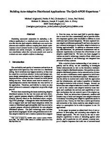
Figure 1 Chip fabrication sequence. (1) Sensors (T,P & L) are ion implanted. (2) TiSi2 wiring is formed. (3) Si3N4 coating is deposited and a membrane is etched out. (4) Two metallizations form electrodes (C) and contact areas (A). (5) A Pyrex wafer is anodic bonded to the backside.
An outline of the fabrication process is shown on Figure 1. The detailed process proceeds as follows: 1a) A 100 nm thick wet thermal oxide is grown (T=1150°C) on a 350 μm thick double polished (100) Si n-type (10 Ω-cm) substrate. Alignment marks are made by opening holes in the oxide followed by another thermal oxidation resulting in a 200 nm oxide. 1b) Ion implantation with a 2.2 μm thick AZ5214e resist as masking material is used to form the piezoresistors (B-11, 5×1014 cm-2, 50 keV), the thermistor (B-11, 4×1012 cm-2, 150 keV), the substrate conductor (B-11, 1015 cm-2, 150keV) and the substrate contact (P-31, 6×1015 cm-2, 150keV). 2a) The implanted resistors are contacted via a TiSi2 wiring system. This is made by depositing 240 nm polysilicon at 620°C followed by deposition of 106 nm Ti and a two step RTP annealing process at 600°C for 40 min and 850°C for 60 s to form the stable C54 phase of TiSi2. 3a) Both sides of the wafer are coated with a 120 nm thick LPCVD silicon nitride deposited at 800°C. 3b) Holes are opened in the nitride using wet etching in H3PO4 at 160°C, holes are opened in the underlying oxide in HF and a timed KOH etch is performed to make the membrane of the pressure sensor. The membrane is 30 μm thick defined by etch time. 3c) The nitride on the backside is then removed (in H3PO4). The nitride on the front side works as a protective coating for the sensors and is thus protected by a PECVD oxide during the etch. 4a) Contact holes are made through the nitride by reactive ion etching in a SF6/O2 plasma (32:8 sccm, 80 mTorr). 4b) A lift off process is used to define the 100/10 nm Pt/Ti layer used for the conductivity electrodes 4c) and another lift off process defines the 200/10 nm Au/Ti layer used for the bonding pads. 5a) Finally, a 500 μm pyrex wafer is anodically bonded to the backside of the wafer (at 375°C) in a low pressure forming the reference cavity for the pressure sensor.
Thermistor Temperature Sensor
Burried TiSi2 conductors
Piezoresistive Pressure Sensor Si3N4 protective coating
pn-junction Light Sensor 4 Electrode Conductivity Sensor
Pyrex Wafer
Figure 2 Picture of the fabricated chip showing the position of the different sensors. The shown end of the chip is fully exposed to the surrounding sea-water.
The fabricated sensor chip is shown on Figure 2 and the performance of the sensor is described in Refs. [4,5]. The performance of the salinity sensor is shown in Figure 3 as an example. The accuracy of the sensor is not as high as in macro size CTD profilers (0.1 psu compared to 0.005 psu) but it is sufficiently accurate for tracking purposes. The system volume is however much smaller (~5000 ×).
10
Cell impedance [Ω]
the nitride only metallization systems compatible with the deposition temperature of the nitride can be used. In the design of the sensor fabrication process a silicide (TiSi2) is chosen for conductors as it is compatible with the thermal budget and has a low resistivity. The resistive sensors have a resistance of approximately 30 kΩ to yield low power consumption while keeping a high signal to noise ratio.
4
2 psu
10
3
32 psu
10
2
10
2
3
10
4
10
5
10
Frequency [Hz] Figure 3 Conductivity cell trans-impedance as a function of frequency for 5 different salinities (2, 4, 8, 16 & 32 PSU). At medium frequencies there is a salinity sensitive window. The trans-impedance at 3.4 kHz (slashed line) is proportional to the water resistivity through the cell constant K=5.7 cm-1
THE ELECTRONIC PATCH The DST for fisheries research is an example of a specialized niche product made in low numbers and sold at a relative high cost. Therefore, this kind of system relies on conventional electronics as an ASIC (Application Specific Integrated Circuit) solution is too expensive. An example of a complex distributed sensor system designed for high volume production is the Electronic Patch sketched on Figure 4. The Electronic Patch is a new concept for
a) c)
body. Therefore, protective coatings must be defined and the packaging solution must allow for an interconnect system where all components can be integrated directly in the molded adhesive.
b)
d) e)
Figure 4 Sketch of the “The Electronic Patch”. This patch consists of a) skin friendly hydrocolloid adhesive, b) antenna, c) sensor interface and radio chip, d) battery and e) sensors for noninvasive measurement shown here for the case of a pulse oximetry measurement where SMD mounted LED’s and a photodiode are used for a reflection measurement.
non-invasive monitoring of several body functions in humans. Sensors, sensor interface electronics and a microprocessor combined in an ASIC solution, a SWM1601 radio chip [6], antenna and a battery will be integrated in a sticking patch for wireless monitoring of patients and persons at risks such as firefighters and members of SWAT teams. The Electronic Patch will include sensors for oxygen saturation, electrocardiography, pulse, and temperature measurements. As a patch is typically worn for only a few days, a battery powered solution is feasible. The patch itself is made of a hydrocolloid adhesive made specifically for on the skin applications [7]. The adhesive can be shaped by molding to integrate the electronic and micro fabricated parts of the Electronic Patch. The adhesive can absorb moisture, transmit excess moisture and will stabilize and cushion the skin. The major challenges faced by this system are the harsh environment on the skin and the combination of all components and the patch itself in a packaging solution. The humidity will be high, and sensors will have to be exposed directly to the
The Electronic Patch uses a sensor system ASIC platform. A block diagram of the ASIC is shown on Figure 5 and a picture of the ASIC chip layout is shown on Figure 6. The digital part includes the following blocks: • A LEON2 32bit RISC core CPU for control, data management and baseband communication. • Internal ROM, RAM and cache. • Analog interface controller, e.g. for control of amplification, sampling, etc. • Interface for external memory. • SPI master interface, USB interface and general purpose I/O interface. • Power management for support of various power saving modes. The analog part contains: • Instrumentation amplifiers (slow and fast) and linear amplifier. • 8 bit DAC and ADC. • Analog multiplexer. • Programmable current source and sink. Thus, both analog and digital functions are included in one chip. The SWM1601 low power radio transceiver made for Body Area Sensor Networking. The system is designed as an asymmetric master-slave system, where the master radio can synchronize one or more slave nodes. The master node will serve as the communication port between the sensors on the body and the hospital, health care service provider or team leader. The slave radio does not need a crystal oscillator as reference frequency and it regenerates the
32b Risc Core with interfaces and Analog Control Unit
Figure 5 Block diagram of the sensor interface ASIC. A LEON32 processor is combined with an analog interface, power management, internal ROM/RAM and communication interfaces.
Figure 6 Layout of the ASIC for the Electronic Patch. The processor core, the analog interface (solid box) and RAM/ROM modules (broken line) are seen.
carrier from the transmitted signal of the master radio. In the Electronic Patch the SWM1601 is using inductive near field coupling to transmit signals between the master (located on or near the body) and the slave radios (distributed on the body in the patches). The typical range of communication between the master and the slave node is 1 m to 2 m. Both the slave and master radios are two identical circuits but with different functions. The slave node can be powered by a single standard 1.2 V cell battery and being a low cost device the slave is disposed once the patch is Red raw Red avg.
0.280
Photocurrent (μA)
0.278 0.276 0.274 0.272 0.270
50
51
52
53
54
55
Time (s)
Figure 7 Pulse measured by spectrophotometry. The current from the detector photodiode is plotted as a function of time. Since the current signal is low it has 6 been amplified by a factor 10 in a transconductance amplifier. The data represented on the graph is the signal measured on the amplifier but divided with amplification factor. The pulse is easily determined to 49 beats/min.
removed. One of the sensors to be integrated in the Electronic Patch is a miniaturized pulse oximeter. Pulse oximetry is a well known technique widely used in hospitals for monitoring of the pulse and the oxygen level in the blood [8]. The optical properties of tissue are rather complex. Tissue is a turbid media where incident photons undergo multiple scattering events and absorption. In reflective pulse oximetry light that has undergone diffuse reflectance is detected. Tissue offers a limited range of wavelengths, 600nm to 1300nm that are suitable for biomedical applications. The transport of oxygen from the lungs to the rest of the body is done by hemoglobin. The oxygen saturation SaO2 is the ratio between oxygenated (HbO2) and oxygenated plus deoxygenated (Hb) hemoglobin. It can be shown that SaO2 can be calculated from the ratios between the systole and diastole scattered signals at both 940 nm (Infrared) and 660 nm (Red), respectively [8]. In the pulse oximetry setup for the Electronic Patch two light emitting diodes (wavelengths of 940 nm
and 660 nm) are used as light sources and the reflected photon intensity is detected using a silicon pn-junction photodiode. As an example of determination of the pulse in a human using spectrophotometry, Figure 7 shows the measured current from a photodiode as function of time. The heart beats are clearly visible and the pulse can be calculated from the period of the signal.
CONCLUSION Micro and Nano fabrication is an important part of future distributed sensor systems. These systems will most likely be based on silicon fabricated sensors and electronics. Major challenges ahead include: • Integration of sensors and electronics to yield ultra low power systems (using less that 100 μW) of minimal size. • System packaging will be very critical and the systems will face many different environments making universal packaging schemes unlikely. • For smaller system size and price, sensors will have to be exposed directly to harsh environments and protective coatings must be developed. • Development of reliable energy harvesting techniques is important for very low power sensor systems. • For use in bio/chemical applications on humans or animals biocompatibility is an important issue. This must be taken into account in the system packaging. When these challenges are fully met functional distributed sensor systems will become important members of the sensor technology of tomorrow.
ACKNOWLEDGEMENTS The authors gratefully acknowledge the support by the Danish Fisheries Research, Danish National Advanced Technology Foundation and the Danish Ministry of Science, Technology and Innovation.
REFERENCES 1. 2. 3. 4. 5.
6. 7. 8.
http://www.cefastechnology.co.uk J.D. Metcalfe and G.P. Arnold, Nature, (1997) 387:665-6 Neuenfeldt , H. Hinrichsen and A. Nielsen, ICES CM (2004) / L:06 A. Hyldgård, O. Hansen and E. V. Thomsen, IEEE MEMS 2005 proceedings, p. 303 A. Hyldgård, Í. Olfafsdóttir, M. Olesen, T. Hedegaard, O. Hansen & E.V. Thomsen; IEEE Sensors 2005 Proceedings, (2005), pp 1124-1127 Silicide http://www.silicide.dk/ Coloplast, http://www.coloplast.com J. G. Webster, Design of Pulse Oximeters, Institute of Physics Publishing, 1997