224
IPTEK, Journal of Proceeding Series, Vol. 1, 2014 (eISSN: 2354-6026)
Distribution Network Efficiency Improvement Based on Fuzzy Multi-objective Method Ramadoni Syahputra1, Imam Robandi1, and Mochamad Ashari1 AbstractThis paper presents a reconfiguration methodology based on a fuzzy multi-objective approach for achieving the minimum active power loss and the maximum voltage magnitude of radial distribution networks with distributed generations in order to improve the distribution system efficiency. Multi-objective function are considered for load balancing among the feeders, minimization of the real power loss, and deviation of bus voltage, while subject to a radial network structure in which all loads must be energized. These objective functions are modeled with fuzzy sets to evaluate the imprecise nature of each objective. Originality of the research is that the fuzzy-based multi-objective optimization in reconfiguration of distribution network including the distributed generation. The implementation of the fuzzy multi-objective for distribution reconfiguration on a 77 bus distribution network with distributed generation is described. The simulation results show that a 1.80% of electric power distribution network efficiency improvement is achieved by the method.. Keywords Distribution network, DG, fuzzy multiobjective, reconfiguration, efficiency.
I. INTRODUCTION1
D
istributed Generation (DG) is typically defined as small generators, less than 10-MW, commonly powered by renewable energy sources that are connected to transmission or distribution systems [1]. The great demands of renewable energy resources with respect to energy reserve and environmental issues make the new technologies such as fuel cells, photovoltaics, wind farms, and other resources more and more popular. The government of Indonesia has targeted that DGs from renewable energy resources will be on-grid for up to 25% by the year 2025 [2]. Installation of DGs in electrical power distribution network creates a variety of well-documented impacts in with voltage rise, which is the dominant effect distribution system in rural networks [3-4]. Traditional options to mitigate adverse impacts remain costly for developers and Distribution Network Operators. With the increasing levels of generation to be accommodated, planning and design of distribution networks will need to change to harness approaches that use information and communication technology to actively manage the network (e.g., network reconfiguration [5]). Electrical power distribution systems have switches to configure the networks. There are two types of switch in the system, tie switch and sectionalizing switch, whose states determine the configuration of distribution network. Reconfiguration of the network is built through switching operation on switches of distribution network bus. In modern power distribution systems, the multipleobjective feeder reconfiguration problem has assumed significant importance. The multiple objectives are considered for load balancing among the feeders and minimize the active power loss, while subject to a radial network structure in which all loads must be energized. Distribution networks are configured radially. Their configurations may be varied with manual or automatic switching operations so that the loads are supplied at the cost of possible minimum resistive line losses, increase 1
Ramadoni Syahputra, Imam Robandi, and Mochamad Ashari are with Departement of Electrical Engineering, Faculty of Industrial Engineering, Institut Teknologi Sepuluh November, Surabaya, 60111, Indonesia. E-mail:
[email protected];
[email protected],
[email protected].
system security and enhance power quality. Reconfiguration also reduces and relieves the overloading of the network feeders. The change in network configuration is performed by opening or closing of tie-switches and sectionalizing-switches of the network. These switching are performed in order to maintain the radially of the network with regard to all the loads are energized. Many researches in literature have been focused for loss reduction with reconfiguration of distribution networks [6]. Distribution network reconfiguration with aim for loss reduction was first proposed by Merlin and Back [7]. They have used a branch and bound type optimization technique to determine the minimum loss configuration. In this method, all network switches are first closed to form a meshed network. The switches are then opened successively to restore radial configuration. After that, many algorithms that aim to reduce the power loss of distribution system. Zhou et al. [8] have proposed two algorithms for distribution reconfiguration in order to service restoration and load balancing. Their methodologies were using combination of heuristic rules and fuzzy logics in optimization purposes for efficiency and robust performance. An optimization method to determine the network configuration with minimum energy losses for a given period has proposed by Taleski and Rajicic [9]. Borozan and Rajakovic [10] have considered the application aspects of optimal distribution network reconfiguration. Lin and Chin [11] have presented an algorithm of network reconfiguration using voltage index, ohmic index, and decision index to determine the switching operation. Jeon et al. [12] and Augugliaro et al. [13] have proposed artificial-intelligence-based applications in a minimum loss reconfiguration. Nara et al. [14] have proposed network reconfiguration techniques for minimum loss using a genetic algorithm (GA). Das [15] have proposed an algorithm based on the fuzzy multi-objective approach for optimizing distribution network configuration. The four objectives load balancing among the feeders, real power loss, deviation of bus voltage, and branch current constraint violation are modeled and results obtained are encouraging, but criteria for selecting a membership function for each objective are not provided. The use of
IPTEK, Journal of Proceeding Series, Vol. 1, 2014 (eISSN: 2354-6026) harmony search algorithm (HSA) for optimal network reconfiguration of large-scale distribution system has presented by Rao et al. [16]. The algorithm is a technique which is conceptualized using the musical process of searching for harmony in perfect state. It uses a stochastic random search instead of a gradient search which eliminates the need for derivative information. In this research, the formulations of the distribution network reconfiguration problem as a multiple objectives problem subject to operational and electric constraints are performed. The problem formulations presented herein consider four different objectives related to: minimization of the system’s active power loss; minimization of the deviation of bus voltage; minimization of the branch current constraint violation; and load balancing among various feeders. Radially of the network must remain after reconfiguration in which all loads must be simultaneously energized. These four objectives are modeled with fuzzy sets. Heuristic rules are also incorporated in the algorithm for minimizing the number of tie-switch operations. The objective of this research is to show that the fuzzy multi-objective can be used successfully in the reconfiguration of electrical distribution networks with distributed generation to minimize the active power losses of the system and to balance the loading of the feeders. II. FUZZY MULTI-OBJECTIVE METHOD Fuzzy multi-objective method in this paper has developed by Das [15]. In domain of fuzzy system, each objective is associated with a membership function. The membership function refers the degree of satisfaction of the objective. In the crisp domain, either the objective is satisfied or it is violated, implying membership values of unity and zero, respectively. On the contrary, fuzzy sets entertain varying degrees of membership function values from zero to unity. Thus, fuzzy set theory is an extension of standard set theory. When there are multiple objectives to be satisfied simultaneously, a compromise has to be made to get the best solution. The four objectives described in this research are first fuzzified. After that, the results of the fuzzification are integrated into a fuzzy satisfaction objective function J through appropriate weighting factors. In the proposed method for network reconfiguration, the terms mLi, mVi, mAi and mBi indicate the membership function for real power loss reduction, maximum bus voltage deviation, maximum branch current loading index and load balancing of the feeders, respectively. The higher membership value implies a greater satisfaction with the solution. The membership functions in fuzzy system that consists of a lower and upper bound value are described below. A. Active Power Loss Reduction Membership Function The aim of the constructing of this membership function is to reduce the active power loss of the system. Let us define
xi
Ploss( i ) Ploss( 0 )
,
for i 1,2,3,..., N k
(1)
where, Nk is the total number of branches in the loop
225
including tie-branch, when i-th tie-switch is closed, Ploss(i) is the total real power loss of the radial configuration of the system when i-th branch in the loop is opened, and Ploss(0) is the total real power loss before network reconfiguration. From equation (1) can be expressed that if x i is high, power loss reduction is low and, hence, a lower membership value is assigned and if xi is low, the power loss reduction is high and a higher membership value is assigned. The membership function for real power loss reduction is given in Fig. 1. From Fig. 1, µLi can be written as
Li
( x max x i ) , ( x max x min )
for x min x i x max
(2)
Li 1, for xi xmin Li 0, for xi xmax It has been assumed that xmin = 0.5 and xmax = 1. This means if the loss is 50% or less of the P loss(0), the unity membership value is assigned and if the loss is 100% or more of Ploss(0), the zero membership value is assigned. B. Maximum Bus Voltage Deviation Membership Function The aim of the constructing of this membership function is that the deviation of bus voltage should be less. Let us define
yi max | Vi , j Vs |,
for i 1,2,3,..., N k j = 1, 2, 3, …, NB.
(3)
where, Nk is total number of branches in the loop including the tie branch, when the i-th tie switch is closed; NB is total number of bus of the system; Vs is voltage of the substation (in per unit); and Vi,j is voltage of bus corresponding to the opening of the i-th branch in the loop (in per unit). In fuzzy environment of the research, if the maximum voltage deviation is less, then a higher membership value is assigned and if deviation is more, then a lower membership value is assigned. Fig. 2 shows the membership function for maximum bus voltage deviation. From Fig. 2, we can write
Vi
( y max y i ) , ( y max y min )
for y min y i y max
(4)
Vi 1, for yi ymin Vi 0, for yi ymax In the present work, ymin = 0.05 and ymax = 0.10 have been considered. ymin = 0.05 means if the substation voltage is 1.0 p.u., then the minimum system voltage will be 0.95 p.u. and if the minimum system voltage is greater than or equal to 0.95 p.u., the unity membership value is assigned. Similarly, if ymax = 0.10, the minimum system voltage will be 0.90 p.u. and if the minimum system voltage is less than or equal to 0.90 p.u., the zero membership value is assigned. C. Maximum Branch Current Loading Index Membership Function The basic purpose for this membership function is to minimize the branch current constraint violation. Let us
226
IPTEK, Journal of Proceeding Series, Vol. 1, 2014 (eISSN: 2354-6026)
define | I (i, m) | Branch current loading index , I c ( m)
(5)
for i 1,2,3,..., N k , and m 1,2,3,..., NB 1.
where, Nk is total number of branches in the loop including the tie branch when the i-th tie switch is closed; |I(i,m)| is magnitude of current of branch-m when the ith branch in the loop is opened; I c(m) is line capacity of branch-m; NB is total number of the bus of the system. Let us define
I (i, m) zi max , I c ( m)
for i 1,2,3,..., N k , and
(6)
m 1,2,3,..., NB 1. When the maximum value of branch current loading index exceeds unity, a lower membership value is assigned and as long as it is less than or equal to unity, the maximum membership value is assigned (i.e., unity). The membership function for the maximum branch current loading index is shown in Fig. 3. From Fig. 3, we can write
ui, a higher membership grade is assigned and for higher ui, a lower membership grade is assigned. Fig. 4 shows the membership function for ui. From Fig. 4, we can write
Bi
(u max u i ) , (u max u min )
for u min u i u max (10)
Bi 1, for ui umin Bi 0, for ui umax In this case, umin = 0.10 and umax = 0.50 have been considered. umin = 0.10 indicates that the maximum deviation of feeder currents will be 10% with respect to the maximum value of feeder current and if this deviation is less than or equal to 10%, the unity membership value is assigned and umax = 0.50 indicates that if this deviation is greater than 50%, a zero membership value is assigned. F. Algorithm of Fuzzy Multi-objective An algorithm for the reconfiguration is shown in Fig.5. III. SIMULATION RESULTS
Ai
( z max z i ) , ( z max z min )
Ai 1, Ai 0,
for z min z i z max (7)
for zi z min for zi z max
In this case, zmin = 1.0 and zmax = 1.15 have been considered. zmin = 1.0 indicates that as long as the branch currents of the system are less than or equal to their respective line capacity, unity membership value is assigned and zmax = 1.15 indicates that 15% overloading is allowed for each branch and if in any branch, the current is greater than or equal to 1.15 times the line capacity, a zero membership value is assigned. D. Feeder Load Balancing Membership Function Load balancing is one of the major objectives of feeder reconfiguration. An effort to increase the loading margin of heavily loaded feeders of distribution system is to transfer part of their loads to lightly loaded feeders. Feeder load balancing index may be given as FLBi , j
( IFFi , max IFi , j ) IFFi , max
,
for i 1,2,3,..., N k , and (8)
j 1,2,3,..., NF . where, Nk is total number of branches including the tie branch in the loop when the th tie switch is closed; NF is total number of feeders; IFi,j is current of feeder corresponding to the opening of the th branch in the loop; IFFi,max is is the maximum of all the feeder currents corresponding to the opening of the i-th branch in the loop = max(IFi,j), for j = 1, 2, 3, …, NF.
E. Let us define
ui max( FLBi , j ),
for i 1,2,3,..., N k , and j 1,2,3,..., NF .
(9)
Equation (9) indicates that a better load balancing can be achieved if the value of ui is low. Therefore, for lower
In this study, we have tested the 20-kV radial distribution system having one substation, two feeders, and 77 bus (including sectionalizing branches and tie branches) as shown in Fig.6. This system has 114 sectionalizing branches and 10 tie branches. Tie switches of this system are open in normal conditions. Fig.6 shows the initial configuration of distribution network without distributed generations. The optimization of reconfiguration of distribution network with distributed generation using fuzzy multi-objective was implemented in Matlab software, and the simulations were performed on an Intel Pentium ® core(TM) 2 duo CPU, 1.80 GHz, 4 GB RAM. Before reconfiguration the network, the total active power loss of this system is 229.64 kW. The minimum voltage magnitude that occurs in bus of 17 is 0.891 p.u. In this work, we have installed seven distributed generations (DGs) in bus of 5, 7, 14, 22, 28, 34, 36, 41, 46, 54, 59, 68, 70 and 74, respectively, as shown in TABLE I. From the result of our case study, it can be seen from the 77-bus test system that DG has the effects of loss reduction improvement over feeders in this particular case. The total active power loss of this system with DGs is 179.87 kW, or, in other words that the efficiency of distribution network is 94.63%, as shown in TABLE II. The minimum voltage magnitude that occurs in bus of 17 is 0.907 p.u. After reconfiguration, the total active power loss is 165.07 kW, or the other words, the efficiency of distribution network is 95.05%, as shown in TABLE II. The minimum voltage magnitude is 0.918 p.u. that occurs in bus of 45. Fig.7. shows distribution of power loss for each bus of distribution network before reconfiguration,
IPTEK, Journal of Proceeding Series, Vol. 1, 2014 (eISSN: 2354-6026) while Fig.8 shows distribution of power loss for each bus of distribution network after reconfiguration. It is observed that the losses in almost every branch is reduced, except at 4, 6, 16, 17, 18, 19, 20, and 53, where the losses are increased because of shifting of loads onto these feeders. From the result of our case study, it can be seen from the 77 bus radial distribution system test system that DG has the effects of loss reduction improvement over feeders in this particular case, and the topological structures of optimum network without DG are different from those with DG. Based on the 77 bus radial distribution system with DG, the presented method in this paper has significant loss reduction in order to improve the efficiency of distribution system with distributed generation (DG).
[3].
[4].
[5].
[6].
[7].
[8].
[9].
IV. CONCLUSION
An efficient methodology for optimal reconfiguration of distribution networks including distributed generation has been presented in this paper. The effectiveness of the method has been demonstrated by a 77-bus distribution network test system. The main advantage of the presented method is the capabilities of reducing the active power losses and increasing the voltage magnitude of bus of distribution network. The simulation results show that a 1.80% of electric power distribution network efficiency improvement is achieved by the method.
[10].
ACKNOWLEDGEMENT
[14].
The authors gratefully acknowledge the contributions of the Directorate General of Higher Education (DIKTI), Ministry of Education and Culture, Republic of Indonesia, for funding this research REFERENCES [1].
[2].
A.M. Borbely and J.F. Kreider, “Distributed Generation: The Power Paradigm for the New Millennium”, CRC Press, Washington D.C., 2001. D. Kusdiana, “Kondisi Riil Kebutuhan Energi di Indonesia dan Sumber-Sumber Energi Alternatif Terbarukan”, Presented at the Seminar of Renewable Energy, Direktorat Jenderal Listrik dan
[11].
[12].
[13].
[15].
[16].
[17].
227
Pemanfaatan Energi Departemen Energi dan Sumber Daya Mineral, Bogor, 3 Dec. 2008. S. Civanlar, J. J. Grainger, H. Yin, and S. S. H. Lee, “Distribution Feeder Reconfiguration for Loss Reduction,” IEEE Trans. Power Del., vol. 3, no. 3, pp. 1217–1223, Jul. 1988. M. E. Baran and F. F.Wu, “Network Reconfiguration in Distribution Systems for Loss Reduction and Load Balancing,” IEEE Transaction on Power System, vol. 4, no. 3, pp. 1401– 1407, Aug. 1989. C. S. Chen and M. Y. Cho, “Energy Loss Reduction by Critical Switches,” IEEE Trans. Power Delivery, vol. 8, no. 3, pp. 1246– 1253, Jul. 1993. V. Borozan, D. Rajicic, and R. Ackovski, “Improved Method for Loss Minimization in Distribution Networks,” IEEE Transaction on Power System, vol. 10, no. 3, pp. 1420–1425, Aug. 1995. A. Merlin and H. Back, “Search for a minimal-loss operating spanning tree configuration in an urban power distribution system,” in Proc. 5th Power System Computation Conf., Cambridge, U.K., 1975, pp. 1–18. Q. Zhou, D. Shirmohammadi, and W. H. E. Liu, “Distribution Feeder Reconfiguration for Service Restoration and Load Balancing,” IEEE Trans. Power Syst., vol. 12, no. 2, pp. 724– 729, May 1997. R. Taleski and D. Rajicic, “Distribution Network Reconfiguration for Energy Loss Reduction,” IEEE Transaction on Power System, vol. 12, no. 1, pp. 398–406, Feb. 1997. V. Borozan and N. Rajakovic, “Application Assessments of Distribution Network Minimum Loss Reconfiguration,” IEEE Transaction on Power Delivery, vol. 12, no. 4, pp. 1786–1792, Oct. 1997. W. M. Lin and H. C. Chin, “A New Approach for Distribution Feeder Reconfiguration for Loss Reduction and Service Restoration,” IEEE Transaction on Power Delivery, vol. 13, no. 3, pp. 870–875, Jul. 1998. Y. J. Jeon, J. C. Kim, J. O. Kim, J. R. Shin, and K. Y. Lee, “An Efficient Simulated Annealing Algorithm for Network Reconfiguration in Large-Scale Distribution Systems,” IEEE Transaction on Power Delivery, vol. 17, no. 4, pp. 1070–1078, Oct. 2002. A. Augugliaro, L. Dusonchet, M. Ippolito, and E. R. Sanseverino, “Minimum Losses Reconfiguration of MV Distribution Networks Through Local Control of Tie-Switches,” IEEE Transaction on Power Delivery, vol. 18, no. 3, pp. 762– 771, Jul. 2003. K. Nara, A. Shiose, M. Kitagawa, and T. Ishihara, “Implementation Of Genetic Algorithm for Distribution System Loss Minimum Reconfiguration,” IEEE Transaction on Power Delivery, vol. 7, no. 3, pp. 1044–1051, Aug. 1992. D. Das, “A Fuzzy Multi-Objective Approach for Network Reconfiguration of Distribution Systems,” IEEE Transaction on Power Delivery, vol. 21, no. 1, pp. 202–209, Jan. 2006. R.S. Rao, S.V.L. Narasimham, M.R. Raju, and A.S. Rao, “Optimal Network Reconfiguration of Large-Scale Distribution System Using Harmony Search Algorithm”, IEEE Transactions on Power Systems, Vol. 26, No. 3, pp. 1080-1088, Aug. 2011. V. Farahani, B. Vahidi, and H.A. Abyaneh, “Reconfiguration and Capacitor Placement Simultaneously for Energy Loss Reduction Based on an Improved Reconfiguration Method”, IEEE Trans on Power System, Vol. 26, No. 2, 2011.
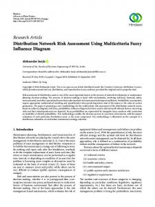
Figure 1. Membership function for power-loss reduction
Figure 3. Membership function for current loading index
Figure 2. Membership function for voltage deviation
Figure 4. Membership function for the load balancing index
228
IPTEK, Journal of Proceeding Series, Vol. 1, 2014 (eISSN: 2354-6026)
Start
Read system data
Run the load-flow program
Compute ∆𝑉𝑡𝑖𝑒 (𝑖) for i = 1,2,…, n-tie
Identify ∆𝑉𝑡𝑖𝑒,𝑚𝑎𝑥 = ∆𝑉𝑡𝑖𝑒 (𝑘)
𝑉𝑡𝑖𝑒,𝑚𝑎𝑥 > 𝜀 ?
No
Output result
Yes Select the tie switch “k” and identify the Nk
For i = 1 to Nk, compute µLi, µVi, µAi, and µBi using (2), (4), (7), and (10), respectively, and evaluate: Dk,i = min{µLi,µVi,µAi,µBi}; Obtain OSk = max{Dk,i}, for i = 1, 2, …, Nk
Output result
Stop Figure 5. Algorithm for network reconfiguration
Figure 6. A 77-bus distribution system [17]
IPTEK, Journal of Proceeding Series, Vol. 1, 2014 (eISSN: 2354-6026) Distribution of Power Losses After Reconfiguration
35
35
30
30 Power losses (kW)
Power losses (kW)
Distribution of Power Losses Before Reconfiguration
229
25 20 15 10
25 20 15 10 5
5
0
0 1
11
21
31 41 51 Number of bus
61
71
Figure 7. Distribution of power loss before reconfiguration TABLE I INSTALLATION BUS AND CAPACITY OF DG Capacity (kW)
Power Factor
5
150
0.8
7
100
0.9
14
100
0.9
22
100
1
28
150
0.9
34
50
0.8
36
100
0.9
41
150
0.8
46
100
0.9
54
200
0.9
59
100
1
68
200
0.9
70
50
0.8
74
100
0.9
Bus
1
11
21
31 41 51 61 71 Number of bus Figure 8. Distribution of power loss after reconfiguration TABLE II THE RESULTS OF SIMULATION OF 77 BUS DISTRIBUTION NETWORK Parameters of Analysis Active Power Loss (kW)
Efficiency of Distri-bution Network (%)
Minimum Voltage (p.u.)
Distribution network without DG before reconfigura-tion
229.64
93.25
0.891 (V17)
Distribution network with DG before reconfigura-tion
179.87
94.63
0.902 (V17)
Distribution network with DG after reconfigura-tion
165.07
95.05
0.918 (V45)
Test Case