technologies Review
Overhanging Features and the SLM/DMLS Residual Stresses Problem: Review and Future Research Need Albert E. Patterson 1,2, *, Sherri L. Messimer 1 and Phillip A. Farrington 1 1
2
*
Department of Industrial and Systems Engineering and Engineering Management, University of Alabama in Huntsville, Technology Hall N143, 301 Sparkman Drive, Huntsville, AL 35899, USA;
[email protected] (S.L.M.);
[email protected] (P.A.F.) Department of Industrial and Enterprise Systems Engineering, University of Illinois at Urbana-Champaign, Transportation Building 117, 104 South Mathews Avenue, Urbana, IL 61801, USA Correspondence:
[email protected] or
[email protected]; Tel.: +1-256-824-5290
Academic Editors: Salvatore Brischetto, Paolo Maggiore and Carlo Giovanni Ferro Received: 24 March 2017; Accepted: 10 April 2017; Published: 12 April 2017
Abstract: A useful and increasingly common additive manufacturing (AM) process is the selective laser melting (SLM) or direct metal laser sintering (DMLS) process. SLM/DMLS can produce full-density metal parts from difficult materials, but it tends to suffer from severe residual stresses introduced during processing. This limits the usefulness and applicability of the process, particularly in the fabrication of parts with delicate overhanging and protruding features. The purpose of this study was to examine the current insight and progress made toward understanding and eliminating the problem in overhanging and protruding structures. To accomplish this, a survey of the literature was undertaken, focusing on process modeling (general, heat transfer, stress and distortion and material models), direct process control (input and environmental control, hardware-in-the-loop monitoring, parameter optimization and post-processing), experiment development (methods for evaluation, optical and mechanical process monitoring, imaging and design-of-experiments), support structure optimization and overhang feature design; approximately 143 published works were examined. The major findings of this study were that a small minority of the literature on SLM/DMLS deals explicitly with the overhanging stress problem, but some fundamental work has been done on the problem. Implications, needs and potential future research directions are discussed in-depth in light of the present review. Keywords: additive manufacturing; 3D printing; metal additive manufacturing; selective laser melting (SLM); direct metal laser sintering (DMLS); metal powder processing
1. Introduction Additive manufacturing (AM) technologies, commonly known as 3D printing tools, are a family of manufacturing processes that produce solid geometries by “joining [raw] materials to make objects from 3D model data, usually layer upon layer, as opposed to subtractive manufacturing methods” [1]. While most commonly-used and established AM processes use plastics and photopolymers as the initial raw material, a number of AM processes that can process metals (usually in the form of fine powder) are emerging and being rapidly developed and perfected. The availability of such fabrication tools offers great promise to many sectors of manufacturing, especially the aerospace, medical and automotive industries, in their ever-growing quest for lighter, stronger, tougher, more complex and more cost-efficient metal parts. One of the most promising and flexible of these metal-printing processes is known as selective laser melting (SLM) or direct metal laser sintering (DMLS). The process is known by both names, depending on the geographical area of the user; in the early days of development, “SLM” was most Technologies 2017, 5, 15; doi:10.3390/technologies5020015
www.mdpi.com/journal/technologies
Technologies 2017, 5, 15
2 of 21
commonly used in Europe and “DMLS” in the USA, but both names have been used synonymously as the technology has matured over the past decade or so. Compared to other metal-melting AM process, such as electron beam melting (EBM), SLM/DMLS is very cost effective, works well with a wide variety of elemental metals and alloys, produces an excellent surface finish, provides excellent feature resolution and is more industrially safe [2–4]. Unfortunately, the SLM/DMLS process is dominated by one serious weakness, which is preventing its more wide-spread acceptance and use as a standard manufacturing process: the tendency of the process to build an unbalanced stress profile into the part between the layers during processing. This has become known as the residual stresses problem and has been the topic of research since the process was first introduced. The collection of both general and regional residual stresses into parts without a way for them to naturally dissipate (as they do in non-metal AM processes) can be a major problem because this can initiate cracks, warpage and delamination if the part is not properly designed or has delicate features, both during and after processing, and can reduce the fatigue strength of the part by a factor of 10 or more when compared to bulk-formed parts [5–8]. These problems are especially apparent and challenging in parts that have overhanging or protruding features, as the stresses tend to build up more seriously in and near these features during printing [5,9]; this can cause severe warping and damage to the features and cause the destruction of the entire part, sometimes before it is even finished printing. Temporary support structure can be used to prevent in-process failure, but using these in SLM/DMLS can come with its own set of problems. With careful part design, use of special support structures for delicate features and various rules-of-thumb developed over the years, the process can be used successfully for specific applications; however, it would be far more useful and trustworthy, more cost efficient and more widely accepted if a general theory of design were available for the parts that will be created using SLM/DMLS. 2. The SLM/DMLS Residual Stresses Problem According to the U.S. patent for SLM/DMLS, the process is a variation of the powder bed fusion process in which a thin layer of “metallic powder free of binding and fluxing agents” is selectively “heated by [a] laser beam to melting temperature” in order to fuse it into a solid slice of material in the correct shape of the part. The laser beam energy “is chosen in such a way that the layer of metallic powder is fully molten throughout its layer thickness at the point of impact of [the] laser beam” and the laser beam is “guided across a specified area of the powder material layer ... in such a way that each run partially overlaps the preceding run” in order to form proper metallic bonds between scans (and between the current layer and previous layers) and therefore produce a homogeneous solid. The entire operation is run in a “protective gas environment” during the described procedures to prevent unwanted reactions and oxidations. Because the powdered material is “free of binding and fluxing agents” and because it is “heated to its melting temperature throughout the layer thickness”, the resulting solid has mechanical properties similar to bulk-formed materials [10]. As each layer is selectively melted in this way, the build table in the printer drops down the distance of one layer thickness (20–100 µm), and a wiper deposits a fresh layer of new unmelted powder, starting the whole operation over again. This cycle continues until the part is complete [5–7,11]. Traditionally, only metallic materials could be used with SLM, but some work has been done to extend the process to ceramics and metal/ceramic/polymer composites [12–14]. Figure 1 demonstrates the basic anatomy and process chain for SLM/DMLS.
Technologies2017, 2017,5, 5,15 15 Technologies Technologies 2017, 5, 15
22 3 of 21 3 of 22
Figure process mechanics. mechanics. Figure 1. 1. SLM/DMLS SLM/DMLS process Figure 1. SLM/DMLS process mechanics.
By definition, definition, “residual “residual stresses” stresses” are are the the stresses stresses within within aa plasticallyplastically- or or elastically-deformed elastically-deformed By By definition, “residual stresses” are the stresses within a plasticallyor elastically-deformed material that that remain remain within within the the structure structure after after the the load load that that deformed deformed it it is is removed removed [15]. In In the the SLM SLM material [15]. material that remain within the structure after the load that deformed it is removed [15].across In the each SLM process, the major source of the residual stresses is the heat cycling as the laser scans process, the major source of the residual stresses is the heat cycling as the laser scans across each layer, process, the major source of the residual stresses is the heat cycling as the laser scans across each layer, where previously solidified layers are re-melted and cooled at inconsistent where previously solidified layers are re-melted and cooled several several times attimes inconsistent levels oflevels heat. layer, where previously are re-melted and cooled several times at inconsistent levels of heat. When looking atsolidified the stresslayers gradients in a particular single layer of the part during heating, When looking at the stress gradients in a particular single layer of the part during heating, the two of heat. When looking at the stress gradients in a particular single layer of the part during heating, the two most important regions are the layerto(exposed thethe laser) and the interface most important regions are the top of the the top layerof(exposed the laser)to and interface between the the two most important regions are the (Figure top of 2). the layer (exposed to the laser) and the interface between the layer and the previous layer layer and the previous layer (Figure 2). between the layer and the previous layer (Figure 2).
Figure 2. Stress gradients in single layers. Figure 2. Stress gradients in single layers.
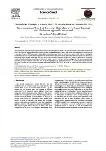
Due to to thermal thermal expansion, expansion, the top of of the the layer layer experiences experiences aa tensile tensile stress, stress, while while the the cooler cooler Due the top Due to thermal expansion, the top of the layer experiences a tensile stress, while the cooler interface has onon it. it. If only one one layerlayer werewere to be to printed, this would not be interface has compressive compressivestresses stressesacting acting If only be printed, this would interface has compressive stresses acting on it. If only one layer were to be printed, this would not be a problem, as the stresses would dissipate naturally once the material cooled. The problem manifests not be a problem, as the stresses would dissipate naturally once the material cooled. The problem a problem, as the stresses would dissipate naturally once the material cooled. The problem manifests itself when thewhen underlying layers layers restrictrestrict the thermal expansion andand contraction manifests itself the underlying the thermal expansion contractionofofthe the layers layers itself when the underlying layers restrict the thermal expansion and contraction of the layers immediately below the melt pool; this can occur several layers deep simultaneously and can happen immediately below the melt pool; this can occur several layers deep simultaneously and can happen immediately below the melt pool; this can occur several layers deep simultaneously and can happen multiple times times to to the the same same layer layer throughout throughout the the build, build, and and the the material material does does not not necessarily necessarily need need to to multiple multiple times to the same layer throughout the build, and the material does not necessarily need to be molten molten for for it it to to happen. happen. This the layers, resulting in in be This can can cause cause an an elastic elastic compressive compressive strain strain within within the layers, resulting bestress molten for it tobetween happen.the Thislayers can cause elastic compressive within the layers, in gradient [8,9].an Figure demonstratesstrain this graphically. graphically. Whereresulting the layers layers aa stress gradient between the layers [8,9]. Figure 33 demonstrates this Where the a stress gradient between the layers [8,9]. Figure 3 demonstrates this graphically. Where the layers are free free to to move move (Figure (Figure 3a), 3a), the the residual residual stress are stress between between the the layers layers is is low; low; it it is is not not zero, zero, however, however, are free to move (Figure 3a), the residual stress between the layers is low; it is not zero, however, since some thethe layers areare restricted from moving by since some friction friction will willstill stillexist existbetween betweenthe thelayers. layers.Where Where layers restricted from moving since some friction willstresses still exist between the layers.because Where the layers areallowed restricted from moving by fusion (Figure 3b), the can build up quickly they are not to move freely and by fusion (Figure 3b), the stresses can build up quickly because they are not allowed to move freely fusion (Figure 3b), the stresses can build up quickly because they are not allowed to move freely and therefore can become warped as the subsequent layers are heated. Figure 4 shows an example therefore can become warped as the subsequent layers are heated. Figure 4 shows an example
Technologies 2017, 5, 15
4 of 21
Technologies Technologies 2017, 2017, 5, 5, 15 15
44 of of 22 22
and therefore can become warped as the subsequent layers are heated. Figure 4 shows an example finite-element finite-element (FEA) (FEA) model model of of the the thermal thermal deformations deformations during during laser laser scanning; scanning; the the material material shown shown is is finite-element (FEA) model of the thermal deformations during laser scanning; the material shown six temperature, with six layers layers (50 (50 μm) μm) of of 316 316 stainless stainless steel, steel, with with aa 200-W 200-W laser laser input input and and 24 24 °C °C ambient ambient temperature, with is six layers (50 µm) of 316 stainless steel, with a 200-W laser input and 24 ◦ C ambient temperature, the the base base fixed fixed to to the the build build plate. plate. This This model model is is for for concept concept demonstration demonstration only only and and not not aa new new research research with the base fixed to the build plate. This model is for concept demonstration only and not a new tool; tool; no no new new powder powder is is added added in in this this figure, figure, this this is is simply simply the the deformation deformation of of the the material material under under research tool; no new powder is added in this figure, this is simply the deformation of the material laser load. laser load. under laser load.
Figure 3. Stress between layers. Figure Figure 3. 3. Stress Stress between between layers. layers.
Figure Figure 4. 4. Stress Stress between between layers layers (FEA (FEA deformation deformation example). example). Figure 4. Stress between layers (FEA deformation example).
Several Several published published studies studies explicitly explicitly described described the the specific specific mechanics mechanics of of the the stress stress formulation formulation as as Several published studies explicitly described the specific mechanics of the stress formulation described described above, above, most most notably notably in in the the works works of of Mercelis Mercelis and and Kruth Kruth [9] [9] and and Knowles Knowles et et al. al. [8]. [8]. Other Other as described above, most notably in the were works of Mercelis andet [9] and Knowleset al.[18], [8]. studies that this those by al. Matsumoto studies that discussed discussed this issue issue in in depth depth were those by Roberts Roberts etKruth al. [16,17], [16,17], Matsumoto etetal. al. [18], Other studies that discussed this issue in depth were those by Roberts et al. [16,17], Matsumoto et al. [18], Gu Gu et et al. al. [19], [19], Guo Guo and and Leu Leu [4] [4] and and Van Van Belle Belle et et al. al. [20]. [20]. Gu etThere al. [19], Guo and Leu [4] and Van Belle et al. [20]. stresses There are are aa number number of of ways ways to to combat combat the the residual residual stresses problem problem when when printing printing very very simple simple a number combat the residual stresses problem when simple parts; most parts created by SLM physically connected to build at the helping to parts;There mostare parts createdof byways SLMtoare are physically connected to the the build plate plate atprinting the base, base,very helping to parts; most parts created by SLM are physically connected to the build plate at the base, helping to both both support support and and tie tie down down the the layers layers until until the the part part body body is is large large enough enough to to support support the the stresses. stresses. This This is is accomplished accomplished by by fusing fusing the the first first layer layer of of powder powder directly directly to to the the build build plate plate as as if if it it were were the the material material substrate; substrate; this this is is common common knowledge knowledge in in the the world world of of metal metal powder powder manufacturing. manufacturing. Unfortunately, Unfortunately,
Technologies 2017, 5, 15
5 of 21
both support and tie down the layers until the part body is large enough to support the stresses. This is accomplished by fusing the first layer of powder directly to the build plate as if it were the material substrate; this2017, is common knowledge in the world of metal powder manufacturing. Unfortunately, Technologies 5, 15 5 of 22 there is little experimentally-based information to be found concerning the effects of the residual there little experimentally-based to be found concerningfeatures the effects of the5). residual stresses onisthe design of complex partsinformation with overhanging or protruding (Figure Most of the stresses on the design of complex parts with overhanging or protruding features (Figure 5). Most of studies typically discussed in literature searches discuss rule-of-thumb ways to physically prevent the the studies typically discussed in literature searches discuss rule-of-thumb ways to physically stresses from destroying the parts during printing and are little concerned with trying to understand prevent the stresses from destroying the parts during printing and are little concerned with trying to the mechanics of the stresses andstresses how and theyhow directly affect affect the overhanging features. understand the mechanics of the they directly the overhanging features. There There was considerable discussion of this problem in the studies by Hussein et al. [21,22], Matsumoto etal. al. [18], was considerable discussion of this problem in the studies by Hussein et al. [21,22], Matsumoto et Calingnano [23], Mohanty and Hattel [24], Zeng [25], Li et al. [26] and Gan and Wong [27], but [18], Calingnano [23], Mohanty and Hattel [24], Zeng [25], Li et al. [26] and Gan and Wong [27], but these addressed application-specific issuesissues and and did did notnot discuss the level of feature these addressed application-specific discussthe the problem problem atatthe level of feature and and design. part part design.
Figure Examplesof of overhanding overhanding and part features. Figure 5. 5.Examples andprotruding protruding part features.
Some of the opinions commonly heard from practitioners are that the overhanging features are
Someseverely of the affected opinions heard from practitioners arewelded that the most bycommonly the stresses because they are not physically to overhanging the build plate features during are mostthe severely affected by the stresses because they are not physically welded to the build plate during printing and are thinner and less resistant to thermal shock. Depending on the specific geometry, the printing and are thinner and less resistant to thermal shock. Depending on the specific geometry, stress concentrations between the features and the main parts also likely play a role in magnifying effect. However, there is the littlefeatures rigorousand treatment of this in the technical to verify if these the stressthe concentrations between the main parts also likely literature play a role in magnifying opinions are indeed forrigorous general cases. The current study to discover more in-depth effect. However, there istrue little treatment of this in the hopes technical literature to verify if these answers to these questions. opinions are indeed true for general cases. The current study hopes to discover more in-depth answers Up to now, the best solution has been to use strong support materials, in spite of some problems to these questions. using both a powder bed and supports; concerns included the required extra post-processing, extra Up to now, the best solution has been to use strong support materials, in spite of some problems material use, increased cycle time, increased risk of damage to the part, damage to the finish of the usingpart both a powder bed and supports; concerns included the required extra post-processing, extra from support removal and restrictions on the part design to accommodate the support structure; material use, increased cyclesupport time, increased ofSLM. damage tostudies the part, damage the finish the part all are issues when using structuresrisk with Some that discussto the pros andof cons fromofsupport removal and restrictions on the part design to accommodate the support structure; support structures to prevent damage in SLM/DMLS well were those performed byall are issues when using Some studies discuss the pros cons of support Hussein et al. support [21,22], structures Jhabvala etwith al. SLM. [28], Matsumoto et that al. [18], Thomas andand Bibb [29,30], Wang to et prevent al. [31], damage Kruth et in al.SLM/DMLS [32] and Papadakis et al. [33].performed Data fromby several studies structures well were those Hussein et al.by [21,22], Hussein et al. [22], Kruth et al. [32], Vora et al. [34] and Patterson et al. [35,36] suggested that the use Jhabvala et al. [28], Matsumoto et al. [18], Thomas and Bibb [29,30], Wang et al. [31], Kruth et al. [32] of rigid support structures during SLM/DMLS forHussein overhanging mayetactually the and Papadakis et al. [33]. Data from several studies by et al. features [22], Kruth al. [32], cause Vora et al. [34] residual stresses to be worse than if the overhang had no solid support during printing. and Patterson et al. [35,36] suggested that the use of rigid support structures during SLM/DMLS for overhanging features may actually cause the residual stresses to be worse than if the overhang had no 3. Survey of Previous Work solid support during printing. The main goal of this literature review was to identify studies and methods used or in development for SLM/DMLS 3. Survey of Previous Work to combat the negative effects of residual stresses within overhanging and protruding features. To accomplish this, a large number of fundamental sources was collected, The main of this and literature review was to be identify studies and methods or in development sorted intogoal categories reviewed; they will discussed in-depth here andused in Section 4. This for SLM/DMLS combat negative effects of residualand stresses overhanging and protruding review is nottomeant to the be an annotated bibliography does within not claim to cover every single published work in any this, particular area. The review simply explores the topic in-depth in order to into features. To accomplish a large number of fundamental sources was collected, sorted define the problem and discover the kind of solutions that may be available to deal with it. With this categories and reviewed; they will be discussed in-depth here and in Section 4. This review is not information, future research directions can identified and guided. meant to be an annotated bibliography andbe does not claim to cover every single published work in
Technologies 2017, 5, 15
6 of 21
any particular area. The review simply explores the topic in-depth in order to define the problem Technologies 2017, 5, 15 6 of 22 and discover the kind of solutions that may be available to deal with it. With this information, 6future Technologies 2017, 5, 15 of 22 research directions can be identified and guided. The residual stresses problem has been an obvious problem since the invention of the SLM The stresses problem hashas been an obvious problem sincesince the invention of the of SLM Theresidual residual stresses problem been an obvious problem the invention theprocess SLM process and has put a cap on its full and free utilization, so a number of researchers has worked to and has put a cap on its full and free utilization, so a number of researchers has worked to develop process and has put a cap on its full and free utilization, so a number of researchers has worked to develop solutions to this problem since the early days of the technology in 1997–2001 [10,18]. Relevant solutions this problem the early of the technology in 1997–2001 [10,18]. Relevant previous develop to solutions to thissince problem since days the early days of the technology in 1997–2001 [10,18]. Relevant previous work in this area can be categorized into five areas (Figure 6): (1) process modeling and previous work this can be categorized into (Figure five areas 6): (1) process and modeling and work in this areain can bearea categorized into five areas 6): (Figure (1) process modeling simulation, simulation, (2) process control and post-processing methods, (3) experiment development, simulation, (2) process control and post-processing methods, (3) experiment development, (2) process control and post-processing methods, (3) experiment development, (4) support structure (4) support structure optimization and (5) design and analysis of overhanging structures. While the (4) support structure optimization and (5)ofdesign and analysis of overhanging Whileofthe optimization and (5) design and analysis overhanging structures. While thestructures. great majority the great majority of the previous work does not directly address the overhanging structures problem, great majority of the does directly address the overhanging structures previous work does notprevious directly work address thenot overhanging structures problem, works that areproblem, clearly or works that are clearly or potentially relevant to the topic topic are collected collectedand andreviewed reviewedininthis thissection, section, works thatrelevant are clearly or potentially relevantand to the potentially to the topic are collected reviewedare in this section, with explicit treatments of with explicit treatments of the overhang structures addressed at the end of the review. with explicitstructures treatmentsaddressed of the overhang the overhang at the structures end of the addressed review. at the end of the review.
Figure categories. work categories. Figure 6. 6. Previous work
3.1.Process ProcessModeling Modelingand andSimulation Simulation 3.1. Aswith withany anyproblem problemsolution, solution, aa good good model model is is needed needed for As for problem problemunderstanding understandingbefore beforeany any usefulwork workon onthe theproblem problemcan can be be attempted. attempted. A number of models has been developed for the useful problem can be attempted. number of models has been developed for the A SLM/DMLS process, some general process models and many that model specific aspects of the SLM/DMLS process, process, some somegeneral general process many that model specific of the SLM/DMLS process models andand many that model specific aspectsaspects of the process. process. Thesemodeling modeling studies can be be sorted several process. These studies can sorted intosubcategories, several subcategories, subcategories, as shown Figure7.7. These modeling studies can be sorted into several as shownas inshown Figureinin 7.Figure
Figure 7. Process modeling and simulation categories. Figure 7. Process modeling and simulation categories.
3.1.1. General SLM/DMLS Process Models 3.1.1. General SLM/DMLS SLM/DMLSProcess ProcessModels Models Two of the best-known, trusted and widely-cited general SLM/DMLS process models were Two of of the the best-known, best-known, trusted trusted and and widely-cited widely-cited general general SLM/DMLS SLM/DMLS process models were produced by Kruth et al. [9,37,38] at the University of Leuven (Belgium) and manufacturing scientists produced by by Kruth et al. [9,37,38] at the University of Leuven (Belgium) and manufacturing scientists produced at LawrenceKruth Livermore National Laboratories (LLNL) [39–43] in the United States. Both research LawrenceLivermore LivermoreNational National Laboratories (LLNL) [39–43] in United the United States. Both research atteams Lawrence Laboratories (LLNL) [39–43] in the Both research teams developed comprehensive analytical thermo-mechanical models ofStates. the SLM/DMLS process, teams analytical of the material SLM/DMLS process, developed thermo-mechanical modelsphase ofmodels the SLM/DMLS process, which are whichdeveloped arecomprehensive basedcomprehensive on firstanalytical principles, basic thermo-mechanical energy balances, changes, properties, which are based on first principles, basic energy balances, phase changes, material properties, based on first principles, basic energy balances, phase changes, material properties, material states material states and part geometries, among many other physical phenomena. Numerous material statesboth andphysical part many geometries, among many other physicalexperiments, phenomena. Numerous and part geometries, among other physical Numerous both physical experiments, and numerical, werephenomena. developed to develop and verify these models, experiments, both physical and numerical, were developed to develop and verify these and numerical, were developed to develop and verify these models, which are considered to the which are considered to be the state-of-the-art in the field. The limiting factor of these models models, isbe that which are considered to be the state-of-the-art in the field. The limiting factor of these models is that state-of-the-art in the field. The limiting factor of these models is that they are highly proprietary and they are highly proprietary and not usually available for use by outside research groups and they are highly proprietary and not usually forpracticing use by outside research groups and not usually available for use by outside researchavailable groups and engineers. practicing engineers. practicing engineers. Another research Germany, Papadakis Papadakiset etal. al.[33], [33],proposed proposedaamodel model Another researchgroup groupbased based primarily primarily in Germany, Another research group based primarily in Germany, Papadakis et al. [33], proposed a model reduction in order to simplify the creation and running of good finite element models of the thermal reduction in order to simplify the creation and good finite element models of the thermal reduction in ordereffects to simplify theparts creation good shows finite element models of the and mechanical in large madeand by running SLM. Theofstudy that for large parts, thethermal finite and mechanical large parts made abysignificant SLM. Theloss study that forusability. large parts, finite element model effects can beinsimplified without of shows accuracy and Thethe model element model simplified without a significant loss ofsuch accuracy andinput, usability. Theregion model considers all ofcan thebemost important process considerations, as heat molten considers all of the most important process considerations, such as heat input, molten region
Technologies 2017, 5, 15
7 of 21
and mechanical effects in large parts made by SLM. The study shows that for large parts, the finite element model can be simplified without a significant loss of accuracy and usability. The model considers all of the most important process considerations, such as heat input, molten region geometry, material deposition, phase transformations, heat transfer modes and other effects. The model is well-verified experimentally and is becoming more widely used. These state-of-the-art models can become very cumbersome to use for more general problems, so Markl and Korner [44] developed a numerical model on multiple length and time scales to model and describe various aspects of the process across numerous applications and parameter sets. Carefully-designed experiments were used to tune and verify the numerical model in real time in order to provide a more comprehensive understanding of the underlying physics of the process. This marriage of simultaneous modeling and experimentation to understand SLM/DMLS provides a larger window and clarifies much of the mystery behind the process for product designers. 3.1.2. Temperature Distribution and Heat Transfer Models Many excellent heat transfer models of the SLM/DMLS process have been developed; the earliest established models were primarily stress based (see Section 3.1.3), which depended heavily on the heat transfer mechanisms within the material. Early research showed that the heat transfer was an unpredictable quantity in standard stress models, necessitating the development of complex heat transfer models. Many of the models deal with the temperature distribution and gradients within the material during processing using finite element analysis; the model, developed by Contuzzi et al. [45] at the Polytechnic University of Bari in Italy, advanced a simple finite element analysis model to simulate the temperature distribution through the layers during the SLM process; stresses were not directly addressed in the model, but a stress model could easily be derived from the heat transfer model. The model also includes a method for directly modeling the phase change of the materials as the process is being run. The models produced by Huang et al. [46], Li et al. [47] and Kundakcioglu et al. [48] are similar in nature to [45], but are more theoretically based, make fewer assumptions and heavily consider volume shrinkage and phase changes within the material. Coupled transient heat and mechanical analyses are used in these models. The study by Masoomi et al. [49] combines the theory of several thermal models and gathers significant empirical and experimental data concerning the true heat profile. Roberts et al. [16,17] used a novel finite element analysis method known as “element birth and death” to facilitate modeling the heat gradients and the heat transfer between layers. A numerical experiment was performed, in which the stresses in a single layer were studied in detail, and a very complex FEA model was created of the heat transfer and stresses for a very small area. Other, more specific, thermal models were developed by Gusarov et al. [50], Li et al. [51], Fu and Guo [52], Shifeng et al. [53] and Heeling et al. [54]. Gusarov et al. modeled the heat transfer in the material, both conductive and radiative, assuming that the laser scan tracks were nonuniform and that the material temperature was unstable. Li et al. varied the scan speed and modeled how this changed the heat profile within the material during processing, while Fu and Guo modeled the thermal history in the material as a function of layer buildup, which varied significantly with time. The mechanics of the melt pool, its boundaries. and its influence on the surrounding material was modeled by Shifeng et al. and Heeling et al. using finite element methods. 3.1.3. Stress and Distortion Models The primary purpose of much SLM/DLMS research is the accurate and effective modeling of part distortion and deformation during processing in order to produce good quality finished parts. The earliest examples of a stress model for SLM/DMLS were developed by Matsumoto et al. [18,55] at Osaka University in Japan and first published in 2001–2002. Kruth et al. at University of Leuven in Belgium have also worked extensively on this problem [9,32,37–39,56–58] and over time developed one of the most well-respected general SLM/DMLS models in the world, as discussed previously.
Technologies 2017, 5, 15
8 of 21
Other important stress and distortion models that have been developed can be classified into two categories: models of single layer processing and models of bulk (multiple layer) processing. Single layer models analyze the stress effects in just one layer of the part, while bulk models treat several layers or even an entire part at once. In general, the single layer models are more detailed, but the bulk models give a more system-level view of the processing effects. The most widely-cited single layer stress models using finite element analysis are those developed by Hussein et al. [21], Matsumoto et al. [18], Contuzzi et al. [45] and Dai and Gu [59]. Wu et al. [60] proposed a model that analyzed the stresses within a single layer of powder as it solidifies, unlike the others, which were based on stresses within the solid materials. A variety of bulk (multiple layer) models exist and can be divided into four groups: first principles and analytical models, computational FEA studies that are verified using simple beam deformation experiments, finite element models built in commercial software (such as ANSYS) and multiscale modeling to predict part distortion. First principles models, both simple and complex, were proposed by Patterson et al. [35,36] and Fergani et al. [61], all of which were demonstrated and verified using various numerical experiments and comparisons to published experimental data. Examples of computational studies that were verified using various simple part deformation experiments were those performed by Vrancken et al. [62], Zinovieva et al. [63], Liu et al. [64] and Safronov et al. [65]. Stress models built using ANSYS include those models developed by Zaeh and Branner [66] and Gu and He [67]. The studies by Li et al. [68,69], Parry et al. [70] and Vastola et al. [71] were multiscale finite element models for fast and efficient prediction of part distortion, primarily intended to inform part designers and engineers. 3.1.4. Material and Microstructure Models The presence of residual stresses within the material clearly influences the way that the material solidifies and forms the microstructure during cooling. Several studies have explored this in depth from several different perspectives, including microstructure evolution, the effects of some specific process parameters on the microstructure, evaluation of bonding issues related to surface roughness and modeling small defects in the material structure during processing. Some studies that examined microstructure evolution were those by Liu et al. [72], Toda-Caraballo et al. [73], Thijs et al. [38], Chen et al. [74], Mertins et al. [56,75] and Vastola et al. [76]. Liu et al. and Thijs et al. examined the residual stress evolution at the microstructure scale using Vickers hardness tests and concluded that the residual stresses within the microstructure were greatest in the overlapping regions between scan tracks, but were heavily dependent on scan speed and heat profile. Toda-Caraballo et al. examined the influence of the residual stresses in the material on the recrystallization behavior in new solid material as the part was built. Chen et al. examined and modeled the basic thermal behavior of the material during processing at the microstructure level. An examination of an out-of-equilibrium microstructure was examined by Mertins et al., finding that defects in the material were produced both by poor melting/cooling dynamics and a lack of complete melting of some powder during processing. Vastola et al. produced a model of microstructural evolution in both SLM/DMLS and the electron beam melting process and captured some of the process-specific characteristics of the two to explain experimentally-observed differences in microstructure. Alyoshin et al. [77] examined the microstructural problems when using SLM/DMLS to process materials with poor weldability and developed a method for finding and modeling microcracks in the material. Alloys with poor weldability typically have a low fatigue life, as the recrystallization of the material grains is poor. The researchers were able to increase the fatigue life, particularly in the plastic region, by relaxing the residual stresses using an argon-based treatment to better form the grains during processing.
Technologies 2017, 5, 15
9 of 21
3.2. Process Control and Post-Processing Direct process control and post-processing are the most common and preferred methods of dealing with the residual stresses in practice. Several categories of solutions (Figure 8) have been developed, including process input control, environment control, in situ monitoring and feedback control, process parameter and post processing. Technologiesoptimization 2017, 5, 15 9 of 22
Figure8.8.Process Process control control and post-processing Figure post-processingcategories. categories.
3.2.1. ProcessInput InputControl Control 3.2.1. Process Thebasic basicgoal goalofofprocess processinput input control control is is to to parameterize parameterize and The andcontrol controlthe thevalues valuesofofthe theinput input parameters, such as laser power, scan speed and other factors, in order to obtain the best possible parameters, such as laser power, scan speed and other factors, in order to obtain the best possible processing results. While this is the most common technique, besides post-processing, to optimize processing results. While this is the most common technique, besides post-processing, to optimize parts, it depends mostly on the experience and intuition of the user and is usually not applicable to parts, it depends mostly on the experience and intuition of the user and is usually not applicable general problems using SLM/DMLS. While many case studies and part- and machine-specific to general problems using SLM/DMLS. While many case studies and part- and machine-specific solutions have been published, the best documented and most widely-cited solutions that analyze solutions have been published, the best documented and most widely-cited solutions that analyze residual stresses were those by Kruth et al. [32], Carter et al. [78], Zhang et al. [79], Abe et al. [55], residual stresses were those by Kruth et al. [32], Carter et al. [78], Zhang et al. [79], Abe et al. [55], Bo et al. [80], Shiomi et al. [81], Yasa and Kruth [82] and Mumtaz and Hopkinson [83]. Bo et al. [80], et Shiomi al. [81], Yasa and Kruth [82] and andstresses Hopkinson [83]. the length Kruth al. andetCarter et al. explored the effects on Mumtaz the thermal of modifying et al. and Carter al. explored effects on theand thermal stresses ofand modifying the length andKruth orientation of the laseretscan vectors, the performing prepost-scanning island scanning, and orientation of the laser scan vectors, performing preand post-scanning and island varying the layer thickness, heating the base plate and heat treating the final parts. Thescanning, results varying layer thickness, heating thetobase and heat treating the final parts. The results showedthe that all of these modifications the plate process produced improved thermal stress values, showed that all of these modifications the process thermal gradient stress values, particularly modification of the scan to parameters andproduced reducingimproved the temperature by particularly modification of the scan parameters and reducing the temperature gradient by preheating preheating the build plate. Zhang et al. looked at the effects of the laser parameters, powder setup, theenvironmental build plate. Zhang et al. and looked at the effects the laser powder conditions preheating on theofquality of parameters, the final parts. Shiomisetup, et al. environmental explored the conditions preheating on theheat quality of the Shiomi(improvement et al. exploredofthe influence influence and of three major factors: treating thefinal part parts. after printing 70%), heatingof three major factors: heat printing treating (40% the part after printing of 70%), heating the powder the powder bed during improvement) and(improvement re-scanning each layer before printing the next one (55% improvement). Abe et al. and Bore-scanning et al. suggested the before scan pattern of the bed during printing (40% improvement) and eachthat layer printing thelaser nextcan one be designed so thatAbe the et residual be “designed” dissipate naturally or (55% improvement). al. andstresses Bo et al.can suggested that theand scancontoured pattern oftothe laser can be designed material advantages for the part.and Yasacontoured and Kruthtoanalyzed the value of or scanning each soeven that provide the residual stresses can be “designed” dissipate naturally even provide layer more than once (re-melting) and found that this additional operation significantly reduced material advantages for the part. Yasa and Kruth analyzed the value of scanning each layer morethe than residual stressesand by “massaging” them out of theoperation material. Mumtaz and Hopkinson that stresses using once (re-melting) found that this additional significantly reduced thefound residual pulsed laser in SLMout resulted better control over theHopkinson structure and features, as theapower bya“massaging” them of the in material. Mumtaz and found that using pulsedoutput laser in of the laser was easier to control. SLM resulted in better control over the structure and features, as the power output of the laser was Other useful studies that varied the processing parameters to control residual stresses include easier to control. those by Tolosa al. [84], Brandl et al. Edwardsparameters and Ramulu Guan et al. [87] Yadroitsev Other useful et studies that varied the[85], processing to [86], control residual stresses include and Smurov [88], Yadroitsev et al. [89], Cheng et al. [90], Xia et al. [91], Lu et al. [92] and Yu et al. [93]. those by Tolosa et al. [84], Brandl et al. [85], Edwards and Ramulu [86], Guan et al. [87] Yadroitsev Tolosa et al., Brandl et al. and Edwards and Ramulu varied the orientation of build samples to study and Smurov [88], Yadroitsev et al. [89], Cheng et al. [90], Xia et al. [91], Lu et al. [92] and Yu et al. [93]. the effects of the material anisotropy on the mechanical properties of parts. Build orientation was also Tolosa et al., Brandl et al. and Edwards and Ramulu varied the orientation of build samples to study studied by Guan et al., as well as various layer thicknesses, overlap rates and hatch angles. Yadroitsev the effects of the material anisotropy on the mechanical properties of parts. Build orientation was and Smurov studied the influence of surface roughness on bond strength between layers. also studied by Guan et al., as well as various layer thicknesses, overlap rates and hatch angles. Yadroitsev et al. studies the combination of pre-heating the build plate and varying the scan speed. Yadroitsev and Smurov studied the influence of surface roughness on bond strength between layers. Various adjustments to the laser settings were studied by Cheng et al., Xia et al. and Lu et al. Yadroitsev et al. studies combination of pre-heating the build plate and penetration varying thedepth scan speed. Yu et al. examined the the influence of various processing parameters on laser and Various adjustments to the laser settings were studied by Cheng et al., Xia et al. and Lu et al. melting/re-melting densification during selective laser melting of difficult aluminum alloys. 3.2.2. Process Environment Control In addition to parametrizing the basic input parameters for the process, modifying the chamber environment seems to have a positive effect on the residual stresses. These controls primarily consisted of chamber temperature control, using inert gases to prevent oxidation and reduce
Technologies 2017, 5, 15
10 of 21
Yu et al. examined the influence of various processing parameters on laser penetration depth and melting/re-melting densification during selective laser melting of difficult aluminum alloys. 3.2.2. Process Environment Control In addition to parametrizing the basic input parameters for the process, modifying the chamber environment seems to have a positive effect on the residual stresses. These controls primarily consisted of chamber temperature control, using inert gases to prevent oxidation and reduce temperature gradients in the powder bed. Jia and Gu [94], Dai and Gu [59] and Dadbakhsh et al. [95] looked at the effect of having oxygen in the environment during printing and ways to eliminate it. Dai and Gu and Dadbakhsh et al. suggested running an inert gas through the powder bed during the process to prevent oxidation between the layers of the part and produce a more uniform temperature throughout. Ladewig et al. [96] examined the use of the inert gas to deal with metal splatter and to flush out process by-products and trash. Buchbinder et al. [97] and Mertens et al. [75] examined the ways to effectively pre-heat the powder and build plate to reduce the likelihood of stresses. 3.2.3. In-Situ Monitoring and Control SLM/DMLS is a notoriously difficult process to monitor and control during processing due to its complex nature and the need for a perfectly clean and oxygen-free environment to function properly. Methods for monitoring and controlling the process are clearly valuable and will increase the usefulness and breadth of experimentation with the process in the future. Two major systems for real-time process control have been proposed and are in development by Craeghs et al. [98–101] and Devesse et al. [102]. Both systems use a system of optical sensors to collect information about the progress of the part build and to send temperature data to a processor that can control and make modifications to the process parameters in real time. Both of these systems can help to control the process in real time and adjust the parameters as needed; general monitoring and testing technologies are discussed later in the section on experimental development. 3.2.4. Process Parameter Optimization Most of the previous research on the influence of process parameters on the stresses and deformations in SLM/DMLS have been parametric studies, where effects from adjusting parameters were measured. A different type of parameter study that has been published is the optimization of parameters to gain the best possible solution before the processing begins. The major works in this area have been from Pacurar et al. [103], Casalino et al. [104] and Aboutaleb et al. [105]. Pacurar et al. developed a system for automatically generating process parameters based on models of the process, while Casalino et al. use a statistical optimization technique, and Aboutaleb et al. uses a knowledge database approach, which catalogs the results from previous studies and selects the best parameters based on these results. 3.2.5. Part Post-Processing The most common way to deal with the residual stresses within SLM/DMLS parts is to post-process them after building. This solution is very simple, as it makes use of existing technologies and does not require special knowledge or modification to the SLM/DMLS process itself. However, post-processing can add to the time required to produce the parts and dramatically increase the cost, while the post-processing itself may not fully remove the stresses and may expose them, destroying the part in the process. The normal forms of post-processing for SLM/DMLS are heat treatment and hot isostatic pressing (HIP) [106–116], but methods such as shot-peening have been successfully used, as well [117].
Technologies 2017, 5, 15
11 of 21
3.3. Experiment Development Experimental methods that can be applied to SLM/DMLS are very valuable, as the process is very difficult to monitor and control using traditional methods. Methods that have been developed or Technologies 15 SLM/DMLS can be categorized as shown in Figure 9. 11 of 22 adapted for2017, use 5,with
Figure9.9.Experiment Experiment development development categories Figure categories
3.3.1. FinalParts PartsTesting Testingand andEvaluation Evaluation 3.3.1. Final Finalpart parttesting testingand andevaluation evaluation isis very very important, important, as as any any SLM/DMLS Final SLM/DMLSparts partsthat thatare areused used commercially, or in government, or military use must be tested and certified for duty. A testing commercially, or in government, or military use must be tested and certified for duty. A testing standard should be developed for this, but there is yet to be one available. Previous work has been standard should be developed for this, but there is yet to be one available. Previous work has been done in developing part evaluation techniques, including ultrasonic testing [118] and various done in developing part evaluation techniques, including ultrasonic testing [118] and various methods methods for tracking crack growth in the parts after processing [5,6]. for tracking crack growth in the parts after processing [5,6]. 3.3.2. Optical Process Monitoring 3.3.2. Optical Process Monitoring Since SLM/DMLS is so difficult to monitor and control using traditional methods that new Since SLM/DMLS is so difficult to monitor and control using traditional methods that new methods are very useful. Optical methods are the easiest to use during experimentation, as they are methods are very useful. Optical methods are the easiest to use during experimentation, as they are usually non-disruptive to the process and can be applied externally without modifying the process usually non-disruptive to the process and can be applied externally without modifying the process or or equipment. A number of excellent optimal monitoring systems has been developed, in particular equipment. A number of excellent optimal monitoring systems has been developed, in particular those those by Craeghs et al. [98–101], Kleszczynski et al. [119], Clijsters et al. [120], Chivel [121], byGrasso Craeghs [98–101], et al. [119], al. [120], [121], Grasso et al. [122], et et al.al. [122], HirshKleszczynski et al. [123], Kanko et al. Clijsters [124] andetLott et al. Chivel [125]. Infrared thermography Hirsh et al. [123], Kanko et al. [124] and Lott et al. [125]. Infrared thermography systems for SLM/DMSL systems for SLM/DMSL have been developed by Rodriguez et al. [126] and Smurov et al. [127]. have been developed by Rodriguez et al. [126] and Smurov et al. [127]. 3.3.3. Mechanical Process Monitoring 3.3.3. Mechanical Process Monitoring While optical process monitoring is less disruptive, the major disadvantages are in calibrating optical process less disruptive, the major calibrating theWhile imaging devices and inmonitoring monitoring is non-surface phenomena. Somedisadvantages methods have are beenindeveloped thetoimaging devices and in monitoring non-surface phenomena. Some methods haveto been developed deal with this problem by effectively using strain gauges on or near the parts monitor the to materials deal withduring this problem by effectively using strain gauges on or near the parts to monitor the processing, such as those by Knowles et al. [8] and Casavola et al. [128]. Others fix materials processing, suchcontain as those by Knowles [8] and Casavola et al. [128]. Others the partsduring to larger bodies, which various sensorsetinal.order measure deformation in real time,fix therepresented parts to larger bodies, which containby various sensors inYadroitsev order measure realand time, by the methods developed Yadroitsava and [129],deformation Dunbar et al.in[130] represented by the methods developed by Yadroitsava and Yadroitsev [129], Dunbar et al. [130] and Havermann et al. [131]. Havermann et al. [131]. 3.3.4. X-Ray and Internal Imaging 3.3.4. X-ray and Internal Imaging Yadroitsava et al. [132] developed an X-ray diffraction technique to study residual stresses Yadroitsava et al. [132] developed an X-ray diffractionsome technique study residual within within parts during and after processing, overcoming of thetochallenges of thestresses mechanical parts during and after while processing, overcoming somebenefits of the challenges the mechanical monitoring monitoring methods providing the hands-off of thermal of monitoring. methods while providing the hands-off benefits of thermal monitoring. 3.3.5. Design-of-Experiments 3.3.5. Design-of-Experiments To more effectively study process parameter effects on residual stresses and deformations To more effectivelydesigned study process parameter effectsbe on residual stresses deformations during during processing, experiments should used. These areand carefully formulated experimental approaches and tools that be allow valid statistical analysis formulated of data collected from processing, designed experiments should used. These are carefully experimental experiments reduce the number of experiments draw defendable conclusions from approaches andand tools that allow valid statistical analysisneeded of datato collected from experiments and reduce While needed still under development, by from Patterson et al.data. [35,36] and theprocessing number ofdata. experiments to draw defendablemethods conclusions processing While still Protasov et al. [133] appear promising for future experimental design in SLM/DMLS. 3.4. Support Structure Optimization Structural supports are typically needed in order to prevent the failure of unsupported overhanging features, as well as many other complex types of features. This, however, is a necessary
Technologies 2017, 5, 15
12 of 21
under development, methods by Patterson et al. [35,36] and Protasov et al. [133] appear promising for future experimental design in SLM/DMLS. 3.4. Support Structure Optimization Structural supports are typically needed in order to prevent the failure of unsupported overhanging features, as well as many other complex types of features. This, however, is a necessary nuisance that must be tolerated to utilize the design freedom of this AM process; the extra time required to cut, grind or mill off the support structures, the extra material used (which is wasted), the longer print time, the damage to the surface finish when the structure is removed, the extra time required to design the part to accommodate the structure and the design of the structure itself are some of the irritations that come with using SLM to create parts with overhanging features. Thankfully, work has been done to simplify the job and reduce the impact of the support structures, while reaping the full benefit of using the structures. Many studies in this area exist, but only the fundamental papers that present new and novel methods (as opposed to case studies) are shown here. It should be noted that optimization of removable support materials and the design of overhanging features are separate topics of study and therefore will be discussed separately in a later section of the paper. Some of the most fundamental work in this area was done by Sundar et al. [134], Jhabvala et al. [28], Hussein et al. [21,22], Maliaris et al. [135] and Strano et al. [136]. Sundar et al. found that printing the part on top of a wire mesh made removal from the build plate easier, facilitated the creation of delicate features and thin walls, reduced the time needed to cut off the support structure and created a buffer to prevent damage to the part itself from the removal. Jhabvala et al. built support structures using a pulsed laser, which has a number of advantages, including support material that is not full density and is soft compared to the rest of the body, but is strong enough to handle the stresses and heat transfer. This creates a structure that provides support, but is very easy to remove during post-processing. The laser itself was set to both full-power and pulse modes as needed, the full-power mode creating the part and the pulsed setting creating the support structure. Hussein et al., Maliaris et al. and Strano et al. experimented with using delicate cellular lattice structures as supports; the advantages to this are material savings, easier removal from the part, and some time savings compared to methods using solid support structures. However, this takes extra time to design. 3.5. Overhanging Feature Design When collecting sources for the other sections, several references to and discussions about designing overhanging structures in SLM were found. While the number of sources directly related to the overhang problem is far smaller than many of the other SLM/DMLS topics, progress is being made to address the problem. Additional searches were also performed in several journal databases and academic search engines, and this uncovered several relevant papers, in addition to studies that have already been discussed. In work discussed earlier, four studies discussing various aspects of overhanging structures were Calignano [23], Mohanty and Hattel [24] and Patterson et al. [35,36]. Calignano suggests avoiding overhanging structures in design as much as possible; however, when they are unavoidable, special support structures should be designed to have the minimum possible contact with the overhang. A detailed discussion about overhang design is presented, as well, with several case studies showing great improvement in warping when following the design rules. Mohanty and Hattel looked at the influence of scan orientation on the quality of the overhang structures, with and without support, and conducted a detailed error and sensitivity analysis. Patterson et al. suggested developing a factorial-based design-of-experiments (DOE) approach to stresses and deformation in 90-degree overhangs, both supported and unsupported. The studies by Patterson et al. were unique because they considered the influence of geometric stress concentrations, as well as the normal part deformation under thermal load. A detailed numerical study and comparison to published experimental data showed that the stress concentration had a very large influence, at least as much as the laser power,
Technologies 2017, 5, 15
13 of 21
on the stress and deformation. The DOE approach also allowed the calculation of parameter effects and interactions, allowing a multi-dimensional analysis of the problem. The simple thermal model used in these studies needs more development, refinement and verification, but the results gathered match expected results from other studies. Other works that addressed the concern of overhanging feature stresses in SLM/DMLS were those by Wang et al. [31,137,138], Cloots et al. [139], Fox et al. [140] and Kruth et al. [141]. The focus of the studies performed by Wang et al. was the design of curved overhanging parts and parts set at small angles, so designed that they did not need significant support material. The primary analyses were done to determine the settings and design to accomplish the best possible surface finish for the parts. Cloots et al. proposed a method like that of Calignano [23], except that structures were lattice networks instead of support points. The study also focused on the number of layers needed to provide a stable part overhang with the goal of minimizing the need for the supports altogether. A small case study was also done to show that the overhang design technique used by Cloots et al. could be used to stack parts and provide more dense part packing on the build plate. Similar to the studies by Wang et al., Fox et al. was interested in the surface finish of part overhangs and studied empirical relationships between process parameters, overhang angle and surface roughness. The study by Kruth et al. was a benchmark study where a number of different geometries were built, including overhanging features, and the results were compared between SLM/DMLS and other processes. 4. Discussion and Future Research Need In this study, a deep and detailed literature review was done to collect previous works related to the effect of SLM/DMLS residual stresses on delicate overhanging and protruding features. Unfortunately, little work has been done to explicitly address this issue or to even understand and model it properly; most of the conclusions about overhanging featured were limited to numerical studies and part-specific design case studies. Clearly, much research effort is needed in this area in the future. In the process of examining the literature for works related to stresses in overhanging features, a large body of work related to the general residual stresses problem was collected. The work reviewed was divided into a set of 16 categories: 1. 2. 3. 4. 5. 6. 7. 8.
General SLM/DMLS process models Heat transfer models Stress and distortion models Material and microstructure models Direct process input control Direct environment control Hardware-in-the-loop monitoring Process parameter optimization
9. Part post-processing 10. Part evaluation method development 11. Optical process monitoring 12. Mechanical process monitoring 13. Internal imaging method development 14. Design-of-experiments 15. Support structure optimization 16. Overhang feature design
Each of the first 15 categories has existing tools that can be applied to further work in the area of overhanging feature design in the future, such as modeling, process control, post-processing, part evaluation methods, design-of-experiments and support structure optimization. However, none of these tool sets are complete in themselves and require additional refinement and development in the future to become more powerful, useful and reliable. This review was very helpful in uncovering some of the major gaps and needs for future research in this area. Some suggestions on future directions and projects are: (1)
Process models clearly are useful in analyzing overhanging and other complex structures; however, great care must be taken to make sure they accurately model the material conditions in the presence of overhanging structures. Some aspects need further consideration in future research when used for overhanging and other complex features, particularly in the mechanical and heat responses of the overhanging features. These features may act like mechanical springs, deforming in a non-linear fashion, and could introduce extra vibrations into the material during
Technologies 2017, 5, 15
(2)
(3)
(4)
(5)
(6)
(7)
14 of 21
processing and use. The overhanging features will also be subjected to different heat conditions than the rest of the part; the features will generally be thinner and subjected to much faster energy transfer from the laser (and therefore, much more severe stresses). Something that was not encountered in any detail in the reviewed literature is the presence of regions of stress concentration in and near overhanging features. This, combined with unknown heat effects, puts into question the results from existing models with complex geometry, questions that should be analyzed and answered. Most of the previous work in verifying the models was the completion of numerical and parametric studies; formally-designed experiments should be used to further verify these models, as they are capable of analyzing both the main effects from the input factors and the interactions between these factors. While they are more expensive than parametric studies and require detailed planning before research begins, the use of interaction analysis will aide in the quick identification and tracking of error factors in the models. This will allow a higher confidence over the needed analysis range and therefore more trustworthy models. Another major concern in using models for this manufacturing process is that the best and most trusted models for SLM/DMLS are proprietary or government lab-owned and not available for use and improvement by the SLM/DMLS community. This can stunt the growth of accurate general-use design models, which will be essential when developing formal design-for-manufacturability methods. Greater access and transparency with these models should be pursued in the future. At the least, those who own and develop the proprietary models should publish technical works guiding the formation of more public-use models. To simplify the design process, a method should be developed to identify the “dominating” factors within the SLM/DMLS build plan for particular designs. Using this, the part can be redesigned or the decision can be made by the designer that some or all of the “dominated” factors can be safely ignored (as is often done in engineering optimization problems [142]). This will create a much more efficient system, but care should be taken with this task to make sure that the ignored factors are indeed dominated and not just weak factors in the application range. Alongside developing post-processing techniques, direct control of the process parameters is the usual first line of defense when dealing with residual stresses in SLM/DMLS, particularly in complex and overhanging part features. The ability to control the process parameters simplifies the processing of the complex geometries and allows custom, optimal parameters for particular applications. There are still limitations in this, however, which need to be addressed: In most cases, the custom process parameters are set by the user before the processing begins. In situ monitoring and hardware-in-the-loop (HWIL) systems partially solve this problem, but still rely on the detection of some anomaly or defect in the part before process parameters are modified. Even if the form of the part can be saved, it is typically scrap and not trustworthy for its original purpose. Some sort of an anticipatory system is needed, perhaps based on a combination or the digital build path progress and preliminary scanning of the powder layer for potential defects. While this could make the process much slower, it could dramatically reduce the failure rate; the slower build speed may also assist in the creation of overhanging features by reducing the magnitude of the thermal shock experienced by the feature during scanning. An in situ system for monitoring the quality of the fresh powder layer itself (prior to scanning each layer) could be an important advancement and could use existing technology. The process would need to be stopped for a scan between each layer, which could be a simple roughness measurement with a laser or could be an ultrasound or X-ray scan. The ultrasound scan might require disturbing the powder bed somewhat, but the settling effect could prevent air pockets and help the layers be more uniform in thickness. The powder bed would be more tightly packed, as well, reducing (but not eliminating) the need for support material for some overhang geometries.
Technologies 2017, 5, 15
(8)
15 of 21
A system could also be developed that controls laser power as a function of the material thickness at a particular scan location. An optimal minimum material thickness could be determined experimentally as a function of laser power. When the laser encounters thin sections of the geometry, the power will be reduced to avoid thermal shock to the material and provide a consistent amount of heat flux into the material.
Finally, in order for the part made using SLM/DMLS to be useful in the real world, there must be a system for testing, verifying and certifying the parts. If no other major research needs described in this paper are attempted, the formation of technical testing and quality standards should be a priority for the SLM/DMLS community. Of all of the potential projects described here, the development of these standards is the most urgent and critical; even initial and draft guidelines based on current knowledge are a starting place from which excellent documents can be developed. Acknowledgments: No external funding or grants were provided for the completion of this study. Author Contributions: Albert E. Patterson collected and summarized articles, created the figures and completed the author metrics study. Sherri L. Messimer and Phillip A. Farrington guided the direction of the study, provided additional articles and carefully checked the study for errors. Albert E. Patterson wrote the basic manuscript, which was edited by all three authors. Conflicts of Interest: The authors declare no conflict of interest.
References 1. 2. 3. 4. 5.
6.
7.
8. 9. 10. 11.
12. 13.
ASTM F2792-12a. Standard Terminology for Additive Manufacturing Technologies (Withdrawn 2015; Enforceable Until 2020 Per ASTM Guidelines); ASTM International: West Conshohocken, PA, USA, 2012. [CrossRef] Gibson, I.; Rosen, D.W.; Stucker, B. Additive Manufacturing Technologies: Rapid Prototyping to Direct Digital Manufacturing, 1st ed.; Springer: New York, NY, USA, 2010; pp. 103–135. Gebhardt, A. Understanding Additive Manufacturing: Rapid Prototyping, Rapid Manufacturing, and Rapid Tooling; Hanser: Cincinnati, OH, USA, 2012; pp. 40–44. Guo, N.; Leu, M.C. Additive Manufacturing: Technology, Applications, and Research Needs. Front. Mech. Eng. 2013, 8, 215–243. [CrossRef] Leuders, S.; Thöne, M.; Riemer, A.; Niendorf, T.; Tröster, T.; Richard, H.A.; Maier, H.J. On the mechanical behavior of titanium alloy TiAl6V4 manufactured by selective laser melting: Fatigue resistance and crack growth performance. Int. J. Fatigue 2013, 48, 300–307. [CrossRef] Riemer, A.; Leuders, S.; Thöne, M.; Richard, H.A.; Tröster, T.; Niendorf, T. On the fatigue crack growth behavior in 316L stainless steel manufactured by selective laser melting. Eng. Fract. Mech. 2014, 120, 15–25. [CrossRef] Rafi, H.K.; Starr, T.L.; Stucker, B.E. A comparison of the tensile, fatigue, and fracture behavior of Ti-6Al-4V and 15–5 PH stainless steel parts made by selective laser melting. Int. J. Adv. Manuf. Technol. 2013, 69, 1299–1309. [CrossRef] Knowles, C.R.; Becker, T.H.; Tait, R.B. Residual Stress Measurements and Structural Integrity Implications for Selective Laser Melted TI-6AL-4V. South Afr. J. Ind. Eng. 2012, 23, 119–129. [CrossRef] Mercelis, P.; Kruth, J.-P. Residual Stresses in Selective Laser Sintering and Selective Laser Melting. Rapid Prototyp. J. 2006, 12, 254–265. [CrossRef] Meiners, W.; Wissenbach, K.; Gasser, A. Selective laser sintering at melting temperature. U.S. Patent No. 6,215,093, 10 April 2001. Dutta, B.; Froes, F.H. Additive Manufacturing of Titanium Alloys. Adv. Mater. Process. 2014, 172, 18–23. Available online: http://amp.digitaledition.asminternational.org/i/250000-feb-2014/20 (accessed on 11 April 2017). Wilkes, J.; Hagedorn, Y.-C.; Meiners, W.; Wissenbach, K. Additive Manufacturing of ZrO2 -Al2 O3 Ceramic Components by Selective Laser Melting. Rapid Prototyp. J. 2013, 19, 51–57. [CrossRef] Hao, L.; Dadbakhsh, S.; Seaman, O.; Felstead, M. Selective Laser Melting of a Stainless Steel and Hydroxyapatite Composite for Load-Bearing Implant Development. J. Mater. Process. Technol. 2009, 209, 5793–5801. [CrossRef]
Technologies 2017, 5, 15
14. 15. 16.
17.
18.
19. 20. 21. 22. 23. 24. 25. 26. 27. 28. 29.
30.
31.
32.
33. 34. 35.
16 of 21
Shishkovsky, I.; Yadroitsev, I.; Bertrand, P.; Smurov, I. Alumina–Zirconium Ceramics Synthesis by Selective Laser Sintering/Melting. Appl. Surf. Sci. 2007, 254, 966–970. [CrossRef] Black, J.T.; Kohser, R.A. DeGarmo’s Materials and Processes in Manufacturing, 10th ed.; Wiley: Hoboken, NJ, USA, 2008; pp. 89–96. Roberts, I.A.; Wang, C.J.; Esterlein, R.; Stanford, M.; Mynors, D.J. A Three-Dimensional Finite Element Analysis of the Temperature Field During Laser Melting of Metal Powders in Additive Layer Manufacturing. Int. J. Mach. Tools Manuf. 2009, 49, 916–923. [CrossRef] Roberts, I.A. Investigation of Residual Stresses in the Laser Melting of Metal Powders in Additive Layer Manufacturing. Doctoral Dissertation, University of Wolverhampton, Wolverhampton, UK, 2009. Available online: http://wlv.openrepository.com/wlv/handle/2436/254913 (accessed on 11 April 2017). Matsumoto, M.; Shiomi, M.; Osakada, K.; Abe, F. Finite Element Analysis of Single Layer Forming on Metallic Powder Bed in Rapid Prototyping by Selective Laser Processing. Int. J. Mach. Tools Manuf. 2002, 42, 61–67. [CrossRef] Gu, D.D.; Meiners, W.; Wissenbach, K.; Poprawe, R. Laser Additive Manufacturing of Metallic Components: Materials, Processes and Mechanisms. Int. Mater. Rev. 2012, 57, 133–164. [CrossRef] Van Belle, L.; Vansteenkiste, G.; Boyer, J.-C. Investigation of Residual Stresses Induced During the Selective Laser Melting Process. Key Eng. Mater. 2013, 554, 1828–1834. [CrossRef] Hussein, A.; Hao, L.; Yan, C.; Everson, R. Finite Element Simulation of the Temperature and Stress Fields in Single Layers Built Without-Support in Selective Laser Melting. Mater. Des. 2013, 52, 638–647. [CrossRef] Hussein, A.; Hao, L.; Yan, C.; Everson, R.; Young, P. Advanced Lattice Support Structures for Metal Additive Manufacturing. J. Mater. Process. Technol. 2013, 213, 1019–1026. [CrossRef] Calignano, F. Design optimization of supports for overhanging structures in aluminum and titanium alloys by selective laser melting. Mater. Des. 2014, 64, 203–213. [CrossRef] Mohanty, S.; Hattel, J.H. Improving accuracy of overhanging structures for selective laser melting through reliability characterization of single track formation on thick powder beds. Proc. SPIE 2016, 9738. [CrossRef] Zeng, K. Optimization of Support Structures for Selective Laser Melting. Doctoral Dissertation, University of Louisville, Louisville, KY, USA, 2015. [CrossRef] Li, Z.; Zhang, D.Z.; Dong, P.; Kucukkoc, I. A lightweight and support-free design method for selective laser melting. Int. J. Adv. Manuf. Technol. 2016, 1–11. [CrossRef] Gan, M.X.; Wong, C.H. Practical support structures for selective laser melting. J. Mater. Process. Technol. 2016, 238, 474–484. [CrossRef] Jhabvala, J.; Boillat, E.; André, C.; Glardon, R. An Innovative Method to Build Support Structures with a Pulsed Laser in the Selective Laser Melting Process. Int. J. Adv. Manuf. Technol. 2012, 59, 137–142. [CrossRef] Thomas, D.; Bibb, R. Identifying the Geometric Constraints and Process Specific Challenges of Selective Laser Melting. In Proceedings of the Time Compression Technologies Rapid Manufacturing Conference, Coventry, UK, October 2008; [CD-ROM]; Rapid News Publications: Coventry, UK, 2008. Thomas, D.; Bibb, R. Baseline build-style development of Selective Laser Melting high density functional parts. In 8th National Conference on Rapid Design, Prototyping & Manufacture; CRDM/Lancaster University: High Wycombe, UK, 2007; pp. 105–114, ISBN: 9-780948314-537. Wang, D.; Yang, Y.; Zhang, M.; Lu, J.; Liu, R.; Xiao, D. Study on SLM Fabrication of Precision Metal Parts with Overhanging Structures. In Proceedings of the 2013 IEEE International Symposium on Assembly and Manufacturing (ISAM), Xi’an, China, 30 July–2 August 2013; pp. 222–225. Kruth, J.-P.; Deckers, J.; Yasa, E.; Wauthlé, R. Assessing and Comparing Influencing Factors of Residual Stresses in Selective Laser Melting Using a Novel Analysis Method. Proc. Inst. Mech. Eng. 2012, 226, 980–991. [CrossRef] Papadakis, L.; Loizou, A.; Risse, J.; Bremen, S.; Schrage, J. A Computational Reduction Model for Appraising Structural Effects in Selective Laser Melting Manufacturing. Virtual Phys. Prototyp. 2014, 9, 17–25. [CrossRef] Vora, P.; Mumtaz, K.; Todd, I.; Hopkinson, N. AlSi12 in-situ alloy formation and residual stress reduction using anchorless selective laser melting. Addit. Manuf. 2015, 7, 12–19. [CrossRef] Patterson, A.E. Design of Experiment to Analyze Effect of Input Parameters on Thermal Stress and Deformation in Overhanging Part Features Created with the SLM Additive Manufacturing Process. Master of Science Thesis, University of Alabama, Huntsville, AL, USA, 2014. Available online: http://gradworks.umi.com/ 15/89/1589147.html (accessed on 11 April 2017).
Technologies 2017, 5, 15
36.
37. 38. 39. 40. 41. 42. 43. 44. 45. 46. 47. 48. 49.
50. 51.
52. 53. 54. 55. 56.
57. 58. 59.
17 of 21
Patterson, A.E.; Messimer, S.L.; Farrington, P.A.; Carmen, C.L.; Kendrick, J.T. Understanding Overhang Feature Processing in Selective Laser Melting: Experiment Model Construction. Int. J. Prod. Manag. Eng. 2017, in press. Kruth, J.-P.; Mercelis, P.; van Vaerenbergh, J.; Froyen, L.; Rombouts, M. Binding mechanisms in selective laser sintering and selective laser melting. Rapid Prototyp. J. 2005, 11, 26–36. [CrossRef] Thijs, L.; Verhaeghe, F.; Craeghs, T.; van Humbeeckm, J.; Kruth, J.-P. A study of the microstructural evolution during selective laser melting of Ti–6Al–4V. Acta Materialia 2010, 58, 3303–3312. [CrossRef] Lawrence Livermore National Laboratory, Metal Additive Manufacturing. Available online: https:// manufacturing.llnl.gov/additive-manufacturing/metal-additive-manufacturing (accessed on 22 March 2017). Khairallah, S.A.; Anderson, A.T. Mesoscopic Simulation Model of Selective Laser Melting of Stainless Steel Powder. Available online: https://e-reports-ext.llnl.gov/pdf/769379.pdf (accessed on 19 March 2017). Khairallah, S.A.; Anderson, A.T. Mesoscopic Simulation Model of Selective Laser Melting of Stainless Steel Powder. J. Mate. Process. Technol. 2014, 214, 2627–2636. [CrossRef] Hodge, N.E.; Ferencz, R.M.; Solberg, J.M. Implementation of a thermomechanical model for the simulation of selective laser melting. Comput. Mech. 2014, 54, 33–51. [CrossRef] Hodge, N.E.; Ferencz, R.M.; Vignes, R.M. Experimental comparison of residual stresses for a thermomechanical model for the simulation of selective laser melting. Addit. Manuf. 2016, 12, 159–168. [CrossRef] Markl, M.; Korner, C. Multiscale Modeling of Powder Bed-Based Additive Manufacturing. Annu. Rev. Mater. Res. 2016, 46, 93–123. [CrossRef] Contuzzi, N.; Campanelli, S.L.; Ludovico, A.D. 3D Finite Element Analysis in the Selective Laser Melting Process. Int. J. Simul. Model 2011, 10, 113–121. [CrossRef] Huang, Y.; Yang, L.J.; Du, X.Z.; Yang, Y.P. Finite element analysis of thermal behavior of metal powder during selective laser melting. Int. J. Therm. Sci. 2016, 104, 146–157. [CrossRef] Li, Y.; Zhou, K.; Tor, S.B.; Chua, C.K.; Leong, K.F. Heat transfer and phase transition in the selective laser melting process. Int. J. Heat Mass Transf. 2017, 108, 2408–2416. [CrossRef] Kundakcioglu, E.; Lazoglu, I.; Rawal, S. Transient thermal modeling of laser-based additive manufacturing for 3D freeform structures. Int. J. Adv. Manuf. Technol. 2016, 85, 493–501. [CrossRef] Masoomi, M.; Gao, X.; Thompson, S.M.; Shamsaei, N.; Bian, L.; Elwany, A. Modeling, Simulation and Experimental Validation of Heat Transfer During Selective Laser Melting. In Proceedings of the ASME International Mechanical Engineering Congress and Exposition, Houston, TX, USA, 13–19 November 2015. [CrossRef] Gusarov, A.V.; Yadroitsev, I.; Bertrand, P.; Smurov, I. Heat transfer modelling and stability analysis of selective laser melting. Appl. Surf. Sci. 2007, 254, 975–979. [CrossRef] Li, C.; Wang, Y.; Zhan, H.; Han, T.; Han, B.; Zhao, W. Three-dimensional finite element analysis of temperatures and stresses in wide-band laser surface melting processing. Mater. Des. 2010, 31, 3366–3373. [CrossRef] Fu, C.H.; Guo, Y.B. Three-Dimensional Temperature Gradient Mechanism in Selective Laser Melting of Ti-6Al-4V. J. Manuf. Sci. Eng. 2014, 136, 061004. [CrossRef] Wen, S.F.; Li, S.; Wei., Q.S.; Yan, C.; Sheng, Z.; Shi, Y.S. Effects of molten pool boundaries on the mechanical properties of selective laser melted parts. J. Mater. Process. Technol. 2014, 214, 2660–2667. [CrossRef] Heeling, T.; Cloots, M.; Wegener, K. Melt pool simulation for the evaluation of process parameters in selective laser melting. Addit. Manuf. 2017, 14, 116–125. [CrossRef] Abe, F.; Osakada, K.; Shiomi, M.; Uematsu, K.; Matsumoto, M. The Manufacturing of Hard Tooling from Metallic Powders by Selective Laser Melting. J. Mater. Process. Technol. 2001, 111, 210–213. [CrossRef] Wauthle, R.; Vrancken, B.; Beynaerts, B.; Jorissen, K.; Schrooten, J.; Kruth, J.-P.; van Humbeeck, J. Effects of build orientation and heat treatment on the microstructure and mechanical properties of selective laser melted Ti6Al4V lattice structures. Addit. Manuf. 2015, 5, 77–84. [CrossRef] Mertens, R.; Clijsters, S.; Kempen, K.; Kruth, J.-P. Optimization of Scan Strategies in Selective Laser Melting of Aluminum Parts with Downfacing Areas. J. Manuf. Sci. Eng. 2014, 136, 061012. [CrossRef] Vranken, B.; Thijs, L.; Kruth, J.-P.; van Humbeeck, J. Heat treatment of Ti6Al-4V produced by Selective Laser Melting: Microstructure and mechanical properties. J. Alloy. Compd. 2012, 541, 177–185. [CrossRef] Dai, D.; Gu, D. Thermal behavior and densification mechanisms during selective laser melting of copper matrix composites: Simulation and experiments. Mater. Des. 2014, 55, 482–491. [CrossRef]
Technologies 2017, 5, 15
60. 61. 62. 63.
64. 65. 66. 67. 68. 69. 70. 71. 72. 73. 74.
75.
76.
77.
78.
79. 80. 81. 82.
18 of 21
Wu, J.; Wang, L.; An, X. Numerical analysis of residual stress evolution of AlSi10Mg manufactured by selective laser melting. Optik-Int. J. Light Electron Opt. 2017, 137, 65–78. [CrossRef] Fergani, O.; Berto, F.; Welo, T.; Liang, S.Y. Analytical modelling of residual stress in additive manufacturing. Fatigue Fract. Eng. Mater. Struct. 2016. [CrossRef] Vranken, B.; Cain, V.; Knutsen, R.; van Humbeeck, J. Residual stress via the contour method in compact tension specimens produced via selective laser melting. Scripta Materialia 2014, 87, 29–32. [CrossRef] Zinovieva, O.; Zinoveiev, A.; Ploshikhin, V.; Romanova, V.; Balokhonov, R. Computational Study of the Mechanical Behavior of Steel Produced by Selective Laser Melting. AIP Conf. Proc. 2016, 1783, 020235. [CrossRef] Liu, Y.; Yang, Y.; Wang, D. A study on the residual stress during selective laser melting (SLM) of metallic powder. Int. J. Adv. Manuf. Technol. 2016, 87, 647–656. [CrossRef] Safronov, V.A.; Khmyrov, R.S.; Kotoban, D.V.; Gusarov, A.V. Distortions and Residual Stresses at Layer-by-Layer Additive Manufacturing by Fusion. J. Manuf. Sci. Eng. 2017, 139, 031017. [CrossRef] Zaeh, M.F.; Branner, G. Investigation on residual stress and deformations in selective laser melting. Prod. Eng. Res. Devel. 2010, 4, 35–45. [CrossRef] Gu, D.; He, B. Finite element simulation and experimental investigation of residual stresses in selective laser melted Ti-Ni shape memory alloy. Comput. Mater. Sci. 2016, 117, 221–232. [CrossRef] Li, C.; Fu, C.H.; Guo, Y.B.; Fang, F.Z. A multiscale modeling approach for fast prediction of part distortion in selective laser melting. J. Mater. Process. Technol. 2016, 229, 703–712. [CrossRef] Li., C.; Liu, J.F.; Guo, Y.B. Prediction of Residual Stress and Part Distortion in Selective Laser Melting. Procedia CIRP 2016, 45, 171–174. [CrossRef] Parry, L.; Ashcroft, I.A.; Wildman, R.D. Understanding the effect of laser scan strategy on residual stress in selective laser melting through thermo-mechanical simulation. Addit. Manuf. 2016, 12, 1–15. [CrossRef] Vastola, G.; Zhang, G.; Pei, Q.X.; Zhang, Y.-W. Controlling of residual stress in additive manufacturing of Ti6Al4V by finite element analysis. Addit. Manuf. 2016, 12, 231–239. [CrossRef] Liu, F.; Lin, X.; Yang, G.; Sing, M.; Chen, J.; Huang, W. Microstructure and residual stress of laser rapid formed Inconel 718 nickel-base superalloy. Opt. Laser Technol. 2011, 43, 208–213. [CrossRef] Toda-Caraballo, I.; Chao, J.; Lindgren, L.E.; Capdevila, C. Effect of residual stress on recrystallization behavior of mechanically alloyed steels. Scripta Materialia 2010, 62, 41–44. [CrossRef] Chen, H.; Gu, D.; Dai, D.; Ma, C.; Xia, M. Microstructure and composition homogeneity, tensile property, and underlying thermal physical mechanism of selective laser melted tool steel parts. Mater. Sci. Eng. A 2017, 682, 279–289. [CrossRef] Mertens, R.; Vrancken, B.; Holmstock, N.; Kinds, Y.; Kruth, J.-P.; van Humbeeck, J. Influence of powder bed preheating on microstructure and mechanical properties of H13 tool steel SLM parts. Phys. Procedia 2016, 83, 882–890. [CrossRef] Vastola, G.; Zhang, G.; Pei, Q.X.; Zhang, Y.-W. Modeling the Microstructure Evolution During Additive Manufacturing of Ti-6Al-4V: A Comparison Between Electron Beam Melting and Selective Laser Melting. JOM 2016, 68, 1370–1375. [CrossRef] Alyoshin, N.P.; Murashov, V.V.; Grigoryev, M.V.; Yevgenov, A.G.; Karachevtsev, F.N.; Shchipakov, N.A.; Vasilenko, S.A. Defects of heat-resistant alloys synthesized by the method of selective laser melting. Inorg. Mater. Appl. Res. 2017, 8, 27–31. [CrossRef] Carter, L.N.; Martin, C.; Withers, P.J.; Attallah, M.M. The influence of the laser scan strategy on grain structure and cracking behavior in SLM powder-bed fabricated nickel superalloy. J. Alloy. Compd. 2014, 615, 338–347. [CrossRef] Zhang, K.; Zhang, X.; Shang, X. Research on Cladding Process of Metal Powder During Laser Additive Manufacturing. Appl. Mech. Mater. 2013, 380, 4311–4314. [CrossRef] Qian, Bo.; Shi, Y.; Wei, Q.; Wang, H. The helix scan strategy applied to the selective laser melting. Int. J. Adv. Manuf. Technol. 2012, 63, 631–640. [CrossRef] Shiomi, M.; Osakada, K.; Nakamura, K.; Yamashita, T.; Abe, F. Residual Stress within Metallic Model Made by Selective Laser Melting Process. CIRP Ann. Manuf. Technol. 2004, 53, 195–198. [CrossRef] Yasa, E.; Kruth, J.-P. Application of Laser Re-Melting on Selective Laser Melting Parts. Adv. Prod. Eng. Manag. 2011, 6, 259–270. Available online: https://lirias.kuleuven.be/bitstream/123456789/332611/2/APEM6-4_ 259-270.pdf (accessed on 11 April 2017).
Technologies 2017, 5, 15
83. 84.
85.
86. 87. 88. 89.
90. 91.
92. 93.
94. 95. 96. 97.
98. 99.
100.
101. 102. 103. 104.
19 of 21
Mumtaz, K.A.; Hopkinson, N. Selective Laser Melting of thin walled parts using pulse shaping. J. Mater. Process. Technol. 2010, 210, 279–287. [CrossRef] Tolosa, I.; Garciandía, F.; Zubiri, F.; Zapirain, F.; Esnaola, A. Study of mechanical properties of AISI 316 stainless steel processed by “selective laser melting”, following different manufacturing strategies. Int. J. Adv. Manuf. Technol. 2010, 51, 639–647. [CrossRef] Brandl, E.; Heckenberger, U.; Holzinger, V.; Buchbinder, D. Additive manufactured AlSi10Mg samples using Selective Laser Melting (SLM): Microstructure, high cycle fatigue, and fracture behavior. Mater. Des. 2012, 34, 159–169. [CrossRef] Edwards, P.; Ramulu, M. Fatigue performance evaluation of selective laser melted Ti-6Al-4V. Mater. Sci. Eng. A 2014, 598, 327–337. [CrossRef] Guan, K.; Wang, Z.; Gao, M.; Li, X.; Zeng, X. Effects of processing parameters on tensile properties of selective laser melted 304 stainless steel. Mater. Des. 2013, 50, 581–586. [CrossRef] Yadroitsev, I.; Smurov, I. Surface Morphology in Selective Laser Melting of Metal Powders. Phys. Procedia 2011, 12, 264–270. [CrossRef] Yadroitsev, I.; Krakhmalev, P.; Yadroitsava, I.; Johansson, S.; Smurov, I. Energy input effect on morphology and microstructure of selective laser melting single track from metallic powder. J. Mater. Process. Technol. 2013, 213, 606–613. [CrossRef] Cheng, B.; Shrestha, S.; Chou, L. Stress and deformation evaluations of scanning strategy effect in selective laser melting. Addit. Manuf. 2016, 12, 240–251. [CrossRef] Xia, M.; Gu, D.; Yu, G.; Dai, D.; Chen, H.; Shi, Q. Influence of hatch spacing on heat and mass transfer, thermodynamics and laser processability during additive manufacturing of Inconel 718 alloy. Int. J. Mach. Tools Manuf. 2016, 109, 147–157. [CrossRef] Lu, Y.; Gan, Y.; Lin, J.; Guo, S.; Wu, S.; Lin, J. Effect of laser speeds on the mechanical property and corrosion resistance of CoCrW alloy fabricated by SLM. Rapid Prototyp. J. 2017, 23, 28–33. [CrossRef] Yu, G.; Gu, D.; Dai, D.; Xia, M.; Ma, C.; Chang, K. Influence of processing parameters on laser penetration depth and melting/re-melting densification during selective laser melting of aluminum alloy. Appl. Phys. A 2016, 122, 891. [CrossRef] Jia, Q.; Gu, D. Selective laser melting additive manufactured Inconel 718 superalloy parts: High temperature oxidation property and its mechanisms. Opt. Laser Technol. 2014, 62, 161–171. [CrossRef] Dadbakhsh, S.; Hao, L.; Sewell, N. Effect of selective laser melting layout on the quality of stainless steel parts. Rapid Prototyp. J. 2012, 18, 241–249. [CrossRef] Ladewig, A.; Schlick, G.; Fisser, M.; Schulze, V.; Glatzel, U. Influence of the shielding gas flow on the removal of process by-products in the selective laser melting process. Addit. Manuf. 2016, 10, 1–9. [CrossRef] Buchbinder, D.; Meiners, W.; Pirch, N.; Wissenbach, K.; Schrage, J. Investigation on reducing distortion by preheating during manufacture of aluminum components using selective laser melting. J. Laser Appl. 2014, 26, 012004. [CrossRef] Craeghs, T.; Bechmann, F.; Berumen, S.; Kruth, J.-P. Feedback control of Layerwise Laser Melting using optical sensors. Phys. Procedia 2010, 5, 505–514. [CrossRef] Craeghs, T.; Clijsters, S.; Yasa, E.; Bechmann, F.; Berumen, S.; Kruth, J.-P. Determination of geometrical factors in Layerwise Laser Melting using optical process monitoring. Opt. Lasers Eng. 2011, 49, 1440–1446. [CrossRef] Craeghs, T.; Clijsters, S.; Yasa, E.; Kruth, J.-P. Online Quality Control of Selective Laser Melting. In Proceedings of the Solid Freeform Fabrication Symposium, Austin, TX, USA, 8–10 August 2011. Available online: https://sffsymposium.engr.utexas.edu/Manuscripts/2011/2011-17-Craeghs.pdf (accessed on 11 April 2017). Craeghs, T.; Clijsters, S.; Kruth, J.-P.; Bechmann, F.; Ebert, M.-C. Detection of process failures in Layerwise Laser Melting with optical process monitoring. Phys. Procedia 2012, 39, 753–759. [CrossRef] Devesse, W.; de Baere, D.; Hinderdael, M.; Guillaume, P. Hardware-in-the-loop control of additive manufacturing processes using temperature feedback. J. Laser Appl. 2016, 28, 022302. [CrossRef] Pacurar, R.; Balc, N.; Prem, F. Research on how to improve the accuracy of the SLM metallic parts. In AIP Conference Proceedings, Belfast, UK, 27–29 April 2011. Casalino, G.; Campanelli, S.L.; Contuzzi, N.; Ludovico, A.D. Experimental investigation and statistical optimization of the selective laser melting process of a maraging steel. Opt. Laser Technol. 2015, 65, 151–158. [CrossRef]
Technologies 2017, 5, 15
20 of 21
105. Aboutaleb, A.M.; Bain, L.; Elwany, A.; Shamsaei, N.; Thompson, S.M.; Tapia, G. Accelerated process optimization for laser-based additive manufacturing by leveraging similar prior studies. IISE Trans. 2017, 49, 31–44. [CrossRef] 106. Zhao, X.; Lin, X.; Chen, J.; Xue, L.; Huang, W. The effect of hot isostatic pressing on crack healing, microstructure, mechanical properties of Rene88DT superalloy prepared by laser solid forming. Mater. Sci. Eng. A 2009, 504, 129–134. [CrossRef] 107. Campanelli, S.L.; Contuzzi, N.; Ludovico, A.D.; Caiazzo, F.; Cardaropoli, F.; Sergi, V. Manufacturing and Characterization of Ti6Al4V Lattice Components Manufactured by Selective Laser Melting. Materials 2014, 7, 4803–4822. [CrossRef] 108. AlMongour, B.; Grzesiak, D.; Yang, J.-M. Selective laser melting of TiB2/H13 steel nanocomposites: Influence of hot isostatic pressing post-treatment. J. Mater. Process. Technol. 2017, 244, 344–353. [CrossRef] 109. AlMongour, B.; Grzesiak, D.; Yang, J.-M. Selective laser melting of TiB2/316L stainless steel composites: The roles of powder preparation and hot isostatic pressing post-treatment. Powder Technol. 2017, 309, 37–48. [CrossRef] 110. AlMongour, B.; Yang, J.-M. Understanding the deformation behavior of 17-4 precipitate hardenable stainless steel produced by direct metal laser sintering using micropillar compression and TEM. Int. J. Adv. Manuf. Technol. 2017, 90, 119–126. [CrossRef] 111. Kreitcberg, A.; Brailovski, V.; Turenne, S. Effect of heat treatment and hot isostatic pressing on the microstructure and mechanical properties of Inconel 625 alloy processed by laser powder bed fusion. Mater. Science Eng. A 2017, 689, 1–10. [CrossRef] 112. Li, W.; Li, S.; Liu, J.; Zhang, A.; Zhou, Y.; Wei, Q.; Yan, C.; Shi, Y. Effect of heat treatment on AlSi10Mg alloy fabricated by selective laser melting: Microstructure evolution, mechanical properties and fracture mechanism. Mater. Sci. Eng. A 2016, 663, 116–125. [CrossRef] 113. Tillmann, W.; Schaak, C.; Nellesen, J.; Schaper, M.; Aydinöz, M.E.; Hoyer, K.-P. Hot isostatic pressing of IN718 components manufactured by selective laser melting. Addit. Manuf. 2017, 13, 93–102. [CrossRef] 114. Tucho, W.M.; Cuvillier, P.; Sjolyst-Kverneland, A.; Hanson, V. Microstructure and hardness studies of Inconel 718 manufactured by selective laser melting before and after solution heat treatment. Mater. Sci. Eng. A 2017, 689, 220–232. [CrossRef] 115. Fiocchi, J.; Tuissi, A.; Bassani, P.; Biffi, C.A. Low temperature annealing dedicated to AlSi10Mg selective laser melting products. J. Alloy. Compd. 2017, 695, 3402–3409. [CrossRef] 116. Song, B.; Dong, S.; Liu, Q.; Liao, H.; Coddet, C. Vacuum heat treatment of iron parts produced by selective laser melting: Microstructure, residual stress, and tensile behavior. Mater. Des. 2014, 54, 727–733. [CrossRef] 117. AlMangour, B.; Yang, J.-M. Improving the surface quality and mechanical properties by shot-peening of 17-4 stainless steel fabricated by additive manufacturing. Mater. Des. 2016, 110, 914–924. [CrossRef] 118. Aleshin, N.P.; Gregor’ev, M.V.; Murashov, V.V.; Krasnov, I.S.; Krupnina, O.A.; Smorodinskii, Y.G. Assessing the Results of Ultrasonic Testing of Additive Manufactured Parts with Alternative Methods. Russ. J. Nondestruct. Test. 2016, 52, 691–696. [CrossRef] 119. Kleszczynski, S.; zur Jacobsmühlen, J.; Witt, G. Error Detection in Laser Beam Melting Systems by High Resolution Imaging. In Proceedings of the Twenty Third Annual International Solid Freeform Fabrication Symposium, Austin, TX, USA, 6–8 August 2012. Available online: https://sffsymposium.engr.utexas.edu/ Manuscripts/2012/2012-74-Kleszczynski.pdf (accessed on 11 April 2017). 120. Clijsters, S.; Craeghs, T.; Buls, S.; Kempen, K.; Kruth, J.-P. In situ quality control of the selective laser melting process using a high-speed, real-time melt pool monitoring system. Int. J. Adv. Technol. 2014, 75, 1089–1101. [CrossRef] 121. Chivel, Y. Optical in-process temperature monitoring of selective laser melting. Phys. Procedia 2013, 41, 904–910. [CrossRef] 122. Grasso, M.; Laguzza, V.; Semeraro, Q.; Colosimo, B.M. In-Process Monitoring of Selective Laser Melting: Spatial Detection of Defects Via Image Data Analysis. J. Manuf. Sci. Eng. 2017, 139, 051001. [CrossRef] 123. Hirsh, M.; Patel, R.; Li, W.; Guan, G.; Leach, R.K.; Sharples, S.D.; Clare, A.T. Assessing the capability of in-situ nondestructive analysis during layer based additive manufacturing. Addit. Manuf. 2017, 13, 135–142. [CrossRef] 124. Kanko, J.A.; Sibley, A.P.; Fraser, J.M. In situ morphology-based defect detection of selective laser melting through inline coherent imaging. J. Mater. Process. Technol. 2016, 231, 488–500. [CrossRef]
Technologies 2017, 5, 15
21 of 21
125. Lott, P.; Schleifenbaum, H.; Meiners, W.; Wissenbach, K.; Hinke, C.; Bültmann, J. Design of an Optical system for the In Situ Process Monitoring of Selective Laser Melting (SLM). Phys. Procedia 2011, 12, 683–690. [CrossRef] 126. Rodriguez, E.; Mireles, J.; Terrazas, C.A.; Espalin, D.; Perez, M.A.; Wicker, R.B. Approximation of absolute surface temperature measurements of powder bed fusion additive manufacturing technology using in situ infrared thermography. Addit. Manuf. 2015, 5, 31–39. [CrossRef] 127. Smurov, I.Y.; Dubenskaya, M.A.; Zhirnov, I.V.; Teleshevskii, V.I. Determination of the True Temperature During Selective Laser Melting of Metal Powders Based on Measurements with an Infrared Camera. Meas. Tech. 2016, 59, 971–974. [CrossRef] 128. Casavola, C.; Campanelli, S.L.; Pappalettere, C. Preliminary investigation on distribution of residual stresses generated by the selective laser melting process. J. Strain Anal. 2009, 44, 93–104. [CrossRef] 129. Yadroitsava, I.; Yadroitsev, I. Residual Stress in Metal Specimens Produced by Direct Metal Laser Sintering. Available online: https://sffsymposium.engr.utexas.edu/sites/default/files/2015/2015-49-Yadroitsev.pdf (accessed on 11 April 2017). 130. Dunbar, A.J.; Denlinger, E.R.; Heigel, J.; Michaleris, P.; Guerrier, P.; Mertukanitz, R.; Simpson, T.W. Development of experimental method for in situ distortion and temperature measurements during the laser powder bed fusion additive manufacturing process. Addit. Manuf. 2016, 12, 25–30. [CrossRef] 131. Havermann, D.; Mathew, J.; MacPherson, W.N.; Hand, D.P.; Maier, R.R.J. Measuring Residual Stresses in metallic components manufactured with Fibre Bragg Gratings embedded by Selective Laser Melting. In Proceedings of the International Conference on Optical Fibre Sensors (OFS24), Curitiba, Brazil, 28 September 2015. [CrossRef] 132. Yadroitsava, I.; Grewar, S.; Hattingh, D.; Yadroitsev, I. Residual Stress in SLM Ti6Al4V Alloy Specimens. Mater. Sci. Forum 2015, 828, 305–310. [CrossRef] 133. Protasov, C.E.; Safronov, V.A.; Kotoban, D.V.; Gusarov, A.V. Experimental study of residual stresses in metal parts obtained by selective laser melting. Phys. Procedia 2016, 83, 825–832. [CrossRef] 134. Sundar, R.; Hedaoo, P.; Ranganathan, K.; Bindra, K.S.; Oak, S.M. Application of Meshes to Extract the Fabricated Objects in Selective Laser Melting. Mater. Manuf. Process. 2014, 29, 429–433. [CrossRef] 135. Maliaris, G.; Sarafis, I.T.; Lazaridis, T.; Varoutoglou, A.; Tsakataras, G. Random lattice structures. Modeling, manufacture and FEA of their mechanical response. Mater. Sci. Eng. 2016, 161, 012045. [CrossRef] 136. Strano, G.; Hao, L.; Everson, R.M.; Evans, K.E. A new approach to the design and optimization of support structures in additive manufacturing. Int. J. Adv. Manuf. Technol. 2013, 66, 1247–1254. [CrossRef] 137. Wang, D.; Yang, Y.; Yi, Z.; Su, X. Research on the fabricating quality optimization of the overhanging surface in SLM process. Int. J. Adv. Manuf. Technol. 2013, 65, 1471–1484. [CrossRef] 138. Wang, D.; Mai, S.; Xiao, D.; Yang, Y. Surface quality of the curved overhanging structure manufactured from 316-L stainless steel by SLM. Int. J. Adv. Manuf. Technol. 2016, 86, 781–792. [CrossRef] 139. Cloots, M.; Spierings, A.B.; Wegener, K. Assessing new support minimizing strategies for the additive manufacturing technology SLM. In Proceedings of the 24th International SFF Symposium—An Additive Manufacturing Conference, Austin, TX, USA, 12–14 August 2013. Available online: https://sffsymposium. engr.utexas.edu/Manuscripts/2013/2013-50-Cloots.pdf (accessed on 11 April 2017). 140. Fox, J.C.; Moylan, S.P.; Lane, B.M. Effect of process parameters on the surface roughness of overhanging structures in laser powder bed fusion additive manufacturing. Procedia CIRP 2016, 45, 131–134. [CrossRef] 141. Kruth, J.-P.; Vandenbrouke, B.; van Vaerenbergh, J.; Mercelis, P. Benchmarking of Different SLS/SLM Processes as Rapid Manufacturing Techniques. In Proceedings of the International Conference on Polymers and Moulds Innovations, Gent, Belgium, 20–23 April 2005. Available online: https://core.ac.uk/download/ pdf/11459701.pdf (accessed on 11 April 2017). 142. Papalambros, P.Y.; Wilde, D.J. Principles of Optimal Design, 2nd ed.; Cambridge University Press: Cambridge, UK, 2000; pp. 337–350. © 2017 by the authors. Licensee MDPI, Basel, Switzerland. This article is an open access article distributed under the terms and conditions of the Creative Commons Attribution (CC BY) license (http://creativecommons.org/licenses/by/4.0/).