The welded plates were then cut to 200x200m (8x8-in) square plates for neutron diffraction residual ... shoulder and the backing anvil were treated as rigid contact surfaces that interface with the. Al plate .... reduction of the tensile residual stress in the weld center region is quite noticeable. .... In this âvirtualâ tensile test bar,.
MODELING OF RESIDUAL STRESSES AND PROPERTY DISTRIBUTIONS IN FRICTION STIR WELDS OF ALUMINUM ALLOY 6061-T6 Zhili Feng,* Xun-Li Wang,** Stan A. David*, and Phil Sklad* * Metals & Ceramics Division ** Spallation Neutron Source Oak Ridge National Laboratory, Oak Ridge, 37831
ABSTRACT In this study, an integrated thermal- metallurgical-mechanical model was used to study the formation of the residual stress field and the softening of Al6061-T6 friction stir welds. The simulations were conducted using a three-dimensional model, accounting for the frictional heating, aging and dissolution processes of the precipitates, and the mechanical contact effects of the moving tool. The model predictions were confirmed with experimental measurement data (peak temperature, microhardness and residual stress) from previous studies. For the friction stir welds investigated, it was found that the residual stress distribution is strongly dependent on the welding process parameters and the degree of material softening during welding. The recovery of material strength from natural aging does not increase the residual stress in the weld. The failure of a friction stir weld under tensile load is controlled by the combination of the material softening and the high residual stresses in the heat affected zone. INTRODUCTION Friction stir welding (FSW) is an innovative solid-state joining process [1]. It offers significant advantage for joining aluminum alloys and other light weight materials [2,3]. Because of the lower heat input and grain refinements, friction stir welds in general have better mechanical properties such as the tensile strength and fatigue life than the corresponding fusion weds for both heat treatable and non heat-treatable aluminum alloys. Nevertheless, the microstructural changes caused by the thermo-mechanical processing of the material in FSW result in heterogeneous distribution of microstructure and mechanical properties in the weld region. Studies [4-6] have shown that the mechanical properties of friction stir welds of heat treatable Al alloys (such as 6061-T6 and 2519-T87) strongly depend on the resulting microstructure distribution of the joint. In a tensile test, the tensile strength of the joint is related to the minimum hardness, and the location of fracture is in the minimum hardness region. Changes in the welding process conditions significantly influence the welding thermal cycle and thus the mechanical properties of the friction stir weld [4]. It have been well established that the residual stress field in the weld region can have strong influence on the integrity and performance of a welded structure. This is also the case for friction stir welds [7]. So far, only limited information has been available about the residual stress distribution in friction stir welds. Most of the investigations have been experimentally based [8-10]. The earlier modeling approaches appeared to be inadequate to capture the
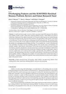
essence of the residual stress distribution in friction stir welds (for example, the location of the peak tensile stress) [11], as these model attempts generally oversimplified the microstructure effects during welding. Unlike single phased materials such as austenitic stainless steel, a material such as heat-treatable Al alloy and high-strength steels usually exhibits profound microstructure changes during welding. The resultant microstructure and mechanical property in the weld region are highly heterogeneous, and highly dependent on the welding process conditions. In order to accurately simulate the residual stress field in these alloys, the analysis must include adequate prediction of the microstructure and property evolution in the weld region as a function of welding process condition. In this study, we present an integrated thermal-metallurgical-mechanical model to analyze the microstructure changes and their effects on the residual stress distribution in friction stir welds of heat-treatable aluminum alloy Al6061-T6. The predictions were compared with various experimental results from previous studies. This integrated approach can be used to quantify the effects of welding process conditions on the residual stress and microhardness distributions in the friction stir weld. MATERIAL, WELDING AND RESIDUAL STRESS MEASUREMENT 305x152x6.35-mm (12x6x¼-in) Al-6061-T6 plates were friction stir welded in the butt joint configuration. The welds were made with two welding speeds, at 280 and 787 mm/min (11 and 31 inch/min) respectively. The rotational speed was kept at 1250 rpm. The diameters of the shoulder and the pin were 19 mm, and 6.35 mm respectively. All other key welding parameters (rotation speed and tool geometry, plunge depth) were kept the same in this investigation. The welds were made in position control mode – the plunge depth of the tool relative to the Al plate was kept the same during a welding run. Such experimental design isolated the effects of welding speed (and the associated heat input change) from other process variables. As shown in Figure 1, the weld started about 15-mm from the left edge of the plate, and stopped about 30-mm from the right edge. The welded plates were then cut to 200x200m (8x8-in) square plates for neutron diffraction residual stress measurement. The remaining part of the welded plates was used for metallurgical examinations. Optical microstructure examinations were conducted on crosssections of friction stir welds. No defects were observed in any of the welds. Vickers microhardness profiles were taken at mid-depth of the cross-section welds with 200-g load [12,13]. Details on welding, microstructure characterization, and peak temperature measurement can be found in [12]. The residual stress measurements were conducted at the High Flux Isotope Reactor of Oak Ridge National Laboratory using a modified triple-axis spectrometer. Details of the neutron diffraction residual stress study have been reported previously [14]. The residual stress measurements were along a cross-section near the middle length of the weld, as marked in Figure 1. The residual stresses were determined as function of position across the weld using a 2x2x2 mm3 sampling volume. The measurements were made at mid-depth and ±1.5 mm away from the mid-depth. Both the advancing and retreating sides of the weld were measured to investigate the effects of material flow driven by the rotating tool. Overall, the neutron diffraction measurement shows minimal depth dependency of the residual stress. In addition, no apparent asymmetry was observed with respect to the weld centerline, indicating that the effect of asymmetric material flow induced by the rotating tool is not obvious for the two specimens under investigation.
Residual stress measurement plane
Welding direction
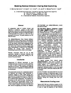
Figure 1 Appearance of friction stir weld and locations for residual stress measurement. MODELING The sequentially-coupled thermal-metallurgical-mechanical finite element modeling approach was used to simulate heat flow, microstructure evolution, and residual stress formation during the friction stir welding process. In this approach, the analysis procedure is divided into two major steps. First, a transient nonlinear heat flow analysis is performed to determine the temperature distribution in the entire weldment for the entire welding and cooling cycle of the process. In the second step, using as input the thermal history from the heat flow model and the composition of the Al alloy, the metallurgical model computes the gradient of microstructure constituents, the associated hardness, yield strength, plastic flow stress, and the volumetric change in the weld metal and the heat affected zone (HAZ). The computed microstructure and mechanical property information, together with the thermal history, is then used as input in the mechanical elasto-plastic calculation of the stress and deformation in the weldment. The metallurgical calculations were actually performed in the mechanical analysis as part of the material constitutive definition subroutines. The thermal -metallurgical-mechanical simulations of the friction stir welds were performed using ABAQUS, a general purpose finite element code [15], enhanced with several user subroutines. These subroutines were linked with ABAQUS to compute the frictional heat generation at the tool/material interface, and to perform the microstructural evolution calculations to determine the spatial and temporal distribution of the mechanical properties during the welding process. The thermophysical and mechanical properties used in the analysis were temperature dependent. The weld plate was modeled as a three-dimensional half model – the symmetry with respect to the weld centerline was utilized to reduce the model to the symmetric half of the plate for computational efficiency. The symmetry assumption was considered to be reasonable, as indicated by the neutron diffraction residual stress measurement data as well as other experimental data available in the literature. Figure 2 shows the finite element mesh used in this study. Eight-noded brick elements were used to discretize the Al plate. The boundary conditions for the heat flow analysis included the surface heat loss due to natural convection and the heat generation between the tool
shoulder and the workpiece. The surface temperature involved was low – the radiation heat loss would be negligible compared to the conventional heat loss. For this reason, the radiation heat loss was not included in the model. For the mechanical analysis, reduced integration scheme was used. The moving tool shoulder and the backing anvil were treated as rigid contact surfaces that interface with the Al plate under the applied forge load. The rigid tool was prescribed to move along the weld joint line at the welding travel speed. The end of the plate was fixed during welding. In addition, as shown in Figure 2, part of the top surface to the Al plate was also constrained vertically during welding to simulate the clamping effects. Both the end constraint and the top-surface claming were released after the weld was cooled down to the ambient temperature, to obtain the as-welded residual stress field. The contacts between the tool and plate and between the anvil and the plate were also removed after the weld is cooled. The final step in the mechanical analysis was to simulate the natural aging process.
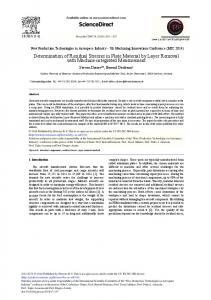
6.35x152x304 mm Figure 2 3-D Finite element model showing the meshed Al plate, the mechanical clamping, the rigid tool and the backing anvil. HEAT GENERATION – The material flow in the stir zone was ignored in the model. Thus, the heat flow was treated as a heat conduction problem. The heat flow model considered the heat generation between the tool shoulder and the workpiece to be the primary heat input mechanism of the FSW process. Such treatment is consistent with other heat flow analyses [16-18], and experimental temperature measurements have shown to be adequate under typical process conditions similar to these studied here [19]. The treatment of the heat generation in this study was based on the fact that metallographic examination of friction stir welds [16] reveals a highly localized heavy deformation layer of material near the shoulder and plate interface, and the HAZ shape of the friction stir weld generally indicates heat transfer in the thickness direction of workpiece, as illustrated in Figure 3. For mathematical convenience, the heat generation in the thin layer near the interface was treated as a surface-heating problem, through use of an interpretive coefficient of friction [17]:
q = ηµpv 2ηµFω = r ; R pin ≤ r ≤ Rsh 2 60 Rsh2 − R pin
(
)
where q is the surface heat flux (W/mm2), F the downward force (N), ω the rotation (rpm), and Rpin and Rsh the radii of the pin and the shoulder respectively (Figure 3). η is the process efficiency that takes account of the heat loss to the tool, and µ the interpretive coefficient of friction. The interpretive friction coefficient was assumed to be unity, based on the torque measurement study [20]. The process efficiency coefficient was difficult to determine. It was adjusted in the model, based on the peak temperature measurement data [12].
ω F
Rsh
Rpin
Figure 3 Heat generation model of friction stir welding. SOFTENING IN HAZ AND WELD – When friction stir welded under hardened conditions, heat treatable Al alloys such as Al6061, can exhibit rather considerable softening in the weld region [4,5,12]. The softening phenomenon in the weld, the thermomechanically affected zone (TMAZ) and HAZ is expected to have considerable effect on the residual stress distribution and therefore must be included in the simulation. In this study, the methodology developed by Myhr and Grong [21] was adapted to predict the phase transformation during welding. The kinetics of the volume fraction changes of the precipitate particles during welding is given by: 1 ⎛ Q + Qs ⎞ 1 ⎜ d ⎞ n1 n n1 ⎟ ⎟ C o 1 Do exp⎜ − ⎟X ⎟ RT ⎜⎜ ⎟⎟ ⎠ ⎝ ⎠ Q ⎛ Q + s ⎞ n1 −1 ⎜ d n1 ⎟ n1 ⎟X = A exp⎜ − RT ⎜⎜ ⎟⎟ ⎝ ⎠
dX n1 ⎛⎜ c1 = dt ro2 ⎜⎝ C p
n1 −1 n1
where X is the normalized fraction of the dissolved precipitate in matrix. The hardness at a given location in the weld region is related to the fraction of the precipitate: Hv = (1 − X )( Hv max − Hv min ) + Hv min
where Hvmin is the hardness in the absence of hardening precipitates (complete reversion), and Hvmax is the base metal hardness after artificial aging treatment (T6 condition). The values of the material constants in the above equations are given in Table 1. Once the hardness data is obtained from the microstructure calculations outline above, the correlations from Cahoon et al [22] were used to estimate the yield strength and tensile strength, to obtain the local mechanical property variations for residual stress calculation. Table 1 Material constants for Al6061 used in this study Material Constant Hvmin Hvmax Qd Qs n A
Value 43 VPN 110 VPN 130 kJ/mol 30 kJ/mol 0.5 8.83865x10⁵
RESULTS AND DISCUSSIONS Heat Flow Figure 4 and Figure 5 show the predicted temperature distribution in the Al plate when the welding was half-way done, for the lower welding speed case (280 mm/min). As the moving tool and the stationary back anvil were treated as rigid surfaces in the analysis, they were excluded from the heat flow calculations and shown in grey color in Figure 4. Due to the mechanical forging action from the tool, the indentation on the plate surface behind the moving tool is apparent in Figure 5. As shown in the figure, the maximum temperature in the plate was near the top surface, reaching approximately 845K that is about 10 degrees below the solidus temperature of Al6061 [23]. The predicted peak temperature is within the generally accepted temperature range in the stir zone of the weld. Figure 6 compares the predicted peak temperatures with the experimentally measured results from Ditzel [12] that were taken under the same welding conditions used in this study. Ditzel only reported the peak temperature for the low welding speed case (280 mm/min). The measurement was done at the middle depth of the plate, using thermocouple attached to predrilled holes. Very good agreement was obtained. Therefore, the heat flow model was able to capture the transient temperature field during friction stir welding of Al6061.
Figure 4 Overall temperature distribution in the FSW Al plate. Welding speed: 280 mm/min, Temperature in Kelvin.
Figure 5 Exposed view of temperature field near the moving tool, with the tool and supporting anvil removed from the view. Welding speed: 280 mm/min, Temperature in Kelvin. 800 Experiment
750
FEM
700
Temp (K)
650 600 550 500 450 400 0
5
10
15
20
25
Distance from Weld Centerline (m m )
Figure 6 Peak temperature distribution at the middle plane as function of distance from weld centerline. The experiment data was taken from [12] under the same welding conditions.
Property gradient Figure 7 shows the predicted Vickers hardness distributions under the as-welded condition and after nature aging. The model captures the complete softening upon completion of welding, as well as the partial recovery of strength in the stir zone as result of the natural aging. Direct comparisons with microhardness measurement data are shown in Figure 8, for both welding speeds studied. The as-welded microhardness was not measured for the high welding speed case. Good agreement between the prediction and the measurement were obtained for both welding speed cases.
Figure 7 Sectional view of the predicted Vickers hardness distribution in the weld. Welding speed: 280 mm/min. Left: as-welded condition, right: after naturalaging. 130 120 110 Hv (500g)
Naturally aged
As-welded
Naturally aged
100 90 80 70
As-welded 60 -20
-15
-10
-5
0
5
10
15
20
Distance from Weld Center (mm)
Figure 8 Comparison of transverse microhardness results at the mid-depth of the plate. Dots indicate measurement data and lines show the predictions. Left: 280 mm/min welding speed (measurement data after Ditzel [12]); Right: 787 mm/min. Residual stress Comparisons between the calculated residual stresses and the neutron diffraction measurement results are given in Figure 9. The comparisons are made at the mid-depth of the plate. The estimated standard deviation of neutron diffraction measurement uncertainties was approximately 15MPa [9]. For valid comparison, the welded plate was cut into a 200x200-mm square in the model, as the case in the neutron diffraction measurement. Overall, the predictions compared well with the neutron diffraction results. Due to the softening of the weld region, the peak tensile stresses are located outside the stir zone. The reduction of the tensile residual stress in the weld center region is quite noticeable. These features were well captured by the finite element model.
S33
250
Stress (MPa)
200
S11 ND
ND
FEM
FEM
150 100 50 0 -50 -100 -100
-50
0
50
100
Distance (mm) S33
S11
250
Stress (MPa)
200
ND
ND
FEM
FEM
150 100 50 0 -50 -100 -100
-50
0
50
100
Distance (mm)
Figure 9 Comparison of residual stresses. The top plot shows the low welding speed case, and the bottom plot shows the high welding speed case. ND: neutron diffraction measurement data, FEM: finite element simulation results; S33: longitudinal stress, S11: transverse stress. The overall as-welded residual stress distributions in the entire plate are shown in Figure 10 for the high-welding speed case. Figure 11 presents the close-up cross-sectional views of the same residual stress field. The location of the cutting plane for the cross-sectional view is depicted in Figure 10, corresponding to the neutron diffraction measurement plane shown in Figure 1. Consistent with the neutron diffraction measurement results, the finite element modeling results reveal that the longitudinal residual stress is the predominant residual stress component in the weld. The transverse residual stress is considerably smaller in magnitude in the entire welded region, although relatively high compressive residual stress develops outside both ends of the weld. The residual stress in the through-thickness direction is nearly negligible when compared with the other two stress components. It is important to note that there was a noticeable stress reduction when the welded plate (305x305mm) was cut into 200x200mm square for the neutron diffraction measurement. This can be seen by comparing Figure 9 and Figure 11 for the high welding speed case. The peak value of the longitudinal residual stress was dropped from about 235MPa in the aswelded plate to about 200MPa after the cutting. Thus, a 200mm long friction stir weld may not be representative of the true residual stress state in a longer structure weld.
Figure 12 shows the longitudinal stress of the low welding speed case. A comparison with the high welding speed case in Figure 11 clearly revealed the effect of welding speed on the residual stress. Overall, the low heat input associated with the high welding speed results in higher tensile residual stresses in the weld region. On the other hand, the position of peak tensile residual stress is closer to the weld centerline. This can be explained by the less HAZ softening in Al6061-T6 in the high welding speed case (Figure 8). The computational analysis in this study also reveals that, while the natural aging process causes considerable increase in the hardness (and mechanical strength) in the stir zone and TMAZ, it has minimal impact on the residual stress field. This can been seen by comparing the longitudinal residual stress field after the natural aging shown in Figure 13 with that of the as-welded case in Figure 12. The two residual stress fields are nearly identical. While this appears counter-intuitive, it can be explained from the theory of solid mechanics: an increase in the mechanical strength would not necessarily require a rebalance of the stress field that is already under equilibrium. In this aspect, the residual stress field in Al6061 friction stir weld would be controlled by the as-welded material property distribution. This finding would lead to novel approaches for residual stress management and optimization in friction stir welds of heat treatable Al alloys.
Figure 10 As-welded residual stresses for the higher welding speed case (787 mm/min). Top: longitudinal residual stress, bottom: transverse residual stress.
Figure 11 Cross-section view of the residual stress field under as-welded condition. The cross-section cutting plane is illustrated in Figure 10, corresponding to the plane where the neutron diffraction measurement was conducted. Welding speed: 787 mm/min. Top: longitudinal stress, middle: transverse stress, bottom: through-thickness stress. Stress in MPa.
Figure 12 Cross-sectional view of longitudinal residual stress field in the low welding speed case. Stress in MPa.
Figure 13 Cross-section view of longitudinal residual stress after natural aging. Welding speed: 280 mm/min. Stress in MPa. Effects of Property Gradient on Mechanical Performance of Weld Joint The integrated thermo-metallurgical-mechanical modeling approach presented in this study makes it possible for realistic simulation of the performance of a friction stir weld during subsequent mechanical loading in service. Although performance simulation of weld joint is still a subject requiring considerable development, recent attempts have shown the potential of integrated modeling approach [24]. As an example, the transverse weld tensile test was simulated here to illustrate its potential application to Al friction stir weld. The testing case was from the low welding speed case. Using the element removal procedure in ABAQUS, the entire welded plate was reduced into a 25-mm wide and 200-mm long tensile test bar that is commonly used for friction stir weld. In this “virtual” tensile test bar, the details of the material property gradient in the weld region as the result of welding operation were retained. In addition, the residual stress field was naturally re-balanced as part of the element removal process. Figure 14 and Figure 15 show, respectively, the distribution of yield strength and the residual stresses in the tensile bar before the tensile testing. It is important to note that the welding residual stress is not completely relieved in the 25-mm wide tensile test specimen, although it magnitudes are significantly reduced. The deformation sequence during the tensile testing is presented in Figure 16, represented by the total transverse strain. Due to the softening and residual stress in the HAZ, the transverse
tensile loading leads to localized deformation, necking and eventual failure in the HAZ of the weld. The integrated model provides a detailed account of the evolution of the deformation process. The predicted failure location was in the HAZ, matching very well with the actual weld failure location experimentally observed [12] as shown in Figure 17.
Figure 14 Yield strength distribution in transverse weld tensile test bar.
Figure 15 Longitudinal residual stress (top) and transverse residual stress (bottom) in the transverse weld tensile test bar before tensile testing. Stress in MPa.
Figure 16 Simulation of the deformation sequence during transverse weld tensile test. Color contour plots show the magnitude of transverse total strain field.
Figure 17 Failure location of actual friction stir weld in transverse weld tensile test (after Ditzel [12]).
CONCLUSION An integrated thermal-metallurgical-mechanical finite element modeling approach was applied to investigate the effects of welding process conditions on the microstructure evolution and the formation of residual stresses in friction stir welded Al6061-T6 plate. Experimental data from previous studies confirmed the validity of the model. The finite element modeling results revealed tensile residual stresses in both the transverse and longitudinal directions in the weld region. However, the longitudinal stress was the predominant residual stress component in the weld. The peak tensile longitudinal residual stress is located in the HAZ, approximately corresponding to tool shoulder imprint on the plate surface, and is lower than the yield strength of the base metal. The residual stress distribution is strongly dependent on the welding speed. The high heat input associated with low welding speed leads to more profound softening in the weld region. This in turn results in overall reduction in magnitude of the longitudinal residual stress, but a wider tensile stress zone. The residual stress field is governed by the as-welded yield strength distribution in the stir zone, HAZ, and TMAZ of the friction stir weld joint. On the other hand, the natural aging process, while strongly affecting the weld strength, exhibits minimal influence on the residual stress. The integrated model can be further used to effectively predict the performance of the welded structures under various service loading situations. ACKNOWLEDGMENTS
The authors are grateful of Dr. J.E. Gould and Dr. T.J Lienert of Edison Welding Institute, in providing the weld specimens used in this study. This research was sponsored by the U.S. Department of Energy, Assistant Secretary for Energy Efficiency and Renewable Energy, Office of FreedomCAR and Vehicle Technologies, as part of High Strength Weight Reduction Materials Program, and by the Division of Materials Sciences and Engineering, under Contract DE-AC05-00OR22725 with UT-Battelle, LLC. Neutron diffraction measurements were made at the High Flux Isotope Reactor, operated with the support from U.S. Department of Energy, Office of Basic Energy Sciences. REFERENCES
1 2 3 4 5 6 7
W.M. Thomas, Int. Patent Appl. No PCT/GB92 Patent Application No.9125978.8, (1991). C.J. Dawes and W.M. Thomas, Welding Journal, 75(3), 41-45 (1996). S. Kallee and D. Nicholas, SAE Technical Paper No 982362, (1998). K.J. Colligan, P.J. Konkol, J.J. Fisher, and J.R. Pichens, Welding Journal, 82(3), 34-40 (2003). J.E. Gould, T.J. Linnert, and Z. Feng, SAE Technical Paper 981875 (1998). Y.S. Sato and H. Kokawa, Metall. Mater. Trans. A 32A(12) 3023-3031 (2001). G. Bussu, and P. E. Irving, "The role of residual stress and heat affected zone properties on fatigue crack propagation in friction stir welded 2024-T351 aluminium joints." International Journal of Fatigue v25, 77-88 (2003).
8 9 10 11 12 13 14
15. 16 17 18 19 20 21
22 23 24
M. James, M.W. Mahoney, and D. Waldron, 1st Int. Symp. Friction Stir Welding, Thousand Oaks, California, USA, June 14-16 (1999). X.-L. Wang, Z. Feng, S.A. David, S. Spooner and C.R. Hubbard, 6th Int. Conf. Residual Stresses, Oxford, UK, July 10-12 (2000). C.D. Dalle, E. Lima, J. Wegener, A. Pyzalla and T. Buslaps, 3rd Int. Symp on Friction Stir Welding, Kobe Japan, Sept 27-28 (2001). Y.J. Chao and X. Qi, J. Mat. Processing and Manufacturing Science, 7(2), 215-233 (1998). P.J. Ditzel, “Microstructure/property relationships in aluminum friction stir welds,” MS Thesis, The Ohio State University, Columbus, OH (1997). T.J. Lienert and J.E. Gould, Unpublished Research, Edison Welding Institute (1998). X-L. Wang, Z. Feng, S.A. David, S. Spooner, and C.R. Hubbard, “Neutron Diffraction Study of Residual Stresses in Friction Stir Welds,” 6th Int. Conf. Residual Stresses, IOM Communications, London, United Kingdom, 1408-1414, (2000). ABAQUS/Standard version 5.8 Theory Manual. Hibbit, Karlsson & Sorensen Inc. Pawtucket, Rhode Island, USA, 1999. Z. Feng and J.E. Gould, EWI Research Report (1996). Z. Feng, J.E. Gould and T.J. Lienert, Hot Deformation of Aluminum Alloys (eds. T.R. Bieler et al.), 149-158 (1998). O. Frigaad, O. Grong, and O.T. Midling, 7th Int. Conf. Joints in Aluminum, Cambridge, UK, April 16, 1998. J.C. McClure, Z. Feng, T. Tang, J.E. Gould, L.E. Murr and X. Gao, Trends in Welding Research (eds, S.A. David et al.), 590-595 (1998). Z. Feng, and M.L. Santella, Unpublished research, Oak Ridge National Laboratory (2003). O.R. Myhr, and O. Grong, "Process modeling applied to 6082-T6 aluminum weldments. Part 1: Reaction kinetics. Part 2: Applications of model." Acta Metal 39(11): 2693-2708, (1991) J.R. Cahoon, W. H. Broughton, and A. R Kutzak, "Determination of Yield Strength from Hardness Measurements." Metallurgical Transactions 2(7): 1979-1983, (1971). ASM International, “Properties of Wrought Aluminum and Aluminum Alloys,” Metals Handbook Vol 2, www.asminternational.org/hbk Z. Feng, S. S. Babu, et al. "Modeling of Resistance Spot Welds -- Process and Performance." Welding in the World, 45(11-12): 18-24 (2001).