1st International Conference on Sensing Technology November 21-23, 2005 Palmerston North, New Zealand
Do we really need sensors? A Sensorless Magnetic Bearing Perspective Dr. S. C. Mukhopadhyay College of Sciences, Massey University, Palmerston North, New Zealand Email:
[email protected]
Abstract Usually magnetic bearing consists of an actuator and a levitated object which can be either the rotor of a motor or any other ferromagnetic body. For proper function and to provide stable support, the actuator needs an accurate information about the position of the levitated body which must be given by a sensor. In many applications the displacement sensor with associated wires and cost to be avoided resulting in displacement sensorsless magnetic bearing. This paper has discussed different design issues regarding sensorless control of magnetic bearing system to answer the question “Do we really need sensors?”.
Keywords: Magnetic bearing, sensorless control, displacement sensors, controllability and observability. 1
will explore different design issues involved with the sensorless control of magnetic bearing system.
Introduction
The magnetic bearing systems used in high speed rotating machines have got many advantages compared to mechanical bearings. They are long life, frictionless and lubrication free operation, feasible operation at high speed etc. In magnetic bearing system the rotor is levitated in the magnetic field. The magnetic bearing system can be either of two types: (i) Active magnetic bearing in which all are electromagnets and (ii) Hybrid magnetic bearing in which a combination of electromagnets and permanent magnets (PM) are used. In hybrid type magnetic bearing system usually the rotor is levitated by the repulsive forces between stator and rotor permanent magnets [1, 2, 3]. The magnetic bearing systems in general are unstable in nature. The controlled electromagnets are used to keep the rotor in the desired position. Gap sensors are used to determine the position of the rotor. Usually good quality sensors are expensive, need space for installation. So to design and fabricate magnetic bearing system without using sensor and achieve control is another approach. In this approach instead of using gap sensors the gap information are derived by some computation technique from the measurement of current. The current is dependent on the inductance which in turn is a function of the gap distance. So it is possible to design and fabricate a magnetic bearing system and stabilise without using any external sensors. This paper will try to answer the question answered in the title. The rest of the paper
2 Sensors for Magnetic Bearings Usually magnetic bearing consists of an actuator and a levitated object which can be either the rotor of a motor or any other ferromagnetic body. For proper function and to provide stable support, the actuator needs an accurate information about the position of the levitated body which must be given by a sensor. The position sensors for magnetic bearing applications are associated with the following characteristics: i) operation must be non-contacting, ii) sensors need to be durable, stable and affordable, iii) bandwidth of the sensor should be larger than that of the amplifier and bearing, iv) usually expensive for good performance, v) generally it is difficult to maintain their alignment in the bearing gap, vi) some of the sensors also require sophisticated electronics for excitation and hence separate power source. Other than the above mentioned characteristics the technical characteristics of the sensors such as the phase shift between in and outgoing signals, frequency response, dc-stability, temperaturestability, resolution, and stability to external emf interference are very important. The types of sensors
425
1st International Conference on Sensing Technology November 21-23, 2005 Palmerston North, New Zealand used in magnetic bearing applications can be any of the following types [4]: i. ii. iii. iv. v. vi. vii.
Eddy current Inductive Capacitive Optical Hall element Ultrasonic Laser.
Eddy current sensors are the most widely used one for the magnetic bearing application [4]. It has the characteristics of small physical size with high resolution, excellent temperature stability, small phase shift and high dc stability. Capacitive sensors even though exhibit a higher resolution and better temperature and dc stability but they are bigger in size and suffer from environmental changes. Usually the size of opto-sensors are very large and are influenced by outside temperature but they are very fast. Hall sensors are very small in size but suffer from temperature instability and are slow. Ultrasonic sensors have limited use for poor resolution.
3 Sensorless Control Usually a magnetic bearing system is stabilised using a position sensor for the gap information. Since it is easier to design a controller with position measurement, the position of the rotor is the most popular parameter for feedback. But sensors are expensive, need space for installation, difficult to maintain their alignment with time and also the wiring involved with sensors may create reliability problem. The development of magnetic bearing systems without using position sensors are described in this section. 3a Literature survey A lot of technical articles have been reported on selfsensing active magnetic bearings (AMB) but only a few have been discussed here. Vischer and Bleuler reported the self-sensing AMB [5]. By self-sensing AMB they meant an AMB in which a gap sensor is replaced by a simple current measurement in the amplifier. The concept of the selfsensing AMB results in a significant reduction of hardware effort but also increases the complexity of the software. Though experimental results have been reported in the paper but not much has been said about the current measurement. Matsuda, Okada and Tan have proposed the pulse width modulated (PWM) type self-sensing method [6]. The electromagnet is driven by PWM signal. The carrier component of the coil current has a displacement information. The gap displacement information is estimated by using a resonant circuit
and a low pass filter. The drawback of this method is the limitation of the linear range. In [7] Matsuda, Okada and Tani have proposed a new type self-sensing magnetic bearing by using the principle of differential transformer using a push-pull type electromagnet. Using two kinds of coils, one for bias current and another for control current for the differential transformer, it is possible to estimate the displacement information of the shaft from the PWM carrier component of the control current. Sivadasan [8] has explained the operating principle of inductance sensing method for the working of a selfsensing active magnetic bearing. It is possible to have a linear relationship between inverse of the coil inductance and the bearing gap. To identify and quantize the limiting factors affecting the inductance measurement, a real AMB under working conditions has been simulated using Finite Element Analysis (FEA) techniques. The effect of the rotor induced eddy current has not been taken into the analysis. No experimental results have been reported in the paper. Mizuno et. al. [9] has analyzed the controllers designed for position-sensorless voltage-controlled active magnetic bearing from stabilization view point. It has been shown that full-order and reduced-order observer-based stabilizing controller differs in stability; any reduced-order observed-based stabilizing controller is always unstable while most of the full-order observer-based stabilizing controllers are stable. It has also been reported that the full-order observer based stabilizing controller is destabilized by a modification including the effect of eddy current flowing through the cores of the electromagnet. In [10] Mohamed et. al. has presented a complete model of four radial degree of freedom self-sensing magnetic bearing systems including all interactions between different degrees of freedom. The method has utilized Q-parameterisation theory and has included unbalance compensation. The simulation results have been presented. Morse et. al. [11] has compared robustness limits for a magnetic bearing system controlled using two configurations; position and current measurement and current measurement only i.e., the self-sensing bearing. It has been concluded that the self-sensing magnetic bearing configuration, although lower in cost and simpler to build, suffers from lower robustness to uncertainties in the system. The analysis and experimental results for a homopolar magnetic bearing system that uses the same coils to stabilize the rotor and sense its position has been reported in [12]. The linear range of the bearing system is ± 0.1 mm which is very limited in practical application. In [13] Komori and Shiraishi have described the development of a superconducting magnetic bearings assisted by self-sensing active magnetic bearings based on the principle of a differential transformer. The differential transformer provides a linear voltage
426
1st International Conference on Sensing Technology November 21-23, 2005 Palmerston North, New Zealand output for a rotor displacement of ± 0.3 mm, which is used to control the rotor. Yin et. al., [14] have proposed Sensorless position control of active magnetic bearings based on high frequency signal injection method. The position information of the suspended body has been extracted from the coil currents, which contain high frequency voltage without any additional hardware. More researches are required to improve the dynamics of the controller to perform sensorless control. In [15] the analysis of an electrodynamic suspension system for maglev vehicles has been presented in which the active damping of the vertical oscillations has been obtained without position, velocity and acceleration transducers. The damping effect has been accomplished controlling the supply voltage of the damping coil to respond to current changes due to vertical oscillations. The simulations results corresponding to step response and ride quality have been presented. The realization of a self-sensing magnetic bearing without employing separate position sensors based on the estimation of gap position has been described in [16]. To extract the gap information the current signal is demodulated using a filter. The forward path filter produces reliable position estimation only when the duty ratio of the amplifier is fixed. The introduction of a simulated bearing model and a servo-controller for the inductance of the coil substantially improves the position estimation in terms of accuracy and bandwidth. 3b Theory of Position Sensorless Control Usually sensors are expensive and associated with wires which may be a problem in many applications. Due to these problems a lot of efforts had been put into to eliminate the position sensors from the bearing assembly. But for the stable operation of the system the gap information is essential. So the magnetic bearings which estimate the rotor position from information in electromagnet’s signals are referred to as “self-sensing” or position sensorless magnetic bearing. The benefits obtained by eliminating the position sensors are: i) reduction of hardware cost of the system, ii) the elimination of position sensors enables a simple construction without sensor housing and cables, iii) without sensors the mechanically optimized construction enables to design a more rigid rotor with higher natural frequencies, iv) removing the potential failure of the sensing element improves the system reliability. The underlying principle of sensorless control is to measure the inductance of the electromagnet coil of the magnetic bearing assembly. The inductance is
inversely proportional to bearing gap. This is shown below: The current flowing through the electromagnet produces magnetic flux. The total number of flux linking the coils is given by ψ = N φ ; N is the number of turns of the electromagnet, φ is the flux produced by the electromagnet and ψ is the flux-linkage. Assuming the reluctance of the iron path is zero, the flux produced by the electromagnet φ is given by, Ni µ 0 Ag Ni ; ℜ g is the reluctance of the air φ= = 2*ℜg
2x
gap of the electromagnet as shown in figure 1, i is the current flowing through the electromagnet, x is the gap distance and Ag is the area of the gap. Which means ψ =
N 2 i µ 0 Ag
2x
.
Air Gap Figure 1: The electromagnet and the gap distance
The inductance of the electromagnet is thus given by, N 2 µ 0 A g ; So the inductance of the ∂ψ L = = ∂i 2x electromagnet coil is inversely proportional to the gap distance. The measurement of inductance based on the injection of a high frequency test signal to the electromagnet coil has been considered here. A small known test signal of constant amplitude is superimposed to the coil to cause a high frequency current to flow through the coil. This is on the assumption that the high frequency current being of a low magnitude will not affect the performance or stability of the system. An external small resistance is connected in series with the electromagnet and the voltage across the resistance is measured. Mathematically we can write Vm sin ωt = ( R + r + jω L) I m sin(ωt − θ ) ; Vm is the peak value of the test signal, R and L are the resistance and inductance of the coil, r is the external series resistance, Im is the peak value of the high frequency current and θ is the phase angle of the current. For a large ω, ωL >> (R+r), so the peak voltage across the external series resistance can be written as
V p = rI m ≅
rVm 2 rVm x = = Kx where ω L ωµ 0 N 2 Ag
constant K is given by K =
427
2 rVm . ω µ 0 N 2 Ag
the
1st International Conference on Sensing Technology November 21-23, 2005 Palmerston North, New Zealand So the gap can be determined by measuring the peak voltage of the high frequency component across the external resistance.
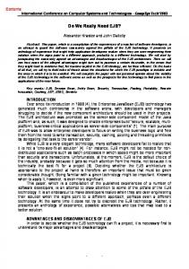
4 Modeling Of the Bearing System Assuming the fabricated and developed system as shown in figure 2 is to be controlled under sensorless environment, the modelling of the system under sensorless control can be derived as follows:
Electromagnet
Permanent Magnet Upper bearing
The force developed by the PM set as a function of gap distance can be expressed as FPM = FPMO − k PM x ; FPMO is the force at nominal operating point, x is the deviation of gap distance from the nominal operation and kPM is the forcedisplacement factor for the PM. The force generated in the electromagnet is given by 2
I Fe = K e ; Ke is obtained from the design X parameters of the electromagnet. Assuming the nominal current and gap displacement as Io and Xo and the deviations are i and x, the linearized equation for the electromagnetic force can be written as Fe = Fe 0 + ki i + k x x ; Fe0 is the force at nominal
operation, ki is the force-current factor and kx is the force displacement factor for the electromagnet. At nominal operation, Fe0 + 2 FPM0 = Mg. The dynamic equation is written as d2x M 2 = (k x − 2k PM ) x + ki i . dt The relationship between current and voltage of the electromagnet coil is given by
Gapsensor
Lower bearing
U = RI +
dψ ; U is the applied voltage to the coil. dt
Figure 2: The fabricated hybrid magnetic bearing system
At nominal operation, U0 = RI0 and the nominal value 2 of flux-linkage is given by ψ = N I 0 µ 0 A g 0 2X
For the Hybrid Magnetic Bearing (HMB) system as shown in figure 2 the rotor is supported by the repulsive forces due to two sets of permanent magnet bearings as shown in figure 3 and a portion is supported by the force generated in the electromagnet.
and ψ 0 = L0 I 0 where L0 is the nominal value of inductance. With a deviation of voltage, u from the nominal condition, the equation can be written as
0
Aluninum disk
u = Ri +
Permanent magnet ψ 0 +ψ =
ψ≈
dψ ; dt N 2 ( I 0 + i ) µ 0 Ag 2( X 0 − x)
ψ0
i+
ψ0
= ψ 0 (1 +
x = L0i +
i x −1 )(1 − ) I0 X0
ψ0
x. X0 di ψ 0 dx + . So we get, u = Ri + L0 dt X 0 dt So,
I0
X0
Based on the above derivation the state space equation of sensorless bearing can be written as
dx dt 0 1 0 x 0 ki dv = kx − 2kPM 0 v + 0 u dt M M i 1 ψ R di 0 0 − − L0 L0 X0 L0 dt
Figure 3: Two disks with 24 magnets in both form a magnetic bearing
So the dynamic equation is written as d2X M = Fe + 2 FPM − Mg ; M is the mass of the dt 2 complete rotor system, Fe is the force generated by electromagnet, FPM is the force developed by one set of PMs and g is the gravitational constant.
where v = dx/dt, the translational velocity.
428
1st International Conference on Sensing Technology November 21-23, 2005 Palmerston North, New Zealand
The output equation is given by
x y = i = [ 0 0 1] v . i The system is observable and controllable. So from the information of current, the gap displacement can be realized and the system can be controlled. The current system has been simulated with this approach and stable performance has been obtained. An observer based simulation model has been designed as shown in figure 4 and the result of rotor vibration is shown in figure 5. It is seen that the rotor reaches steady state position and is stabilised. The response of the bearing system for a step input with sensor based control is shown in figure 6. The controller takes the information from the displacement sensor and uses it to achieve stability. While the response of the sensorless control as shown in figure 5 is compared with that of figure 6, it is seen that the time to reach stability is significantly large for sensorless control compared to time with using position sensor.
Figure 4: Observer based simulink model of Sensorless magnetic bearing system
Figure 5: The simulated rotor vibration for sensorless control
Figure 6: The actual rotor vibration based on sensor
5 Practical Design Issues and Requirement of Sensors The determination of gap information from the injection of high frequency signal to the coil of HMB is based on the following assumptions: The permeability of the iron core is i) infinite which means the MMF drop across the iron core is zero, The permeability of iron core remains ii) infinite with time, The permeability of iron core is iii) independent of the change of the gap distance, The effect of rotor induced eddy current iv) on the coil inductance is negligible, The effect of finite and non-linear v) magnetic property of iron, as well as the influence of electromagnet coil current on the inductance is negligible, The bearing gap distance doesn’t change vi) its regular shape when the rotor moves back and forth, The leakage and fringing of magnetic vii) flux is negligible. In the following part the effect of the magnetic permeability of the core on the inductance of the coil are examined. It is known that the relative permeability of all magnetic materials is finite. The superpermalloy and other such materials possess a very high relative magnetic permeability but they are really very expensive. In order to fabricate a system comparable with the cost of the gap sensor, normally available ferromagnetic iron is used to make the electromagnet. They exhibit an unsaturated relative permeability of around 3000. In the fabricated system a very cheap material mild steel has been used for the electromagnet and its relative permeability is slightly higher than 1000. The design details of the fabricated electromagnet are as follows: Number of turns, N = 720, Mean length of flux path, li = 200 mm, Core area perpendicular to flux path, Ai = 314 mm2,
429
1st International Conference on Sensing Technology November 21-23, 2005 Palmerston North, New Zealand
Nominal air gap length, lg = 2 mm, Nominal current of the electromagnet, I = 1 A. It is assumed that the air gap area is equal to the core area. Assuming the relative magnetic permeability as 1000, the nominal inductance is calculated as follows: The magnetic reluctance of the air gap at nominal operating condition is given by
Rg =
1 lg = 5.07 E + 6 A/Wb, µ0 Ag
The magnetic reluctance of the core is given by
Ri =
lg
1
µ0 µr Ag
= 0.507 E + 6 A/Wb.
The nominal inductance is thus given by,
L0 =
N2 = 92.95 mH. Rg + Ri
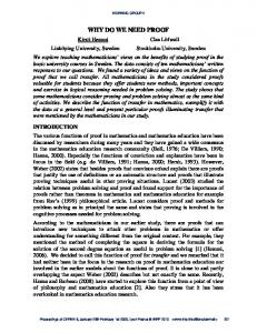
The inductance has been measured experimentally and found to be 68.1 mH. This is very close to the theoretical calculation. The difference is due to the actual working permeability is slightly less to that of the calculated one. Assuming the magnetic relative permeability of the core material remains same, the variation of inductance as a function of gas distance for two different values of relative permeability is shown in figure 7. 0.45 0.4
Inductance (H)
0.35 0.3 Relative permeability
0.25 0.2
1000
0.15
250
0.1 0.05 0
0.5
1
1.5 2 Gap distance (mm)
2.5
3
Figure 7: The variation of inductance with air gap
It has been seen in the theoretical derivation that the inductance is inversely proportional to gap distance. This is true if the magnetic permeability is really very high so that the reluctance of the magnetic circuit can be neglected with respect to the reluctance offered by the air gap. With the decrease of magnetic permeability of the core this assumption is not valid and the change of inductance is less as is shown in figure 7. In order to use this material for the sensorless design a knowledge of the characteristics is required and is to be stored in the software. It is well known that the properties of magnetic materials change with time [17] and the software data to be updated with time.
The other assumptions taken in the design of Sensorless control have also considerable effect on the system. Another important factor to be discussed here is the relative magnitude of the high frequency with respect to normal signal. The assumption used for the measurement of gap information is that the coil reactance is much larger than the resistance at the frequency of test signal. The electromagnet used in the fabricated system has a coil resistance of approximately 12 Ω and a series resistance of 0.1 Ω is used to measure the gap information. If the frequency of the injected signal is 1 kHz, the reactance corresponding to a coil inductance of 75 mH is approximately 50 Ω . This reactance value is not very large compared to 12.1 Ohm resistance. If a high frequency injected voltage signal taken as 1 mV, this will produce a voltage approximately 1.8 µV across the series resistance. Since the nominal current is around 1 A, the voltage corresponding to this current is 0.1 V. So the signal corresponding to high frequency signal of 1.8 µV will be superimposed with 0.1 V signal. From this mixture to filter out 1.8 µV high frequency signal may not be impossible but it is a real challenge to the designer. The next challenge is the change of the magnetic permeability of the core with time. It is assumed that the permeability of the core doesn’t change with time. But in practical situation the magnetic property deteriorate with time [17]. The system shown in figure 2 has been fabricated three years back. At that time the performance was quite good. After three years of operation the inductance changes between 82 mH to 60 mH for a minimum airgap to an infinite airgap. This mean the relative permeability of the core has gone down to a very low value. Using the signal from the gap sensor the operation of the bearing system is carried out without any problem. But with this change of magnetic property of the core, the operation of the bearing system under sensorless environment seems to be very difficult but the system works fine with a displacement sensor. The change of magnetic property with time is impossible to avoid for costly and very high quality materials too. The other problems associated with the sensorless design are as follows: 1) The test signal generator must be produced and added with the power amplifier, 2) Additional analog filter circuit is required in order to extract the high frequency component voltage signal across the series resistance. This increases the requirement of system components, therefore decreases the system reliability. Even though it is feasible to design sensorless control but different practical design issues are to be considered before to go for it. If space requirement for the sensor is not a real issue, the control with
430
1st International Conference on Sensing Technology November 21-23, 2005 Palmerston North, New Zealand
displacement sensor will definitely make life of the designer much easier.
[9]
6 Conclusions This paper has reviewed practical and design issues regarding position sensorless control of magnetic bearing systems. A review of a few literature on sensorless control of magnetic bearing systems has been reported. A hybrid magnetic bearing system based on combination of permanent magnets and electromagnet has been fabricated and developed for a vertical-shaft motor. The unstable magnetic bearing system has been stabilised implementing both analog circuit and microcontroller based controller using the rotor position information from a gap sensor. The principle of operation of the magnetic bearing system without using gap sensor has been described. The fabricated magnetic bearing systems has been simulated under sensorless control based on an observer. If the benefits obtained from Sensorless control are not highly advantageous, the control with displacement sensor will definitely make life of the designer much easier.
[2]
[3]
[4] [5] [6]
[7]
[8]
[11]
[12]
[13]
[14]
7 References [1]
[10]
Mukhopadhyay, S., Ohji, T., Kuwahara, T., Iwahara, M., Yamada, S., Matsumura, F., "Comparative Studies of Levitation and Control Performances of Two Types Single Axis Controlled Repulsive Type Magnetic Bearing", NASA periodicals, Vol. NASA/CP-1998207654, pp 393-405, May 1998. Mukhopadhyay, S.C., Ohji, T., Iwahara, M., and Yamada, S., "Design, Analysis and Control of a New Repulsive Type Magnetic Bearing", IEE proceedings on Electric Power Applications, vol. 146, no. 1, pp. 3340, January 1999. Mukhopadhyay, S.C., Ohji, T., Iwahara, M., and Yamada, S., "Modeling and Control of a New Horizontal Shaft Hybrid Type Magnetic Bearing", IEEE transactions on Industrial Electronics, Vol. 47, No. 1, pp. 100-108, February 2000. Boehm, J., Gerber, R., and Kiley, N.R.C., “Sensors for Magnetic Bearings”, IEEE Transactions on Magnetics, Vol. 29, No. 6, November 1993, pp. 2962-2964. Visher, D., and Bleuler, H., “Self-Sensing Active Magnetic Bearing”, IEEE Transactions on Magnetics, Vol. 29, No. 2, March 1993, pp. 1276-1281. Matsuda, K., Okada, Y., and Tan, A.C.C., “PWM Type Self-sensing Magnetic Levitation Control”, Proceedings of the Fifth International Conference on Adaptive Structures, December 1994, pp. 633-642. Matsuda, K., Okada, Y., and Tani, J., “Self-sensing Magnetic Bearing Using the Principle of Differential Transformer”, Proceedings of the Fifth International Symposium on Magnetic Bearings, Kanazawa, Japan, August, 1996, pp. 107-112. Sivadasan, K.K., “Analysis of Self-Sensing Active Magnetic Bearing Working on Inductance Measurement Principle”, IEEE Transactions on
Magnetics, Vol. 29, No. 2, March 1993, pp. 12761281. Mizuno, T., Araki, K., and Bleuler. H., “Stability Analysis of Self-Sensing Magnetic Bearing Controller”, IEEE Transactions on Control Systems Technology, Vol. 4, No. 5, September 1996, pp. 572579. Mohamed, A.M., Matsumura, F., Namerikawa, T., and Lee, J.H., “Modeling and Robust Control of SelfSensing Magnetic Bearings with Unbalance Compensation”, Proceedings of the 1997 International Confernce on Control Applications, October 5-7, 1997, pp. 586-594. Morse, N., Smith, R., Paden, B., and Antaki, J., “Position Sensed and Self-Sensing Magnetic Bearing Configurations and Associated Robustness Limitations”, Proceedings of the 37th IEEE Conference on Decision & Control, USA, Decmber 1998, pp. 2599-2604. Tsao, P., Sanders, S. R., and Risk, G., “A Self-Sensing Homopolar Magnetic Bearing: Analysis and Experimental Results”, Proceedings of the 38th IEEE Conference on Decision & Control, USA, Decmber 1999, pp. 2560-2565. Komori, M., and Shiraishi, C., “A Levitated Motor with Superconducting Magnetic Bearings Assisted by Self-Sensing AMBs”, IEEE Transactions on Applied Superconductivity, Vol. 13, No. 2, June 2003, pp. 2189-2192. Kim, Y.S., Kim, J.H., Sul, S.K., Ahn, H.J., and Han, D.C., “Sensorless Position Control of Active Magnetic Bearings Based on High Frequency Signal Injection Method”, Eighteenth Annual IEEE Applied Power
Electronics Conference and Exposition, 2003. APEC '03 Volume 1, 9-13 Feb. 2003 pp. 83 – 88. [15] Brunelli, N., Casadei, D., Serra. G, and Tani, A., “Active Damping Control for Electrodynamic Suspension Systems without Mechanical Transducers”, IEEE transc. on Magnetics, Vol. 32, No. 5, pp. 5055-5057, September 1996. [16] Noh, M.D., and Maslen, E.H., “Self-Sensing Magnetic Bearings Using Parameter Estimation”, IEEE Transactions on Instrumentation and Measurement, Vol. 46, No. 1, February 1997, pp. 45-50. [17] Ohji, T., Mukhopadhyay, S.C., Iwahara, M., and Yamada, S., “Performance of Repulsive Type Magnetic Bearing System under Nonuniform Magnetization of Permanent Magnet”, IEEE transc. on Magnetics, Vol. 36, No. 5, pp. 3696-3698, September 2000.
431