Domain Specific Architecture for Next Generation Wireless Communication Botao Zhang, Hengzhu Liu, Heng Zhao, Fangzheng Mo, Ting Chen Institute of Microelectrics & Microprocessor, School of Computer Science National University of Defense Technology, Changsha HN, P.R.China
[email protected] Abstract—In order to solve the challenges in processor design for the next generation wireless communication systems, this paper first proposes a system level design flow for communication domain specific processor, and then proposes a novel processor architecture for the next generation wireless communication named GAEA using this design flow. GAEA is a shared memory multi-core SoC based on Software Controlled Time Division Multiplexing Bus, with which programmers can easily explore memory-level parallelism of applications by proper instructions and scheduling algorithms. MPE, which is the kernel component of GAEA, adopts hybrid parallel processing scheme to explore instruction-level and data-level parallelism. The pipeline and instruction set of GAEA are also optimized for the next generation wireless communication systems. The evaluation and implementation results show that GAEA architecture is suitable for the next generation wireless communication systems.
I.
INTRODUCTION
The next generation wireless communication standards, such as 3GPP LTE [1] and WiMAX [2], are becoming the dominant communication standards. In the opinion of the researchers and engineers in communication domain, software defined radio (SDR) will be thorough applied in next generation wireless communication systems. The main technology of SDR is the digital baseband signal processing based on programmable processors and coprocessors. The bandwidths of next generation wireless communication systems are far greater than the 3G systems, meanwhile most of the next generation wireless communication systems adopt new modulation technologies, such as MIMO and OFDM, resulting in many new issues on architecture design of the processors for SDR applications. First, the peak loads of the next generation wireless communication physical layers are 10 times, even 100 times more than the ones of 3G physical layers. The peak load of the physical layer of 5MHz WiMAX protocol is almost 40Gops, and 20MHz 3GPP LTE protocol is over 200 Gops, far exceeding the computing capability of state-of-the-art processors for SDR applications [3]. Second, the power consumption should not be overlooked in this type of processor. Performance power ratio is always adopted as the metric for performance and power. According to related research, the performance power ratio of the 3G systems should be almost 100Mops/mW [4]; while the number may be much higher for the next generation wireless communication systems. Processors should be more dedicated, more specific instructions should be added, and the parallel processing scheme should be optimized. Last, the services of the next generation wireless communication are rich and varied,
978-3-9810801-6-2/DATE10 © 2010 EDAA
including voice service, high definition video call. The computing and bandwidth requirements vary in different services, so processors must have enough flexibility to meet the varied requirements with minimum power and area cost. In order to solve the issues from the next generation wireless communication systems, this paper first proposes a system level design flow for domain specific processor, and then proposes a novel processor architecture for the next generation wireless communication named GAEA, employing this design flow. GAEA is a shared memory static scheduling multi-core SoC based on a novel bus named Software Controlled Time Division Multiplexing (SC-TDM) Bus. Programmers can easily explore memory-level parallelism of applications with proper instructions and bus scheduling algorithms based on SC-TDM bus. Matrix Process Engine (MPE), which is the kernel of GAEA, adopt hybrid parallel processing scheme to explore instruction-level and data-level parallelism. Pipeline and instruction set are also optimized according to the analysis results of the WiMAX system. GAEA can work standalone, or as a super node of layered NoC-based MPP system to meet different computing requirements. The remainder of this paper is organized as follows. Section II introduces the related work, section III proposes the system level design flow, section IV describes the GAEA architecture, section V provides the evaluation and implementation results, and section VI is the conclusion of this paper. II.
RELATED WORK
Recently, processor architecture for SDR is one of the hot spots of the digital signal processor architecture. The joint researcher team from Technical University of Eindhoven and Philips Research proposed OnDSP and EVP for the WCDMA protocol, and the kernel idea was the vector technology for the baseband processing [5]. They introduced some specific function units to accelerate some WCDMA kernel algorithms. PicoChip proposed PicroArray. Its kernel idea was MPP signal processing with many simple cores [6]. Researchers from Sandbridge, University of Wisconsin, and Delft University of Technology proposed sandblaster [7]. It effectively avoided pipeline stall through multi-threading. Researchers of University of Michigan proposed SODA [8]. SODA was distinct from other processors for SDR on its full software baseband processing through wide SIMD vector. Lately, they modified SODA, and proposed Ardbeg [9] and AnySP [10]. Researchers from Technology University of Dresden designed a LTE/WiMAX SDR processor Tomahawk, and have taped it out [11]. Many other related processors were proposed
independently, including SIMT [12], TTA [13], Montium [14], and so on. III.
DOMAIN SPECIFIC PROCESSOR DESIGN FLOW
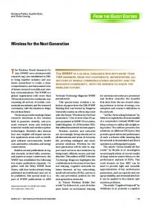
The design flows of the previous processors for SDR, such as EVP [5], SODA [8], AnySP [10], were starting from the analysis of the target algorithms described in C code. They pay little attention to the relationship of the Bit-Error-Ratio (BER) of communication system and processor architecture. In order to design a high usability processor with minimum area and power cost, we should consider BER in processor design flow. Figure 1 shows the communication domain specific processor design flow we used in this paper. Communication Domain System Model
System Level Simulation
Datatype&Operation Model
System Level Design
Processor Cycle-Accurate Model
System Level Profile
Processor Cycle-Accurate Simulation&Profile
Application Complextiy Model
Processor RTL Description
Application Analysis Optimized Processor RTL Model
System Level Processor Design
Figure 1. Design flow of processor for communication system
A. System Level Simulation In this step, we complete the system model of the target communication system, and choose MATLAB and Monte Carlo simulation to generate the relationship of BER and system implementation. As the data representation of MATLAB is IEEE-754 double float-point, while most processors for SDR, including GAEA, only support fixed-point, we should find a feasible solution to quantify float-point data to fixed-point data. In this step, we determine the data representation and memory organization of the processor designed. Our target domain is MIMO-OFDM based next generation wireless communication systems. From the comparison of the float-point model and the fixed-point model of WiMAX, we found the BER of 16-bit fixed-point data representation system can not reach as the float-point one, while 20-bit fixed-point one can. In order to meet the performance requirement and minimize the power and area, GAEA should support 20-bit fixed-point data. B. System Level Profile This step follows the system level simulation. The target model is rewritten with C language, and the fixed-point model is analyzed through simulators, such as CCS simulator, in this step. Table I shows the load and parallel feature of the WiMAX kernel algorithms. The load of the kernel algorithms occupy more than 97% of the whole computing load, while the rest algorithms just occupy less than 3%.The inter-algorithm communication mode follows typical producer and consumer
mode, and the typical inter-algorithm communication addressing modes are sequential stream mode, buffered interval interweaved mode (i.e. interweaved), word hop mode (i.e. channel estimation), and block hop mode (i.e. STBC decoding, sub-carrier map/demap). The next generation wireless communication systems use many new operations, such as reciprocal square root, matrix inversion, matrix multiply, QR decompose, and so on. TABLE I.
WIMAX KERNEL ALGORITHMS COMPUTING FEATURE
Algorithm
Load (Mops) 15251 4281 1336 243 116
Viterbi FIR FFT Chan Est. STBC
Load (%) 70.3 19.7 6.2 1.1 0.5
SIMD (Width) 64 64 256 3 384
Parallel Threads 1054 4 64 16 16
C. System Level Processor Design In this step, we complete the processor design. Instruction set, pipeline, and memory hierarchy are first designed according to the data type model, the operation model, and the complexity model generated in application analysis step. The simulator and profile dictations to record the statistics, such as utilizations of different components like register file are then implemented using C code. Based on the analysis of benchmarks running on the simulator, we optimize the architecture and get the optimized architecture. Finally, the GAEA RTL model will be implemented in Verilog HDL. GAEA ARCHITECTURE
IV.
A. GAEA Overview Figure 2 shows the system level architecture of GAEA, GAEA is mainly comprised of data processing unit MPE and control unit LEON3 [15]. There are 4 MPEs in one GAEA, and sometimes 1-2 coprocessors will be appended to process the ultra complex algorithms, such as LDPC decoding and Turbo decoding. MPEs and coprocessors share the Level 2 Memory through the 64-bit SC-TDM bus. As the controller component, LEON3 completes the task initialization and scheduling of MPEs, the SC-TDM bus and inter-MPE synchronization timing and controlling and so on. When GAEA works as a super node of MPP-NoC system, NoC interface should be appended. LEON3 SC-TDM BusController
MPE Pipeline
MPE
L1
Pipeline
MEM
L1 MEM
MPE Pipeline
L1 MEM
MPE Pipeline
L1 MEM
64-bit SC-TDM Bus
COPE
L1
Level 2 Memory
NOC-IF
MEM
Figure 2. GAEA architecture
GAEA supports three types of memory access operations. The local memory of the LEON3 core is independent for storing the LEON3 programs and the data, and the data cache
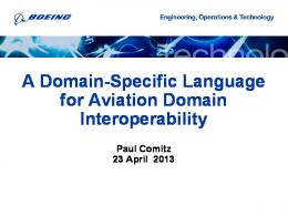
and instruction cache are all 4KB. Every MPE has its private local memory, L1MEM, MPE can only fetch instructions from instruction memory named IMEM, of which the capacity is 8KB, and can only load and store data with data memory named MBDMEM, of which the capacity is 40KB. When MPE wants to operate on the data in L2MEM, of which the capacity is 128KB, it should first load it into L1MEM by specific DMA instructions, when MPE wants to shared data with other MPEs, it should copy data into L2MEM by specific DMA instructions. The programs of MPEs are stored as data in LEON3 memory. When the GAEA processor starts, the LEON3 core first copies the MPE programs from its local memory into MPEs, as the L1MEM of MPE is also mapped to the LEON3 memory space. B. SC-TDM Bus System According to the analysis in section III, the inter-algorithm communication and kernel computing can be parallelized. When one MPE is dealing with the current data block, the memory system can copy and prepare the next data block for it. As communication systems are all hard real-time systems, memory copy and kernel computing should be done in predictable time. In order to parallelize memory copy and computing under the control of programmers, this paper proposes a novel shared memory bus, named SC-TDM bus. There are mainly two differences between SC-TDM bus and conventional bus. Firstly, the bus arbiter of SC-TDM bus is software program not hardware arbiter logic. Secondly, the arbiter cycle of SC-TDM bus is time slot, not bus cycle. Time slot is a conception from communication system, and in SCTDM bus system, a time slot is composed of several bus cycles, the number of the bus cycles contained in one time slot is determined by software, and the ID of the master device holding the time slot is also determined by software. As software program is the bus arbiter, it can get the bus utility state in design time and runtime, so programmer can know the exact time cost of memory copy operations, and can start new thread to deal with the new data block in proper time. As program can control the bus explicitly, the GAEA architecture is suitable for kinds of applications and standards with varied inter-algorithm communications. Figure 3 shows the implementation of the SC-TDM bus based on the LEON3 core. The SC-TDM bus is composed of bus logic layer, bus controller layer and bus scheduling layer. The bus logic layer is built with interconnect lines. The signals of bus arbitration are from the bus controller layer. IMEM
LEON3 Core Pipeline (bypass datapath is not showed)
Fetcher
Decoder
Regfile
Bus Scheduling Layer DMEM mem mapper APB
EXE Unit
EXC Unit
Bus Controller Layer APB-IF Time Slot Seed Array
Configure Memory
Controller FSM Arbitrator
Counter
Bus Logic Layer Bus Access Signal From PEs
Write Bus
Read Bus
Bus Access Signal From PEs
Figure 3. SC-TDM Bus based on LEON3
The bus controller layer, which is the main component of SC-TDM bus system, generates the bus arbitration signals according to the bus scheduling algorithm fed by the LEON3 core. The SC-TDM bus controller is designed as a slave device attached to the APB bus of LEON3. The APB-IF is the interface of the LEON3 core and the bus controller. Time Slot Seed Array is a runtime parameter table, which contain the time slot number of all the master devices which will be scheduled in the current scheduling period, including the “IDLE” device. When the “IDLE” device holds the bus, the bus controller can turn down the power support of the bus logic layer and the L2MEM to save power consumption. The Configure Memory, of which the capacity is 2KB, is used for storing scheduling algorithms. The Controller FSM generates the bus arbitration signals. According to figure 4, the scheduling algorithm elements include scheduling blocks and scheduling instructions. The instruction sequences are the scheduling algorithms. One scheduling block, of which the length is 2*(3+M)B, describes the behavior of one scheduling period, including the length of the scheduling period and time slot, the master device sequences and their time slot numbers. The scheduling instructions which are 16-bit length are used to organize scheduling blocks according to the target applications. There are four types scheduling instructions. Normal instructions are used to determine where to fetch scheduling blocks and times to do it, while JUMP, LOOP, and Control instructions are used to control the scheduling instruction flow. The LEON3 core is the main parts of bus scheduling layer. It writes the scheduling algorithms to the Configure Memory when watchdog timeouts or when applications need. #0 scheduling block
Period-len Time-slot-len Time-slot-num Device0 Time-slot-num Device1
...
Time-slot-num DeviceM
#N scheduling block
Period-len
… … … … … …
Normal Scheduling Instruction 0
Time-slot-len Time-slot-num Device0 Time-slot-num Device1
...
Time-slot-num DeviceM
0
BLOCKADDR(9-bit)
LOOPCNT(3-bit)
INT(2-bit)
Scheduling Jump Instruction 0
1
TARGETADDR(14-bit)
Scheduling LOOP Instruction 1 0 BLOCKCOUNT(9-bit) LOOPCNT(3-bit)
INT(2-bit)
Scheduling Control Instruction CONTROLWORD(14-bit) 1 1
Memory space 0
(N-1)*(2+M+1)
Figure 4. SC-TDM bus scheduling algorithm elements
C. MPE Architecture Figure 5 shows the architecture of MPE. According to the results showed in section III, the data representation supported in MPE includes 20-bit signed fixed-point integer (half word), 40-bit signed fixed-point integer (word), and complex number (word), of which the real part and imaginary part are all 20-bit signed fixed-point integers. The pipeline of MPE is different from other processors for SDR applications, such as EVP, and AnySP. Conventional processors exploited hybrid issue and execution of scalar instructions and SIMD vector instructions through two pipelines with separated register files and function units, resulting in the low utilization of the register files and function units. MPE uses one integrated pipeline to support 4-issue of scalar instructions and SIMD vector instructions. The width of
SIMD vector is 4-cluster for word instructions and 8-cluster or 4-cluster for half word instructions. C0_EALMU0
...
ICDEN0
...
...
...
Fetcher
S C T D M
C3_EALMU0 IMEM Controller
Instruction Memory (8KB)
B U S
C0_EALMU1
... Vector Register File (160bit*16)
...
...
C0_AGU0
...
C0_AGU1
...
...
...
...
C3_AGU0
SC-TDM BUS IF
...
C3_EALMU1
...
Issuer
ICDEN1
...
M B D M C
MBD MEM (8*5KB)
...
C3_AGU1
Figure 5. Matrix Process Engine architecture
0
0
4
1
2
2
6
3
1
4
5
5
3
6
7
(a ) C F I R
7
(b ) F F T
Figure 6. specific data exchange network modes
Inter-Cluster Data Exchange Network (ICDEN) is an optional pipeline stage. There are two ICDENs to support the operands exchange between different clusters of the two function unit sets: EALMU0 and EALMU1. Non-vector instructions or vector instructions without ICDEN flag will bypass this stage. ICDEN includes two kinds of networks. The general data exchange network, which is implemented in OMEGA network, supports SIMD shuffle of the words or half words read from the same line of the vector register file. The specific data exchange networks are designed to support the specific data exchange of operations, such as FFT, CFIR and so on. As the SIMD width of MPE is 4 when the operands are complex data, so 4-point convolution can be done in one cycle using one EALMU function unit set, and 16-tap CFIR can be done in 4 cycles as figure 6(a) shows using one EALMU function unit set. When one new sample point is fed into MPE for CFIR, the original sample sequence should shift as figure
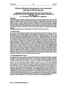
Figure 7(a) shows the implementation of AGUs. There are two load store units in every SIMD cluster. The AGUs of different SIMD cluster can work cognately or independently. When they work cognately, the addresses of cluster1~cluster3 will be calculated by adding HOPLENREG*index and the address generated by C0_AGU0, index is the related cluster index number. If they work independently, the AGUs at different clusters will calculated the target address according to the addressing modes and related registers independently. In this mode, MPE supports linear mode, base mode, bit invert mode and circular mode. C0_Ri
C0_IMM
C3_Ri
C0_BAR0
+
0
MPE Pipeline
C3_IMM
C3_BAR0
C0_BIM
bitintv
...
MBDMC 40 40 40 40 +
0 HOPLENREG
40 40 40 40
DMLD/ST DEC
C3_BIM
bitintv Crossbar0
40
Crossbar1
DMA Engine
40
*3 +
C0_AGU0
cluster0_address C0_AGU3 cluster3_address
(a) AGUs
64
All the instructions will read the 160-bit operands from the vector register file, which have 8 read ports and 4 write ports. When the instructions are the scalar instructions, only the first 40-bit will be sent to the next stage. The operations of SIMD instruction and scalar instructions are different when they are in execution stages. The scalar instructions will be executed only in the function units, of which the names have the prefix C0_, while the SIMD instructions will be executed in the entire 4-cluster function units. Take the complex multiply instructions as an example. SC.CMUL which is a scalar instruction will be executed in function unit C0_EALMU*, while VT.CMUL will be executed in the function unit set including C0_EALMU*~C3_EALMU*, notation “*” can be 0 or 1, which is determined by the logic in issue stage.
6(a), and the shift modes are supported in ICDEN. Fiure6 (b) shows the shuffle networks implemented in ICDEN to accelerate FFT. There are three types of shuffle networks related with the 3 states of 8-point FFT, with which 8-point FFT can be done in 3 cycles without storing the intermediate results. The kernel operations of N-point FFT ( ), such as the first 9 iterations butterfly operations of 1024-point FFT, can be organized into operation sequences using the shuffle networks (the twiddle factors be generated from lookup table), decreasing the executing time. To support the kernel algorithms of the next generation wireless communication systems, several specific instructions are introduced in MPEs, such as butterfly [16], Add-Compare-Select, and so on.
b 0
b 1
b 2
b 3
b 4
b 5
b 6
b 7
SC-TDM Bus
Multi-Bank Duo Port MEMory (MBDMEM)
(b) MBDMC
Figure 7. block diagram of AGUs & MBDMC
Figure 7 (b) shows the implementation of MBDMC. The main parts of MBDMC are crossbars, and DMA engine. The DMA Engine is designed to copy data between L2MEM and L1MEM (IMEM and MBDMEM). As the data representation of L2MEM is 32 bit, while the base data representation of MBDMEM is 40 bit, data rounding will be done in the DMA engine controlled by MPE pipeline through DM LD/ST instructions. The address generation mode is the main issue of DMA engine design time. DMA Engine is designed to support stream sequential, block hop and word hop mode. The AGU of DMA Engine is similar to the AGUs in figure 7(a). V.
EVALUATION AND IMPLEMENTATION
We have built the GAEA cycle-accurate simulator and the related profile tools to evaluate the performance of GAEA. Table II lists the benchmarks we implemented. All the benchmarks are the highest complexity algorithms in the next generation wireless communication systems. Each benchmark is composed of two sets of sub-benchmarks with different parameters. Benchmark FFT is designed to complete N-point Complex FFT for one time. Benchmark CFIR is designed to do the low pass filter of a 320-word complex number sequence. Benchmark VIT is designed to decode 56 words of 8-bit IQ data from convolution encoder using the viterbi algorithm.
Benchmark M-M and QR are designed to do the complex matrix multiply and complex matrix QR decomposes for 100 times and 24 times in sequence. TABLE II. Benchmark FFT CFIR VIT M-M QR
BENCHMARK DESCRIPTION
SB0 512-point 16-tap viterbi(133,171) 2X2 Matrix 2X2 Matrix
SB1 1024-point 32-tap viteribi(561,753) 4X4 Matrix 4X4 Matrix
We have implemented the benchmarks with GAEA MPE assemble language. Figure 8 shows the assemble code of 4X4 complex matrix multiply. It supposes matrix A and matrix B are stored in MBDMEM, and matrix B has been transposed by the DMA Engine. The main part of the program is the Kernel shown in figure 8. It contains 31 instructions which will be executed in 11 cycles (The instruction with postfix “|” will be issued with the previous one instruction). The Kernel loops two times, and generates all the elements of the new matrix, so it needs 23 cycles, while the additional instruction is the zerooverhead loop instruction LOOP @Kernel, 2. LOOP @Kernel , 2 Kernel : VT. LD R0, R14@A VT. LD R1, R14@A+1 | VT. LD R2, @B VT. LD R3, @B+1 | VT. LD R4, @B+2 VT. LD R5, @B+3 | VT. CMUL R0, R2, R6 VT. CMUL R0, R3, R7 | VT. CMUL R0, R4, R8 VT. CMUL R0, R5, R9 | VT. CMUL R1, R2, R10 VT. CMUL R1, R3, R11 | VT. RDADD R6, R6 | VT. RDADD R7, R7 |
VT. CMUL R1, R4, R12 VT. CMUL R1, R5, R13 | VT. RDADD R8, R8 | VT. RDADD R9, R9 | VT. RDADD R10, R10 VT. RDADD R11, R11 | SC. ST R6 R14@C | SC. ST R7 R14@C+1 | VT. RDADD R12, R12 VT. RDADD R13, R13 | SC. ST R8 R14@C+2 | SC. ST R9 R14@C+3 | SC. ST R10 R14@C+4 SC. ST R11 R14@C+5 | ADD R14, R14, 8 SC. ST R12 R14@C+6 | SC. ST R13 R14@C+7 |
Figure 8. GAEA assemble code example
The next generation wireless communication systems use some similar algorithms, only the algorithm parameters are different. One standard maybe use different parameters for different applications. In order to evaluate whether the GAEA is suitable for standard evolution and application variation, we have compared SB0 with SB1. Figure 9 shows the cycle number of SB0 and SB1 running on one GAEA MPE. The cycle number of the 1024-point FFT is 2.18 times of the 512point FFT, which is matched with the computing complexity of FFT evolution considering the CPU time for bit reverse operation. So the MPE architecture is a balanced design, no part will be the apparent bottleneck when the applications evolve. SB0
cycle number
4000
SB1
3000 2000 1000 0 FFT
CFIR
VIT
M-M
QR
Figure 9. Performance comparison of benchmarks under difference parameter
In order to find whether the multi-core architecture of GAEA is suitable for standard evolution and application
variation, we have mapped the SB1 into one MPE and on GAEA with four MPEs. Figure 10 shows the cycle number of SB1 running on one MPE and GAEA with four MPEs. The cycle number of GAEA is the cycle number of the critical path running on one of the four MPEs. In most benchmarks besides M-M and QR, it supposes all the original data are stored in L2MEM, and the results should be written back into L2MEM, so the cycles for DMA engine to move data will be included if the move process is in the critical path. When benchmark FFT was mapped into GAEA, the micro pipeline was used. The first MPE read the original data from L2MEM, completed the first 3 iterations butterfly operations of FFT, wrote the results to L2MEM, then started to process the next 1024-point FFT sequence. The rest MPEs completed the rest 7 iterations like the first MPE, except the last MPE, it did only the 10th iteration butterfly operations and wrote back the results into L2MEM. As the loads were not balanced and additional DMA engine move cycles were included, the speedup ratio of benchmark FFT is 2.6. When benchmark CFIR was mapped into GAEA, the input 320 words were divided into 4 groups. Each group had 80+31 words, the additional 31 words which were from the previous group, were used for the low pass filter of the first word in each group , as SB1 was a 32-tap CFIR. The speedup ratio of CFIR is reduced to 2.87 because of the DMA operations of the additional words. As the word sequence from the same encoder can not be divided, meanwhile multi-channel encoder or the word sequences from the different frames are all independent from each other, so when benchmark VIT was mapped into GAEA, we supposed the input words can be divided into four groups and can be decoded independently in four MPEs. When benchmark M-M and QR were mapped into GAEA, all the original data are stored in MBDMEM, as both benchmark are only the parts of the kernel algorithms like channel estimation. The speedup ratios are linear as all the matrixes are operated independently. According to the results, the cycle numbers of SB1 running on GAEA are much smaller than one MPE, therefore the multi-core architecture of GAEA also can work together to accelerate one kernel algorithms when needed. When the kernel algorithms are mapped onto the GAEA, SC-TDM bus scheduling algorithm will be used. Take FFT as an example, every MPE will read and write 1024 words, to simplify the scheduling processing, the time slot length can be set as 256, so in every time slot one MPE can read or write 1024 words. The scheduling period can be 4, and every MPE occupies one time slot in one scheduling period. The scheduling algorithm is simple, containing one scheduling block. The instruction sequence contains only two instructions, one normal instruction to read the scheduling block, and one jump instruction to jump to the normal instruction again when one scheduling block is over. As many related research processors did not open its simulator, and the benchmarks are not like the ones in table 2, we only compare MPE with commercial single core C64x DSP, as figure 11 shows. The results of C64x are from TI Website. As MPEs have more function units, and more specific instructions than C64x, the speedup ratios of MPE over C64x are significantly high.
cycle number
One
4000
GAEA is a shared memory multi-core SoC based on Software Controlled Time Division Multiplexing Bus. The kernel of GAEA is the Matrix Process Engine, which is optimized in the parallel processing scheme, the pipeline and instruction set. The evaluation results and the implementation results show that GAEA architecture is suitable for the next generation wireless communication systems.
Four
3000 2000 1000 0 FFT
CFIR
VIT
M-M
QR
Figure 10. Performance comparison of SB1 on one MPE and four MPEs
C64x
speedup
4
GAEA MPE
[1].
0 FFT
CFIR
VIT
M-M
[2].
QR
Figure 11. Speedup of one MPE over C64x
[3].
To evaluate the area and power of GAEA, we implemented it with Verilog HDL. It is synthesized with Synopsys Design Complier with TSMC 90nm cell library under 350MHz (LEON3 core is under 100MHz). The memories were generated with Artisan Memory Complier. Table 3 shows the Area and power of GAEA. The dynamic power is estimated under 350MHz (LEON3 core is under 100MHz), and the logic flip factors and the memory switch factors are all estimated according to the profile results of the benchmarks showed in this section, and the leakage power is estimated as 30%.
Component MPE pipeline MPE register file L1MEM (8+40KB) LEON3 Core (4+4KB) SC-TDM Bus L2MEM (128KB) GAEA(90nm)
This work was partly supported by the Microprocessor Innovation Team of China (IRT0416), 863 Program of China (2007AA01Z287), and National NFSC of China (06970037). REFERENCES
2
TABLE III.
ACKNOWLEDGMENT
AREA AND POWER ESTIMATED OF GAEA Units 4 4 4
Area(mm2) 2.5 0.8 6.5
Power(mW) 204 158 64
1
0.7
16
1 1
0.3 1.7
21 18
1
12.5
481
The peak computing capability of GAEA is 43.75 Gops; and MPP architecture with four GAEAs can afford 175Gops. The peak performance power ratio of GAEA is estimated as 91.0 Mops/mW. Given the performance power ratio gain from coprocessors, specific instructions, and technology scaling, GAEA can be used in the next generation wireless communication systems. VI.
CONCLUSION
The next generation wireless communication systems bring with new challenges on the architecture design of processors for SDR applications. In order to solve these problems, this paper proposed a novel processor architecture named GAEA under a novel domain specific system level design flow.
[4].
[5].
[6]. [7]. [8]. [9].
[10].
[11]. [12]. [13]. [14]. [15]. [16].
The 3rd Generation Partnership Project. “3GPP TS 36.21 V8.4.0 Technical Specification,” 2008.09 IEEE STD 802.16eTM-2005 and IEEE STD 802.16TM-2004/Cor12005, Part 16: “Air Interface for Fixed Broadband Wireless Access Systems,” IEEE Computer Society and IEEE Microwave Theory and Techniques Society, 28 February, 2006. Glossner J., Iancu D., Moudgill M., et al. “Trends in low power handset software defined radio,” Proceedings of the Embedded Computer Systems: Architectures, Modeling, and Simulation, Jul. 2007. Lee H., Lin Y., Harel Y., et al. “Software defined radio - A high performance embedded challenge,” Proceedings of the 1st International Conference on High Performance Embedded Architectures and Compilers, Nov. 2005. Svan Berkel K., Heinle F., Meuwissen P. P. E., et al, “Vector processing as an enabler for software-defined radio in handheld devices,” Eurasip Journal on Applied Signal Processing, 2005, 2005(16): 2613-25. Andre Duller, Gajinder Panesar, and et al, “Parallel Processing-the picoChip way!,” Communicating Process Architectures-2003. Schulte M., Glossner J., Jinturkar S., et al, “A low-power multithreaded processor for software defined radio,” Journal of VLSI Signal Processing, 2006, 43: 143-159. Lin Y, Lee H, Woh M, et al, “SODA: A high-performance DSP architecture for software-defined radio,” IEEE Micro, 2007, 27(1): 11423. Woh M, Lin Y, Seo S. W., et al. “From SODA to Scotch: The Evolution of a Wireless Baseband Processor,” Proceedings of the 41st Annual IEEE/ACM International Symposium on Microarchitecture, Nov. 2008. Mark Woh, Sangwon Seo, Scott A. Mahlke, and et al. “AnySP: anytime anywhere anyway signal processing,” Proceedings of the 36th IEEE/ACM International Symposium on Computer Architecture, June 2009. Torsten Limberg, Markus Winter, Marcel Bimberg, and et al, “A Fully Programmable 40 GOPS SDR Single Chip Baseband for LTE/WiMAX Terminals,” Proceedings of IEEE 2008. Anders Nilsson, Eric Tell, and et al. “Design methodology for memoryefficient multi-standard baseband processors,” Proceedings of AsiaPacific Conference on Communications 2005, Oct. 2005. H. Corporal, Microprocessor Architectures: From VLIW to TTA. Chichester, UK: John Wiley & Sons, 1997. Paul Heysters, Gerard Smit, Egbert Molenkamp, and et al. “A Flexible and Energy-Efficient Coarse-Grained Reconfigurable Architecture for Mobile Systems,” Journal of Supercomputing, 26, 283–308, 2003. Gaisler Research, “GRLIB IP Core User’s Manual V1.0.15,” April 2007. Mamidi S., Blem E., Schulte M. J., et al. “Instruction set extensions for software defined radio,” Microprocessors and Microsystems, 2009, 33(4): 260-72.