Journal of Software Engineering for Robotics
8(1), December 2017, 45-64 ISSN: 2035-3928
Domain-Specific Language Modularization Scheme Applied to a Multi-Arm Robotics Use-Case Dennis Leroy WIGAND1 Arne NORDMANN2 Niels DEHIO3 Michael MISTRY4 Sebastian WREDE1 2
1 Technical Faculty, Bielefeld University, Germany, {dwigand, swrede}@techfak.uni-bielefeld.de Corporate Sector Research and Advance Engineering, Robert Bosch GmbH, Germany,
[email protected] 3 Research Institute for Robotics and Process Control, TU Braunschweig, Germany,
[email protected] 4 School of Informatics, University of Edinburgh, Scotland,
[email protected]
Abstract—The development of robotics systems requires a coherent design, implementation, and integration of multiple domainspecific software artifacts that provide the application-specific capabilities. Model-driven software development (MDSD) provides an efficient methodology that enables the design, integration, and verification of robotics applications already at the level of multiple domain-specific models. While the application of MDSD for the engineering of robotics systems is conceptually promising, the interoperability, composability, and reusability of developed domain-specific languages and resulting models are challenging. In this article, we discuss the requirements for language modularization and composition from a robotics perspective and introduce a language composition approach for component-based robotics systems. We use a state-of-the-art language workbench, which supports reuse, extensibility, and refinement of domain-specific languages and code generators. We present and discuss a case study to evaluate the proposed extension and composition approach from a language developer’s perspective as well as from a language user’s perspective, i.e. the perspective of the roboticist supported by our set of domain-specific languages. Index Terms—Model-Driven Engineering, Domain-Specific Language, Code Generation, DSL Modularization, Generator Composition.
1
I NTRODUCTION
A
DVANCED robotics systems such as service, entertainment, or versatile industrial robots with cognitive interaction skills require the coherent design, integration, and verification of heterogeneous software artifacts from multiple domains such as motion planning and control, multi-modal perception, machine learning, or interaction design jointly realizing the application-specific requirements. Model-driven software development (MDSD) using domain-specific languages provides a promising methodology to improve the application development process [1] for such robotics systems, e.g., by facilitating separation of concerns (SoC) and separation of roles (SoR) [2], [3]. Its successful application has been shown in domains such as avionics [4] or automotive [5].
Regular paper – Manuscript received July 15, 2017; revised July 15, 2017. Digital Object Identifier: 10.6092/JOSER 2017 08 01 p45 • This work was supported by the European Communitys Horzion 2020 robotics program ICT-23-2014 under grant agreement 644727 - CogIMon and was supported by the Cluster of Excellence EXC-277: Cognitive Interaction Technology (CITEC) at Bielefeld University. • Authors retain copyright to their papers and grant JOSER unlimited rights to publish the paper electronically and in hard copy. Use of the article is permitted as long as the author(s) and the journal are properly acknowledged.
A domain-specific language (DSL) is characterized by its expressive focus towards a specific domain [6] and the definition of formal notations that are intuitively understandable for domain experts [7]. A large number of DSLs were proposed covering many of the relevant (sub-)domains in robotics [8]. Among these proposed languages, many co-exist in the literature targeting similar concerns. Both, conceptually and technically, the model-driven robotics community nowadays still lacks significant reuse of models, domain-specific languages, and tools, which leads to a huge amount of reimplementation for the same aspects and high fragmentation. In contrast to component-based software engineering [9] where principles such as modularity, extensibility, and reuse are comparably well understood [1], [10], the composability of domain-specific languages and their resulting models is still challenging [4], [10], [11], [12]. For a composition to be successful, a large number of challenges need to be considered, above all, separation of concerns [2], [13] and support for language evolution [4], [12]. In robotics software engineering, only a small body of work considers scalable composition in model-driven approaches despite the observation that for most non-trivial robotics applications it is already necessary to compose and reuse different languages and models [14], each dealing with specific concerns of the system. Reducing
c 2017 by D. L. Wigand, A. Nordmann, N. Dehio, M. Mistry, S. Wrede www.joser.org -
Journal of Software Engineering for Robotics 8(1), December 2017
46
Fig. 1: Visualization of the three composition dimensions. The computation- (CIM [15]) and platform-independent (PIM [15]) models are represented within the Capabilities dimension. Together with the two other dimensions, platform-specific models (PSM [15]) are formed. The abstraction increases from right to left.
the fragmentation as well as the overall development costs by reusing existing DSLs within and across projects [4] is essential to apply model-driven development in robotics at scale. The main contribution of this article addresses the aforementioned challenge by introducing a concept for language modularization and composition in robotics (see Fig. 1) based on a state-of-the-art language engineering approach. In Sec. 2 the main requirements for composable DSLs are outlined from a robotics perspective, while Sec. 3 briefly discusses language workbenches with dedicated support for composition. Sec. 4 introduces the scheme for language composition and generator composition, which is specifically tailored to componentbased robotics systems and supports reuse, extensibility, and refinement of domain-specific languages and code generators. Conform to the structure of Sec. 4, we present an exemplary composition in Sec. 5 that describes the necessary aspects to support the KUKA LWR 4+ [16] light-weight robotic arm using the Open Robot Control Software (Orocos) [17] with our approach. Sec. 6 presents a qualitative and a quantitative evaluation of the introduced language modularization from a language developer’s perspective, whereas Sec. 7 discusses our approach from a language user’s perspective. In Sec. 8 we present and discuss related work on language modularization and composition before Sec. 9 provides a conclusion.
2
C HALLENGES
OF
DSL M ODULARIZATION
Most papers with a focus on language modularization and composition have one particular aspect in common: they address the need to overcome various challenges during the design and development phase of modular language families. Among those, the challenges of language composition and evolution [18], [19], [20], [4], [21] stand out. As long as a (sub-)domain is not entirely covered by a DSL, language evolution is imminent. Over time, developers need to extend
a DSL to find and incorporate the correct abstractions to represent the domain properly (DSL extension [20], [21]). Even then, a completely explored domain is usually not set in stone, especially when our understanding of it changes (DSL refinement [4], [19]). The impact of each evolution can range from tiny to massive w.r.t. the languages as well as their global composition. The key question that developers are facing is how to adapt an existing language or a family of languages to changing requirements while keeping the impact as small as possible, to avoid a cascade of changes propagating through the entire composition [4]. Different authors take on the various challenges and rephrase them into guidelines for DSL design and modular arrangement. Only guidelines that can or should be applied to DSL composition are considered in the following. These guidelines are numbered consecutive in form of (GX). Dhouib et al. [11] promote the specification of componentbased robotic architectures (G1) as most robotics systems are component-based. They urge to reuse language modules for composition (G2). Thus, achieving modularity by creating highly modular language fragments is mandatory for composition and distributed development [22]. However, languages should not only be composed together, but extended and reused by other DSLs as well. Collecting DSL modules in a library-based approach offers the possibility to import only the required language and generator modules for a task [10]. The need to support exchangeability of heterogeneous modules (G3), while maintaining a target-platform independent core, is addressed by [11], [22]. This kind of composition can only be achieved through composable language fragments that use well defined interfaces (G4), allowing the exchange of realizations and restricting language evolution to defined extension points [10]. By demanding the support of smooth evolution of DSLs (G5) through agile and reusable code generation, as well as through extensible DSL realizations, the challenge of language evolution is addressed by [11] too. Thus, DSLs should be able to incorporate superficial changes without the need to create an entirely new realization. Eventually, Karsai et al. [22] state that all guidelines, instead of being followed blindly, should be considered by the language designer and applied where suitable.
3
TOOL S UPPORT
Tools called Language Workbenches support the developer to overcome some of the aforementioned challenges, by facilitating language development and making modularization and composition technically feasible. These aspects are especially well supported in projectional tools, whereas parser-based tools offer only limited support. Parser-based tools, such as ANTLR1 and Eclipse xText2 , cannot guarantee that two or more language extensions work together without conflicts, 1. http://www.antlr.org/ 2. http://www.eclipse.org/Xtext/
D. L. WIGAND et al./ Domain-Specific Language Modularization Scheme Applied to a Multi-Arm Robotics Use-Case
because the resulting grammar might be ambiguous. On the other hand, projectional tools, such as Intentional [23] and the JetBrains Meta Programming System (MPS)3 , avoid disambiguity by eliminating the need for parsing [7]. Furthermore, MPS was designed particularly to work with sets of integrated languages. According to Voelter [12], it supports four different kinds of composition: Referencing, Extension, Reuse and Embedding. Out of those four, embedding is most interesting for our approach, since it combines two previously unrelated languages [24] without modifying either of the languages. This renders embedding a non-invasive kind of composition and makes the languages maintain their modularity. MPS provides a mechanism called annotation that can be categorized into the class of embedding. Although the annotation mechanism does not introduce any kind of dependency, it does perform syntactic composition. Annotations can be attached to arbitrary elements of the abstract syntax and can be shown together with the concrete syntax of the respective elements. To achieve syntactic composition, annotations take advantage of the projectional view provided by MPS, in which the concrete syntax is directly projected from the abstract syntax. Details on the features of MPS and its support for modularization can be found in [12], [24].
4
L ANGUAGE C OMPOSITION
FOR
R OBOTICS
To benefit from composition mechanisms in the context of robotics, these mechanisms need to be integrated into meaningful parts of a framework that consider the specifics of the robotics domain. Hence, we propose a language composition and generation approach for component-based robotics systems that supports extensibility and refinement (see Sec. 2). It is realized using JetBrains MPS to draw on the provided benefits (see Sec. 3). We separate domain-specific language modules along three orthogonal dimensions (see Fig. 1). This was inspired by the work of Ratiu et al. [24], who used two modularization dimensions to enable easy and modular implementation of DSLs and analyses, which can then be reused between different DSLs. Under consideration of the Robot Application Development Process (RAP) introduced in [1], we chose the following three dimensions as the foundation to cover the different aspects of robotic systems: • Hardware Platform, representing robotic platforms including their kinematic structure and robot-specific constraints resp. interfaces. • Software Platform, describing the characteristics of software frameworks (i.e. middlewares) and their requirements for code generation. • Capability, defining isolated aspects that are reusable and can be composed to cover the functional concerns of the system. 3. http://jetbrains.com/mps
47
Fig. 2: Visualization of the interfaces used to compose the Capability, Software Platform, and Hardware Platform dimension.
By using the annotation mechanism introduced in Sec. 3, flexible composition of the dimensions is possible. This way, dimension-overarching models can be created, representing various robotics systems. Such a system can encompass a set of capabilities, adapted to a set of software frameworks, deployed on different robots in the real world as well as in simulation. 4.1
Core Dimensions
To ensure exchangeability and modularity, as well as distributed development, it is essential that all languages and generators are realized to be as independent and self-contained as possible. The three previously mentioned dimensions are introduced in the following. Each of those dimensions, contains a language module that acts as the common base for all other languages in the same dimension. The common bases equip derived languages with the necessary mechanisms (see Fig. 2) to support the embedding4 of other modules. Annotations are a particular kind of embedding mechanism that provides an extension point for enriching models with additional information. 4.1.1 Hardware Platform Dimension In this dimension, the different hardware platform aspects are modeled, including kinematics, dynamics, safety constraints, control interface, etc. Explicitly considering the hardware platform has proven to be an essential concern for robotic systems, since it is addressed by various contributions, e.g., [25], [26], [27], [28]. To represent robotic platforms, we introduced the Hardware Platform DSL, which forms the common base in this dimension. It provides the IAmHardwarePlatform annotation as an anchor point to force robot-specific constraints onto models based on the Capability dimension (see Fig. 2). This may be necessary since the computational capacity can vary significantly between different robots. Thus, for instance, the number of active components could be restricted to fit the robot’s limits. Each supported hardware platform is represented as a language module that extends the base language 4. Type of composition introduced by Voelter [12] and described in Sec. 3.
Journal of Software Engineering for Robotics 8(1), December 2017
48
Fig. 3: Illustration of an exemplary set of capabilities. Language modules (displayed in the UML package syntax) that are important in the course of this work are displayed with their main concepts. Each colored area represents a (sub-)domain of robotics systems [8]. While the pure description of concepts for e.g., a robotic platform is considered a capability, the actual concretization (including constraints) for a particular robot (e.g., KUKA LWR 4+) falls into the associated platform dimension.
and which specializes the inherited annotation to match its platform (see IAmLWR4+ in Fig. 2). Considering the Nao5 robot as an example [29]: No language modules for hardwarespecific requirements need to be added, since NAOqi6 is specifically tailored to the robot, implicitly containing Nao hardware constraints. However, for a different robot, such as the KUKA LWR, it is necessary to add robot-specific constraints. Apart from robotics platforms, this dimension also covers the modeling of other hardware, such as sensors (e.g. force-torque sensors), interfaces (e.g. ethernet ports), as well as computation units (e.g. external workstations). 4.1.2 Software Platform Dimension In contrast to the hardware platforms, this dimension mainly focuses on component frameworks (e.g., Orocos, ROS [30] and CCA [31]), middlewares (e.g., YARP [32], RSB [33]), as well as all other software-related aspects, such as interface protocols (e.g., the Fast Research Interface Library (FRI)7 ). The majority of the represented software frameworks in this dimension is eventually targeting code generation. The common base language in this dimension is the Software Platform DSL. Analogous to the Hardware 5. https://www.ald.softbankrobotics.com/en/cool-robots/nao 6. http://doc.aldebaran.com/2-1/naoqi/index.html 7. http://cs.stanford.edu/people/tkr/fri/html/
Platform dimension, it entails the IAmSoftwarePlatform annotation, which can also be attached to models based on languages from the Capability dimension. Each software platform is represented by adapting the inherited annotation from its base language to the respective platform (see IAmOrocos in Fig. 2). Further, modules in this dimension can be specially tailored towards extending or restricting capabilities to software requirements. These modules extend associated capabilities and introduce platform-specific constraints or generators. Through the mechanisms inherited by the Software Platform DSL, its automatic application is restricted to model fragments based on the particular capability and which are annotated with the associated software platform. For instance, to use a capability that generates motions for NAOqi as software framework, a constraint needs to be introduced on the motion part of the model. This constraint would then ensure that the background motion behavior of the NAOqi API is disabled, which otherwise overrides motion commands when active. In case a software platform requires additional information that would in the future be provided by a model aspect that is not available yet, the platform can make use of the demand mechanism. This mechanism is provided by the common base language of this dimension. By specializing and implementing the IDemand interface, a demand can be
D. L. WIGAND et al./ Domain-Specific Language Modularization Scheme Applied to a Multi-Arm Robotics Use-Case
49
introduced that mandates to be fulfilled. If there is no capability that is able to comply with such a demand, the specific software platform can provide a model element that allows to manually specify the missing information, until a suitable capability becomes available. 4.1.3 Capability Dimension This dimension builds the third pillar of our approach, covering the functional parts of a system that are independent of any software and hardware framework. Each DSL in this dimension represents a capability of the robotics system that can be traced back to the Capability DSL, which forms the common base. From this language, each of the derived DSLs inherits an interface (ICanBePlatformAnnotated) that enables the embedding of language modules from the platform dimensions. This allows platform-specific constraints to be applied onto capabilities, and capabilities to be transformed by generators according to platform-specific needs. However, no direct dependencies are introduced between capability and platform language modules. Fig. 3 shows an exemplary set of capabilities categorized into different (sub-)domains. For most of the (sub-)domains there is already related work present in form of domain concepts. These could be integrated as capabilities and used together with the proposed composition approach. For further information on the chosen (sub-)domains and existing related work refer to [8]. 4.2 Extensible Language Modules Apart from the base languages, we have realized the following modules: In the Hardware Platform dimension the RobotPlatform DSL represents robotic platforms using an URDF8 /SRDF9 -based meta-model, which is provided by the Kinematics DSL. The Capability dimension incorporates the Component DSL and Coordination DSL, focusing on the structure and coordination of the components to form the abstract representation of a system. The rationale behind these languages is to cover the static view (component structure) as well as the dynamic view (system-level and task-level coordination) of a robotic system. The Component DSL is based on the Component-Port-Connector (CPC) meta-model, since most robotic systems can conceptually be boiled down to a variant of it [11], [34]. To combine the static and dynamic view, the Systems Coordination DSL was created. For instance, it allows to manipulate system components from within a state machine. Apart from the general system description, further concerns need to be covered, e.g., motion generation. To support the modeling of motion control architectures the Motion Primitive DSL, introduced in [35], was reused in our composition approach. One of its main concepts is the Adaptive Component, resembling a kinematic controller using different dynamic motion primitive types. 8. Unified Robot Description Format (URDF) http://wiki.ros.org/urdf 9. Semantic Robot Description Format (SRDF) http://wiki.ros.org/srdf
Fig. 4: Adaption the of multi-staged transformations concepts, introduced in [7], to the proposed generator composition: The intermediate layer (IL) during generation is formed by the Coordination and Component DSL. Above the two languages more specific capabilities and platform specializations of capabilities are located. They all reuse the backend generation of the intermediate layer. Below however, multiple transformations are performed from the intermediate layer into different languages, reusing the transformations from above.
4.3
Modular Generators
One of Dhouib et al.’s [11] guidelines discussed in Sec. 2 demands flexible and reusable code generation. According to Voelter et al. [7], multi-staged transformation is a common consequence of language extension. Languages are incrementally stacked on top of others, reusing the transformations of the lower languages instead of generating directly down to the lowest level (General Purpose Language (GPL) level). Thus, we composed the model transformations to support backend as well as frontend reuse with respect to the intermediate layer (IL). As visualized in Fig. 4, multiple DSLs that generate into a language of the IL (gray boxes) can reuse the intermediate language’s generators (backend-reuse). However, languages below the IL are implicitly reusing all transformations that happen above that layer. Thus, they only need to provide a transformation from the intermediate language to their own DSL to cover the generation of models from multiple languages above the IL (frontend-reuse). There are three ways for a language module to contribute to the generation in our approach. Those are used mostly by languages from the platform dimensions (software and hardware), depending on their requirements and realization: 1) If a derived language modifies the meta-model of the inherited language, while staying withing the scope of its inherited generator, it is not necessary to add additional or extend inherited generators. In this context, the scope of a generator is defined by the input pattern of the generator’s transformation. 2) However, if the modifications of the derived language go beyond the boundaries of the inherited generator’s scope, the resulting model might not be a valid input for the inherited generators anymore. Hence, the derived
Journal of Software Engineering for Robotics 8(1), December 2017
50
language needs to add or extend its (inherited) generators. 3) To provide mandatory information for generators located at a lower position in the generation pipeline, languages from the platform dimensions can use their annotation mechanism to propagate platform-related information down the pipeline. This approach has the benefit of being able to reuse the transformations of the existing languages instead of creating a separate branch in the generation pipeline for that particular case. Capability language modules do not have platform-related generators, because they are platform-agnostic. Nevertheless, platform unspecific artifacts, e.g., PlantUML10 , should be generated from these capabilities as well [29]. Hence, we introduced modules to our composition that solely contain generators. These generator-only modules transform models between completely independent languages, without introducing any additional dependencies. By packaging generators in their own modules, they can be applied in a very flexible manner only where they are needed. To ensure that generators get applied to valid models only, a generator’s input needs to meet defined constraints. Even though platform-specific generators are able to transform specific concepts of capabilities, these concepts are not considered as valid input if they are not annotated with the particular interface from the associated platform-specialization for the generator.
5
L ANGUAGE C OMPOSITION E XAMPLE
In this example, the existing language composition is extended by motion generation for the KUKA LWR 4+ platform. The application model using robot and software specific extensions is generated into executable code after applying a series of model-to-model (M2M) and model-to-text (M2T) transformations. The generation target for the functional aspects is CoSiMA11 , an Orocos-based execution framework. The initial situation for this example entails all languages introduced in Sec. 4 and the LWR 4+ robot already modeled w.r.t. its kinematics as well as its robot control interface (i.e. FRI), using the RobotPlatform DSL. 5.1
Core Dimensions
In order to add support for controlling the KUKA LWR 4+ platform, the corresponding software and hardware needs to be represented. In our case, this means extending the base languages of the platform dimensions to specialize the interfaces according to Fig. 2 for Orocos as well as for the KUKA LWR 4+ hardware. In the Software Platform dimension, the language module Orocos is created to contain the IAmOrocos annotation, which specializes IAmSoftwarePlatform (see Fig. 5). To support the KUKA LWR 4+ robot, the LWR 4+ Platform is created in the Hardware Platform 10. http://plantuml.com/ 11. http://cogimon.github.io/
Fig. 5: Illustration of the concepts supporting Orocos as a software platform in the composition. While the concepts of the Orocos DSL (blue border) specialize the necessary concepts of the Software Platform DSL (gray border), the interface ICanBePlatformAnnotated from the Capability DSL (orange border) represents the annotation target for software platforms.
dimension, specializing the IAmHardwarePlatform annotation to IAmLWR4+. Both parts lay the foundation for embedding the KUKA LWR 4+ platform and Orocos into our approach and enable the composition with existing capabilities. 5.2
Extensible Language Modules
Once the annotation mechanisms are properly adapted to support the new platforms, (language resp. generator) modules can be created in the Software Platform dimension that, e.g., enrich capabilities with Orocos specific constraints and model transformations. In this case, the Component, Systems Coordination, and Motion Primitives are specialized to Orocos Component, Orocos Systems Coordination, and Orocos Motion Primitives. In the Hardware Platform dimension, the language module LWR4+ Platform needs to be created. It contains specific constraints regarding the control modes provided by the KUKA LWR 4+ through FRI. For the sake of readability and considering that the presented use case in Sec. 7.1 focuses on controlling the KUKA LWR 4+ by generating code towards the Orocos framework, only the highly relevant language modules will be introduced more detailed in the following: 5.2.1 LWR4+ Platform With regards to the algorithmic research that will be done on the KUKA LWR4+ using Orocos, commanding the robot in joint torque mode is essential. However, in contrast to other robots that support joint torque control out of the box, the FRI interface that is offered by KUKA to remote control the robot, supports only joint position and joint impedance control as joint-space control modes. Fortunately, there is a way to achieve joint torque control on the KUKA LWR4+ by using the joint impedance mode in a special configuration. The only throwback that comes with this solution is that
D. L. WIGAND et al./ Domain-Specific Language Modularization Scheme Applied to a Multi-Arm Robotics Use-Case
51
Fig. 6: Simplified meta-model of the Component DSL (gray border) enriched by additional concepts of the Orocos Component DSL (green border) that are mandatory to create models that use Orocos as software platform. The relationship of the DSLs to the software platform specialization for Orocos, namely, the Orocos DSL (blue border) and the interface of the Capabilities DSL (orange border) shows the composability according to Fig. 2.
the robot compensates for gravity on its own. Keeping this in mind, a constraint is needed that makes sure that in the torque command, which gets send to the robot, the gravity is neglected so as if the command would be executed in a zero-gravity environment. In situations where a component sends joint torques to a robot control interface that uses the LWR 4+ Platform and FRI as the remote control interface, the constraint gets automatically triggered. As a result, the user is asked to take care of the gravity before sending the command to the robot. This constraint intertwines the Software Platform dimension (i.e. FRI), the Hardware Platform dimension (i.e. KUKA LWR 4+) and the Capability dimension (i.e. Component and Robot Component). 5.2.2
Orocos Component
The purpose of specializing the Component DSL mainly is to cover additional structural aspects that are key concepts of Orocos: For instance, so called activities12 need to be defined to manage the order and scheduling of Orocos RTT (C++) components. Since the Component DSL does not have any concept that is even remotely related to such an activity (see the gray bordered concepts in Fig. 6), it needs to be included as a new concept, i.e. RTTActivity. Hence, aspects such as 12. http://www.orocos.org/stable/documentation/rtt/v2.x/doc-xml/ orocos-components-manual.html#corelib-activities
activities are treated as mandatory for the specific software platform and, thus are reflected by a demand, in this case by the IAmOrocosDemand, which utilizes the demand mechanism from the Software Platform DSL. In contrast to optional aspects of a software platform, these demands represent aspects that need to be specified by each ComponentInst that is annotated with the Orocos platform. Furthermore, connections in the Orocos framework require a connection policy to be valid. Again, the concept of such a connection policy is not included in the Component DSL, therefore an RTTConnection extending the general connection is created that holds an RTTConnPolicy. If two Orocos components are connected, the Connection is converted into an RTTConnection, which then provides the possibility to specify a connection policy. Additionally, RTTConnections are only allowed to connect components that are annotated with the Orocos platform. 5.2.3 Orocos Systems Coordination In contrast to the Orocos Component DSL (see Sec. 5.2.2), no structural aspects are added here. Instead, the Orocos Systems Coordination DSL focuses on additional constraints and validations. Due to the Systems Coordination’s ability to interact between the structural and dynamic view, it is used to orchestrate the configuration and launch sequence of an Orocos system. This requires no additional structural changes, since for this purpose Orocos components can be treated as
Journal of Software Engineering for Robotics 8(1), December 2017
52
general components. However, configuring an Orocos component needs to be done according to its life cycle (a set of states and transitions): First, a constraint is created ensuring that all the required operations of the life cycle are exposed by the components. Second, the control flow of the configuration model is analyzed to validate the call order of these operations w.r.t. the life cycle. 5.2.4 Orocos Program Script For the structural model of an Orocos system we target the generation of Orocos Program Scripts13 (OPS), which are used to specify the components, activities, and connections of a system along with their configurations. In terms of MPS, this language acts as a so called base language to model these kinds of scripts and providing model-to-text transformations, which produce plain text artifacts according to the OPS format. 5.2.5 Orocos RTT (C++) Generating the C++ implementation of an Orocos component for instance for a motion primitive, requires the ability to produce Orocos-specific source code (cf. NaoqiModules in case of NAOqi). For this purpose, the Orocos RTT (C++) DSL provides an abstraction that allows to create models of Orocos components, which conform to the C++ base language. Through this layer between the Component and the C++ DSL, validations and constraints can be used to ensure that the input model for actual C++ source code generation is not only conforming to the C++ standard, but also that it is valid according to Orocos’ specification for C++ components. 5.3
Modular Generators
To generate artifacts such as C++ and OPS code, a suitable set of generators needs to be imported and enriched with additional Orocos generators. Following the scheme of Fig. 1, implicit generation pipelines are arranged by composing a set of generator modules. An example of the generation steps for different targets can be seen in Fig. 7. Apart from the already existing generators covering the capabilities of the system, new transformations need to be added that allow platform specific generation for Orocos. To create an Orocos RTT (C++) component implementation containing a motion primitive, a generator for Orocos motion primitives is necessary. It transforms a motion primitive concept that contains a Dynamical System [35] into a Component representation, which subsequently allows to reuse generic generators for Components, such as for system diagrams. In Fig. 7, a Component wraps a component structure around a placeholder for framework-specific content, in this case, a representation of the Dynamical System in the C++ base language. The Component is further annotated with the Orocos platform and is afterwards transformed into an abstract representation of 13. http://www.orocos.org/stable/documentation/rtt/v2.x/doc-xml/ orocos-components-manual.html#program-syntax
Fig. 7: The overall structure shown in Fig. 4 is adapted in this figure to elucidate the different generator steps along exemplary models related to the scenario in Sec. 5. To generate the artifacts at the bottom, the associated transformations are executed in a top-down manner. On the right, an Adaptive Component annotated with the Orocos platform is transformed via a Component and an Orocos RTT Component to its final C++ representation, which is plain text eventually. A Component that contains a State Machine is processed by two different generator pipelines, while maintaining an intact reference between the models and artifacts.
an Orocos C++ component implementation (i.e. OrocosRTT Component) by an Orocos Component generator. Since the motion primitive is now fully represented conforming to the targeted software framework, the annotation is not required anymore and thus removed. This is marked by the empty green circles in Fig. 7. From here on, the Orocos RTT (C++) DSL with its included Orocos-specific generators will take care of the generation into an entirely C++-based representation, which then reuses the M2T transformations provided by the C++ base language to create the C++ source for an actual Orocos RTT component. Apart from C++-based artifacts, an Orocos Program Script is generated by incorporating different heterogeneous model pieces to eventually form a complete artifact. For this purpose, there are mainly two generator modules. Each of them covers a
D. L. WIGAND et al./ Domain-Specific Language Modularization Scheme Applied to a Multi-Arm Robotics Use-Case
53
different aspect: The first generator is provided by the Orocos Component language module and takes the structural view of the system model (i.e. components, connections, etc.) as input to transform it into OPS statements. Additionally, it draws on the information provided by the Orocos-annotations to configure necessary aspects, such as the priority or frequency of the annotated component. The second generator is provided by the Orocos Systems Coordination and transforms component configurations into OPS statements. Finally, the resulting artifact incorporates the static view, configuration and launch sequence of the system in form of an OPS file, which can then be passed into the Orocos deployer14 binary to execute the system. However, to generate an Orocos component that is capable of interpreting and executing a finite-state machine (FSM) on its own, a Component from the Component DSL is created (annotated with Orocos) that holds a State Machine, which is represented in the Systems Coordination DSL with Orocosspecific extensions. Those extensions are provided by the Orocos Systems Coordination DSL. As seen in Fig. 7, the generation splits into two different pipelines: One for the state machine generation (left column) and the other one for the state machine interpreter component (2nd left column). Although the generation is separated, an intact reference between the Component and its associated State Machine is maintained. Furthermore, the Orocos Systems Coordination DSL needs to contain a generator that takes care of the generation of Orocos-specific parts in a State Machine. Reusing the Coordination DSL as IL, a generator needs to be used that transforms Orocos-annotated State Machines into a Orocos Program Script-based FSM representation. At the same time, additional artifacts can be generated from reused generator modules, such as PlantML diagrams, which can be formed for every generic system of components specified using the Component DSL.
6.1.1 Specification of comp.-based robotic arch’s. (G1) Since we based our Component DSL on the CPC metamodel, it is also inherited by every specialization of the Component DSL, such as the Motion Primitives DSL. This way, our system description is based on a well-established specification model for component-based architectures.
6
6.1.5 Support of smooth evolution of DSLs (G5) The ability to change elements of a DSL without triggering a cascade of changes, which has an impact on diverse other language modules, depends on the stability [36] of the DSLs where the change is going to happen. The stability of the modules in our approach is analyzed in Sec. 6.2.2. Since stable languages mostly have a number of languages depending on them, the probability of having a higher impact on these depending DSLs increases. Through the modular design and SoC in our approach, we minimize the dependencies between the modules. Additionally, change is mainly happening to instable modules, which do not have many dependencies. This makes sense considering the Component DSL and higherlevel languages (e.g., the Motion Primitives DSL). While the first one is based on a well-established scheme (CPC) and thus not very likely to change drastically, the latter is more prone
E VALUATION : L ANGUAGE D ESIGNER
The evaluation of the presented approach from the language designer perspective is performed qualitatively and quantitatively. First, the composition is analyzed qualitatively with regards to the guidelines introduced in Sec. 2. Afterwards, this is followed by a quantitative evaluation of the amount of reuse in our approach and the application of common objectoriented software metrics to analyze the composition. 6.1
Qualitative Evaluation
The proposed approach is discussed along the guidelines (GX) condensed in Sec. 2: 14. http://www.orocos.org/stable/documentation/ocl/v2.x/doc-xml/ orocos-deployment.html
6.1.2 Reuse language modules for composition (G2) As described in Sec. 4, the proposed composition is divided along three dimensions, separating the main concerns of robotics systems. Each dimension encompasses language or generator fragments for different aspects of that dimension. Since supporting new capabilities and platforms follows a specific scheme (see Sec. 5), reusing a significant amount of the existing implementations (e.g., language and generator fragments) becomes feasible. The fact that only a desired set of capabilities needs to be covered to support a new software platform offers the benefit of incremental and distributed development. In general, our modularization provides a library-based approach for language and generator modules, which can be loaded or unloaded at will, supporting dynamical configurations of compositions and independent evolution of languages and generators. Using such a library-based modularization is also encouraged by Horst et al. [10]. 6.1.3 Support exchanging heterogeneous modules (G3) The functional level of our proposed approach is entirely software- and hardware platform agnostic. By using the introduced composition mechanisms, the provided capabilities, e.g., components, can be generated into heterogeneous software and executed on associated hardware platforms. 6.1.4 Use well defined interfaces (G4) For the interaction between the three dimensions, we introduced interfaces (see Fig. 2) that allow non-invasive composition, using the Embedding mechanism described in Sec. 3.
Journal of Software Engineering for Robotics 8(1), December 2017
54
to language evolution. This is due to the fact that these higherlevel specializations cover different subdomains that might not be represented or accessed entirely (see Sec. 6.2.2).
6.2
Quantitative Evaluation
This part of the evaluation aims at quantifying the reuse and stability of the proposed structure for language composition. First, the actually reused elements are analyzed and compared with the additional effort that would occur through not reusing parts of existing modules. The analysis is followed by an evaluation of a stability metric [36] applied to our proposed modules. 6.2.1
Kinematics Software Platform Capabilities Component Coordination Hardware Platform Sys. Coord. Orocos Comp. Orocos Sys. Coord. NAOqi Comp. NAOqi Sys. Coord.
Reuse and Effort Analysis
To gain insights on the reuse factor of our proposal, the language modules relevant for the static and dynamic view of a system are considered. This includes the Orocos-related languages, namely Orocos Component and Orocos Systems Coordination; as well as the languages for NAOqi, introduced in [29]: NAOqi Component and NAOqi Systems Coordination. Taking a closer look at these languages in Tab. 1, it can be seen that each of these languages would contain a very high amount of additional elements in case of no reuse. Especially the Orocos Systems Coordination would need to incorporate 22.57 times more elements than it would need reusing existing languages modules. These numbers were gained by adding the language elements from the reused languages to the elements of the derived language per MPS’ aspect. Here, we assume that all elements from the reused languages are important for the derived language. Apart from several other downsides that come with monolithic and nondynamic software designs, the additional effort spent to create these language modules strongly encourages modularization similar to our approach.
Structure Editor Constraints Behavior Typesystem Intentions Dataflow Total (+%)
NAOqi Comp 73 (+59 %) 50 (+43 %) 10 (+43 %) 22 (+47 %) 28 (+65 %) 5 (+67 %) 0 (+0 %) 188 (+46 %)
Orocos Comp 42 (+282 %) 27 (+286 %) 5 (+400 %) 11 (+450 %) 13 (+333 %) 3 (+200 %) 0 (+0 %) 101 (+279 %)
NAOqi Sys.Coord 48 (+2300 %) 41 (+1950 %) 16 (+1500 %) 33 (+3200 %) 13 (+550 %) 5 (+400 %) 12 (+200 %) 168 (1443 %)
Orocos Sys.Coord 47 (+4700 %) 39 (+3900 %) 15 (+1500 %) 32 (+3200 %) 14 (+1300 %) 4 (+400 %) 8 (+800 %) 167 (2257 %)
TABLE 1: Presentation of the language development effort. The platform-specific extensions, i.e. NAOqi/Orocos Component and NAOqi/Orocos Systems Coordination, are considered as stand-alone languages without any kind of reuse. While the number in each cell indicates the number of language elements per MPS’ aspect, the percentage displays the ratio between the elements w.r.t. reuse. Compared to the NAOqi Systems Coordination that reuses other languages, the standalone version needs in total 1443 % = b 14.43 times, and for the Orocos it is even 2257 % = b 22.57 times more elements.
Ca 2 17 8 34 11 3 6 0 0 0 0
Ce 0 0 0 1 1 2 17 10 10 18 12
I 0.00 0.00 0.00 0.03 0.08 0.40 0.74 1.00 1.00 1.00 1.00
TABLE 2: Stability analysis of the modules from the proposed composition according to [36]. Ca is the afferent couplings. Ce stands for the efferent couplings. I is based on Ca and Ce, representing the instability of a module. The metric ranges from 0 (stable) to 1 (instable).
6.2.2 Stability Analysis It is essential for a composition to be founded on a stable basis of languages (see Sec. 2). Since building upon an instable base, prone to change and fluctuation, could cause cascades of changes to propagate through the entire composition. Thus, our proposed language modules are evaluated by applying a stability metric, introduced by Martin [36]. He proposes two characteristics to classify a module: Independence and Responsibility. Independent modules do not depend on anything else. Responsible modules are heavily depended upon by other modules. Modules that are both independent and responsible, do not need and should not change. Applying this metric to the concepts of language modules, the findings are displayed in Tab. 2. The metric ranges from 0 (stable) to 1 (instable). The base languages that lay the foundation to model a component-based robotic system in our proposal are close to being stable, e.g., Component, Coordination, whereas specific capabilities and their platform associations are, in this case, highly instable according to this metric. However, not all parts need or even should be stable. If all parts of a system would be entirely stable, there would be no room left for changes [36], thus preventing evolution. Nevertheless, it is obligatory to build upon a stable basis while keeping the most specific parts of the composition exposable to change. This prevents changes from rippling through the system while being able to adapt and extend the current state of composition.
7
E VALUATION : L ANGUAGE U SER
The introduced language modularization and composition was initially motivated in Sec. 2 from a language designer’s perspective, which was evaluated in the previous Sec. 6. The following section continues this discussion from a language user’s perspective, i.e. from the perspective of the roboticist and system builder15 . The qualitative evaluation in this section focuses on modeling features that help the user to handle the complex interplay 15. The semantics of the role is informed by [37].
D. L. WIGAND et al./ Domain-Specific Language Modularization Scheme Applied to a Multi-Arm Robotics Use-Case
between software, hardware, and the desired capabilities for their application. Regarding the evaluation, we decided against considering a toy example and chose one of the main scenarios of our current research project16 instead. Putting our approach in practice not only provides a suitable degree of complexity, but more importantly, facilitates the development of a highly relevant part of our research. In the following, we introduce a robotics application, which we consider a valuable use case for the presented composition approach to show where and why it excels. The chosen scenario for this use case unifies different aspects of robotics systems, such as static system description, coordination, software execution environment, hardware environment (i.e. kinematics and dynamics), as well as timing. Our approach integrates these domains in a way that they can be seen and designed independently most of the time. Therefore, distributed development and usage is enabled. In the real world, however, these aspects are not entirely decoupled, but often heavily intertwined. With the presented language composition approach, these relationships can be exploited in form of assumptions and information that are inferred across domains. Thus, we expect that support by the introduced language family is especially valuable in scenarios where there is a tight coupling between capabilities, hardware, and software. Robotics experiments with a strong focus on a single aspect of robotics, e.g., control or perception, may also be covered by our language family. [8]. Furthermore, modeling such a scenario is not only based on the composition of diverse language modules, but ultimately also on the composition of generator modules. Through our approach, this complex DSL ecosystem is able to scale with the requirements of the scenario, as long as the necessary domains are represented and available based on the three dimension presented in Sec. 4. 7.1
Multi-Arm Object Manipulation Use Case
Many tasks in daily human household activities deal with contact and are either related to wiping surfaces [38] or grasping objects [39]. Both activities require complex contact constraints. Robot motion in contact situations is constrained and typical free space motion control techniques cannot be applied directly. In modern robotics, a key challenge is to exploit or deal with these contact constraints. For this scenario, we chose a method for multi-arm manipulation of rigid objects, subject to external disturbance. 7.1.1
Scenario Description
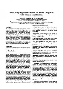
Considering a robotics system consisting of four fixed-base manipulators operating in a cooperative manner to manipulate a rigid object via a force-closed grasp (see Fig. 8). Each end-effector (i.e. triangular plate with three rubber feet) is in contact with the object and may generate arbitrary wrenches 16. Cognitive Interaction in Motion – CogIMon (see https://cogimon.eu/)
55
(a) Simulated robot setup.
(b) Real robot hardware.
Fig. 8: Presentation of the quad-arm object manipulation scenario on a simulated robot setup (a) as well as on the real robot hardware (b).
upon the object. Due to the tight contact, this system can be seen as a closed kinematic chain. The manipulators are constrained: the relative transformation between end-effectors stays constant (assuming no slipping along contact surfaces). In this scenario, for manipulation of the object, one has to consider two main objectives: First, end-effectors have to apply (internal) forces to compensate for object dynamics. Second, we want to control the object pose while end-effectors have to adapt their position and orientation to maintain the contactconstraint. Projected inverse dynamics control (PIDC) [40], [41] is an elegant framework for this purpose. This approach separates robot control into two orthogonal subspaces for contact consistent motion generation and applying contact forces. The projection is based on a Jacobian which specifies the contact con-
56
straint, assuming zero Cartesian velocities and accelerations at the contact points. PIDC ensures that constraint force does not produce any virtual work for any virtual displacement. For this, the robot is constrained such that only internal forces are allowed to enforce the contacts. Furthermore, motion generation is not allowed to effect contact constraints. The PIDC approach was validated by Ortenzi et al. [42] with a torque-controlled robot for wiping a board. PIDC can be employed for various scenarios by choosing a constrained Jacobian. When grasping an object with two (or more) end-effectors, one can employ the well studied graspmatrix constraint [43], [44]. It represents the mapping between the object twist to the twists of the contact points. Employing this constraint in a force-closed grasp situation, PIDC allows to perform motion and force tasks separately, resulting in different and independent control laws for applying desired contact forces and tracking motion tasks [45]. 7.2 Modeling Process In this section we discuss the necessary steps to model the scenario considering the separation of the different involved roles (SoR [2]). Using MPS as tool for language developers as well as language users, the scenario was completely modeled based on the language modules introduced in Sec. 5. Exploiting the projectional editing feature of MPS, we created a custom graphical editor to define the static view of a system (see Fig. 9). Together with suitable concrete syntaxes (e.g., textual, graphical) for the other aspects, an intuitive way of designing a component-based robotics system is provided. Being able to distribute and separate the development by roles at language usage level is one of the main advantages of the presented language composition approach. This not only improves efficiency and productivity, but also minimizes distractions and the feeling of being overwhelmed by an entire project. Hence, the user in a particular role is able to solely focus on the part that requires his or hers expertise. The following sections are structured according to the modeling process, which considers SoR following [2], [37]. 7.2.1 Functional Design The first task to model such a scenario is to assess its functional and non-functional requirements. By analyzing the algorithmic theory (e.g., the control scheme), the domain expert was able to identify the functional building blocks that form the control algorithm for this scenario: End-Effector Motion Controller (1) The end-effector motion controller computes torques to follow a desired trajectory (consisting of position and orientation) with the object’s center. End-Effector Force Controller (2) In contrast to the motion controller, this component enforces contact by controlling (internal) force. Projection Combiner (3) The output of both motion and force controllers is combined by projecting onto orthogonal subspaces.
Journal of Software Engineering for Robotics 8(1), December 2017
Constrained Auxiliaries (4) Variables that are necessary for PIDC, such as the projection matrix, its derivative and the constrained inertia, are computed by this functional block. Kinematics and Dynamics (5) Based on the current joint angles, the end-effector positions and velocities, end-effector Jacobians, joint space inertia matrix as well as a vector for compensating gravity and centrifugal/Coriolis are calculated and provided for further calculations. Constraint (6) By evaluating the current end-effector positions, the associated grasp matrix constraint is computed. This is used to dictate the direction of contact forces. Trajectory Generator (7) This functional block provides the desired trajectory (positions and orientations) for the object’s center. Object Pose Tracking (8) Tracks the manipulated object’s pose using an external vision system to acquire ground truth information. Contact Force Estimator (9) Estimates the contact forces. Even though the obtained signal is not precise enough for robot control, the estimated data can be used for offline evaluation or fault detection. Consequently, this block can be executed with low priority compared to other functional blocks. Together with the domain expert, the system architect then defines the system. A static view is used to describe the components and the connectivity of the system. A dynamic view is used to define the configuration and the launch sequence. For this scenario, compliant robotic manipulators need to be used that can be operated in joint torque control mode and the main control loop needs to run at 1 kHz in order to have stable control. 7.2.2 Capability Modeling Based on the insights gained from the domain expert and the system architect, the functional blocks required (but not yet available) for the desired robotics system need to be modeled by the component supplier through concepts of the Component DSL (see Fig. 10). For our scenario, the new components were added to the component repository (CCL17 ) model. CCL contains different components, the system builder can draw on to create a static system model (see Fig. 9). Using the static view, the behavior developer is able to specify the model for the dynamic view, leveraging the Systems Coordination DSL. This model includes the component configurations as well as their launch sequence (see Fig. 12). In the special case of considering the configuration of the components involved in the control scheme, the domain expert’s knowledge is required to fine-tune the behavior. Eventually, both models are used to let the robotic system execute a desired behavior. 7.2.3 Technology Mapping One of the requirements identified in Sec. 7.2.1 was a main loop update rate of 1 kHz. To fulfill this requirement Orocos 17. name of the model displayed in Fig. 9
D. L. WIGAND et al./ Domain-Specific Language Modularization Scheme Applied to a Multi-Arm Robotics Use-Case
57
Fig. 9: Screenshot of our graphical editor in MPS, displaying the modeled static view of the quad-arm object manipulation scenario. On the left, the used models are displayed, including the component- (CCL), robotic platform- (RobotRepo) and data type- (RSTRT) repository. All components, connections, etc. that form the system are displayed on the right. The purple connections highlight the main data flow for this scenario, while the numbers on the components refer to the functional blocks in Sec. 7.1. For instance, the end-effector motion controller (1) was decomposed into three components. Components without a number, represent mandatory and optional parts of the system. The components on the right include the four robot interfaces, which are necessary, but not described as functional parts of the control scheme. Additionally, logging and safety components are optional w.r.t. to the control scheme, but highly important for the safe execution.
RTT was selected as a suitable technology mapping for this scenario. Since at that point there are not yet any platformspecific aspects included in the previously created models (see Sec. 7.2.2), the software engineer maps a software platform (i.e. Orocos) to the system, or rather to each component that needs to run in an Orocos real-time environment. Since Orocos demands to have the timing of the components specified, the performance designer needs to take care of handling the different activities and the timing of the individual components in the system. Fig. 13 shows the annotated component of the task-space position controller for the end-effectors, which is associated to an activity that sets the update frequency, priority, and scheduler accordingly. To leverage Xenomai18 support, the scheduler needs to be set to ORO_SCHED_RT.
18. https://xenomai.org/
7.2.4
Hardware Mapping
To deploy the modeled system for the LWR 4+, the respective hardware platform needs to be available to be used by the components that interface with the robot. Hence, the robot engineer needs to provide the kinematics as well as dynamics model (see Fig. 11). However, if the desired robot is already available in the so called robotic platform repository (RobotRepo17 ) model, the robot engineer can also draw on the existing robots and load the respective models from the repository. The next step is to configure one robot component per controlled robot. In order to control the entire robot, or a subset of the available kinematics, so called kinematic chains need to be defined. Such a chain, consists of a sequence of joints that are connected via links. Depending on the scenario, the desired chains are defined and thus available to be controlled in the intersection of control modes supported by the involved joints. In our model, a robot component is
58
Journal of Software Engineering for Robotics 8(1), December 2017
Fig. 10: Illustration of the component description model for the JointPositionController available in the CCL repository. controllable once it contains a fully defined kinematic chain. For this, a chain requires a set of consecutive joints as well as one of the available control modes to indicate the active mode. Only one control mode can be active per chain at a time. In this case, the entire kinematic chain of the KUKA LWR 4+ is used and set into a special kind of joint torque mode (+ gravity compensation), since the robot along with its FRI interface does not provide direct joint torque control.
Fig. 11: Kinematics and dynamics model of the KUKA LWR 4+, including meta information, i.e. collision meshes for simulation and collision detection.
7.3 Refining the Models The modeling process presented in the previous section (see Sec. 7.2) represents one iteration cycle. In the first itera-
Fig. 12: Behavior model for the system in form of a state machine. To access the callable operations on a component, the model draws on the available components in the static view (see Fig. 9) and their associated component descriptions (see Fig. 10).
tion the process needs to be followed in a rather strict order, since the technology and hardware mapping phase can only be entered after a platform-independent model is created. The next iterations are targeted at refining the models and resolving issues or triggered constraints. Thus, the order is less strict. Already during the first iteration (as soon as two intertwined aspects are used) the users can benefit from the composition approach, which allows to make assumptions across models and across (sub-)domains, supporting the user while developing the system (see the example presented in Sec. 7.3.2). Once the first iteration is finished, aspects from every dimension are incorporated in the models. Although, benefits are created for the users by treating these aspects resp. language modules as independent during the development phase, some parts are highly coupled from a functional point of view. Exploiting this kind of intertwinedness is where our composition approach excels the most. Examples for user support w.r.t. possible refinements in further iterations are presented in the following:
D. L. WIGAND et al./ Domain-Specific Language Modularization Scheme Applied to a Multi-Arm Robotics Use-Case
Fig. 13: Visualization of the end-effectors’ task-space position controller component, annotated with the Orocos platform and associated with an activity to define the timing. For this activity, an update frequency of 0.001[s] = b 1[kHz], a priority of 15, and as scheduler ORO_SCHED_RT is chosen, which enforces the Xenomai support for execution (if available).
7.3.1
Adapting the Architecture to Other Platforms
For instance, depending on the hardware platform, the generic control architecture is automatically scaled towards the robot platform. Of course, there are limits: A control architecture for manipulators cannot be ported to a humanoid robot without further knowledge. This, however, does work among different manipulators that expose the mandatory control modes. Using the inferred e.g., degrees of freedom (DoF) from the robot platform provides the required information to warn the user, when manually specifying a value that does not match the DoF of the controlled robot (see Fig. 14).
Fig. 14: Illustration of a warning that occurs when the degrees of freedom of a controller component are manually overridden, although they were already inferred automatically from the robotic hardware platform that should be controlled.
This kind of intertwined yet non-invasive composition of modules allows further to efficiently adapt specific parts to changing requirements. For instance, deploying a modeled system on another software or hardware platform does not require the involvement of the Function Developer nor the Component Supplier. Only the expert for the specific platform is required to make the proper changes. The general system will adapt accordingly (within realistic bounds). However, deploying a controller that does not make sense (on a semantic level) for a particular robot, will most likely result in an unwanted behavior.
59
Fig. 15: Presentation of the textual representation for a system containing two components: A controller that sends joint torque commands to a robot component that interfaces to a KUKA LWR 4+. The entire kinematic chain of the robot is set to a non-standard joint torque control mode with additional semantics (+gravity), indicating that gravity will be compensated for by the robot. This triggers a constraint and informs the user about possible semantic inconsistencies. 7.3.2 Coping with Peculiarities of Special Compositions The composition can yield even more complex assumptions when all three dimensions, i.e. the Software Platform dimension, the Hardware Platform dimension, and the Capability dimension, are considered together. As discussed in Sec. 5.2.1, a constraint is triggered when a component sends joint torques to a robot control interface that uses the LWR 4+ Platform and FRI as the remote control interface. After triggering the constraint, the user is asked to take care of removing the gravity from the torque command before sending it to the robot, since the LWR 4+ already compensates for gravity on its own (see Fig. 15). However, our control components offer a functionality to be called by the constraint to automatically neglect the gravity in the computations. 7.3.3 Modeling Currently Unsupported (Sub-)Domains Another advantage of the presented approach is the fact that a system can directly be modeled in the generic Component DSL, System Coordination DSL, etc, even though there might not be a (sub-)domain-specific language module for a particular aspect available yet. This is especially useful when considering research projects, where it is often the case that not all parts required for a research prototype are supported by language modules right from the start. For instance, we were able to model a prototype of the scenario at a point in time where the (sub-)domain of motion primitives was not yet covered by the composition. The prototype however, was then used as an additional asset to the domain analysis, which resulted in a language module for motion primitives, i.e. the Motion Primitives DSL. With that new module, the model was incrementally refined to include the motion primitives aspect. The same principle can be applied to e.g., a software platform. Before the timing aspects of Orocos were modeled, the different activities needed to be parameterized manually via the behavior model. Afterwards, using the modeled activities, the configuration is automatically generated.
Journal of Software Engineering for Robotics 8(1), December 2017
60
Fig. 16: Depiction of the generation process w.r.t. the used models and resulting artifacts. The root models are arranged in the upper half of the figure, while the generated artifacts (i.e. OPS script and C++ implementations) are displayed in the lower half. The models that act as input for the generation process are connected with the double-lined arrows towards the artifact they contribute to.
7.4
Resulting Models and Generated Artifacts
The outcome of the modeling process for this scenario is expressed by the following models (see Fig. 16): • a model repository containing the kinematic and dynamic description of the robotics platforms (RobotRepo). • a model repository for all available components (CCL). • a model defining the static view of the system, which embeds – a model part for the mapping the Orocos as the software platform. – a model part for the configuration (e.g., control modes and kinematic chains) of the KUKA LWR 4+ as the hardware platform. • a model representing the configuration and launch sequence of the system. After transforming these models through the pipeline of composed generators for this particular composition, two types of artifacts are created: An OPS script that executes the described behavior of the robotic system as well as different Orocosspecific C++ implementations for the components. The fact that the different heterogeneous model elements created from different roles are compiled to a homogeneous artifact through the composed compilers is a great simplification from a user’s perspective and eases execution of the potentially complex model.
8
R ELATED W ORK
There is an increasing number of DSLs in the context of robotics systems, covering a variety of different concerns [8].
However, in most cases, these DSLs are self-contained without being considered as parts of a composition at all. Lesire et al. [46] propose a design process based on the Mauve DSL, separating the concerns of computation and configuration. The DSL can be traced back to CPC including behavioral aspects. It provides modeling and validation of component-based systems with particular focus on the nonfunctional requirements of real-time. Even though we share the same belief of applying CBSE and SoC to facilitate development, their approach diverges from ours. Since they consider the computation concern as “black box” and do not model it, they are not able to generate computational code. In our approach, we model and generate the computational code (e.g., in the Motion Primitives DSL), instead of just mapping the components to their platform-dependent implementation. For compatibility with already existing computational code, however, we also support such a kind of mapping. Apart from that, their approach is not very robotics-specific since it does not consider the robotics platform, which is an essential part of a robotics system. Instead, they solely focus on the software platform, i.e. the (Orocos) middleware. The RobotML DSL to design, simulate, and deploy robotics applications is presented by Dhouib et al. [11]. RobotML sets the focus on modeling platform-independent robotics applications that can be deployed on multiple target platforms. It is realized as an UML profile. Similar to the Mauve DSL, the system’s architecture, communication, and behavioral aspects can be modeled and components are mapped to platformspecific “black box” implementations. Although this approach separates the robotics system description from the platform description and explicitly represent the execution environment, the approach does not distinguish between software and hardware platforms. However, we believe that it is obligatory to consider software and hardware as two individual concerns since a system using a particular middleware might be deployed on different hardware platforms that each demand the consideration of different requirements. As far as we can tell, RobotML is a single DSL, not utilizing the concept of language modularization, thus preventing distributed development. Furthermore, it uses direct M2T transformations to generate towards a target-platform. However, according to Voelter et al. [7], multi-staged M2M transformations increase understandability, maintainability and offer to benefit from reusing existing transformations. While utilizing solely direct M2T transformations may be suitable for some purposes, our approach conforms with the statements of Voelter et al. especially when considering extensibility and composition (see Sec. 4). The 3-View Component Meta-Model (V3 CMM) [5] provides a platform-independent modeling approach for component-based application design. It allows the modeling of a system with modular high-level components including their behavioral aspects. Furthermore, it supports M2M and M2T transformations towards different generation targets. Al-
D. L. WIGAND et al./ Domain-Specific Language Modularization Scheme Applied to a Multi-Arm Robotics Use-Case
though it offers a fully model-driven approach for software deployment, it is not particularly robotics-specific. In contrast to that, our proposed approach represents robotics-specific aspects due to the explicit consideration and modeling of the robot platform. Hochgeschwender et al. [47] propose a model-based approach for software deployment in robotics. They state that the deployment of a robotics system needs to be separated from the core functionalities. Similar to our approach, they decompose a robotics application into software and hardware aspects. However, their approach supports a far more finegrained and extensive model of robot platforms compared to ours. While we currently only support the kinematic structure and actuators implicitly as joints, they are able to define the entire robot model in terms of sensors and actuators. In order to build a robotics application, they draw on a set of features and necessary transformations to target generation against a framework (i.e. deployment files for Orocos). These features are similar to the concerns covered by languages in the Capability dimension of our approach. Unfortunately, in their work they do not describe their generator composition nor the interaction of platform-independent and -dependent parts in detail. With the MontiArcAutomation architecture modeling framework, Ringert et al. [48] present an approach for language and code generator composition of CPC systems. Based on their language workbench MontiCore, they apply their approach to robotics applications. Although they share our mindset w.r.t. almost all presented challenges of composition, e.g., support of heterogeneous target platforms (see Sec. 6.1.3), they do not consider the robot (hardware) platform explicitly. Furthermore, the approach only allows covering concerns based on component behavior modeling languages. As far as we can tell, the approach does not support adding arbitrary concerns to the composition. Regarding the aspect of modeling the static view of a system, the BRICS component model (BCM) [34] and the BRIDE toolchain [49] are interesting approaches to tackle the issue. While the idea of BCM is to provide guidelines (e.g., in form of the CPC meta-model) and tools to structure the development process of components and component-based systems in a framework- or application-agnostic way, BRIDE provides an Eclipse-based modeling environment to specify framework-independent systems (incl. component interfaces) and to generate implementation skeletons for chosen target languages (i.e. ROS and Orocos). Both approaches follow the model-driven engineering approach and Separation of Concerns. Our proposed approach is strongly influenced by BCM and BRIDE. For instance, we are leveraging an extended version of the CPC meta-model from BCM as mentioned in Sec. 4.2 and we also conform to the Separation of Concerns mindset. However, while BCM and BRIDE cover only the static view of a system, our proposed approach unifies many more aspects and is able to cover all robotics (sub-)domains
61
eventually. Regarding the generation of Orocos component interfaces and specifying the deployment and configuration of such components, multiple solutions exist. Apart from some already mentioned publications, the Robot Construction Kit (Rock) [50] offers a slightly different approach. After specifying the component interface and its dependencies in a concrete syntax, the resulting file can be processed by their oroGen transpiler to produce an Orocos-based C++ component skeleton implementation. Eventually, the developer is then able to implement the behavioral aspects into the skeleton. This is similar to the BCM and BRIDE approach, except for the fact that, as far as we can see, oroGen only provides onedirectional generation. Furthermore, Rock allows to describe the deployment and configuration of components using Ruby scripts. Since there is no tight integration of both aspects, no extensive assumptions or constraints can be made over the different aspects. This is a disadvantage, since this kind of intertwinedness (e.g., between the static and dynamic view of a system) is where our approach benefits the most from.
9
C ONCLUSION
In this article, we discussed the need for language and generator composition as well as the accompanying challenges. We introduced a three-dimensional model-based composition approach for developing component-based robotics systems, which addresses the main challenges of composition while being specifically designed to conceptually cover heterogeneous concerns of the robotics domain, e.g., coordination, motion, and perception. Apart from modeling platform-independent capabilities, we specifically consider software and hardware platform modeling as separate dimensions. Together with a truly modular and flexible multi-staged code generator composition to support multiple heterogeneous generation targets, these three dimensions form the pillars of our approach. We evaluated the extensibility and general structure of our composition in a case study, where we successfully covered the concern of motion generation for the KUKA LWR 4+ platform using our Orocos-based framework CoSiMA. The language composition fosters separation of roles while still supporting language users in coping with the complex interplay of the different system aspects, e.g., hardware, software, and capabilities. Motivated by the insights gained from the discussion of related work in the direction of general language composition and MDE approaches in robotics, we encourage awareness for the need of language modularization and composition especially for domain-specific modeling of advanced robotic systems. Future work on the basis of this article may include an extension to the component-based systems architecture in terms of (sub-)system composition, since this is expected to further increase reuse. In addition to that, we are currently investigating the interplay between the three presented dimensions, to identify further (domain-specific) relationships that
Journal of Software Engineering for Robotics 8(1), December 2017
62
can be made explicit to contribute to an enhanced modeling support. Ultimately, a user evaluation is intended, which will provide the required insights that help to refine the presented approach.
R EFERENCES [1]
[2]
[3]
[4]
[5]
[6]
[7]
[8]
[9]
[10]
[11]
[12]
[13]
R. Bischoff, T. Guhl, E. Prassler, W. Nowak, G. Kraetzschmar, H. Bruyninckx, P. Soetens, M. Haegele, A. Pott, P. Breedveld, J. Broenink, D. Brugali, and N. Tomatis, “Brics - best practice in robotics,” in Proc. 41st Int. Symp. Robotics and 6th German Conf. Robotics, Jun 2010, pp. 1–8. [Online]. Available: http: //ieeexplore.ieee.org/document/5756905 1, 4 C. Schlegel, A. Lotz, and A. Steck, Robotic software systems: From code-driven to model-driven software development. INTECH Open Access Publisher, 2012. [Online]. Available: http://ieeexplore.ieee.org/ document/5174736/ 1, 7.2 C. Schlegel, A. Lotz, M. Lutz, D. Stampfer, J. F. Ingl´es-Romero, and C. Vicente-Chicote, “Model-driven software systems engineering in robotics: covering the complete life-cycle of a robot,” it-Information Technology, vol. 57, no. 2, pp. 85–98, 2015. [Online]. Available: https://doi.org/10.1515/itit-2014-1069 1 J. White, J. H. Hill, J. Gray, S. Tambe, A. S. Gokhale, and D. C. Schmidt, “Improving domain-specific language reuse with software product line techniques,” IEEE software, vol. 26, no. 4, pp. 47–53, 2009. [Online]. Available: http://ieeexplore.ieee.org/document/5076458/ 1, 2 D. Alonso, C. Vicente-Chicote, F. Ortiz, J. Pastor, and B. Alvarez, “V3cmm: A 3-view component meta-model for model-driven robotic software development,” Journal of Software Engineering for Robotics, vol. 1, no. 1, pp. 3–17, 2010. [Online]. Available: https://joser.unibg.it/ index.php?journal=joser&page=article&op=view&path%5B%5D=18 1, 8 A. van Deursen, P. Klint, and J. Visser, “Domain-Specific Languages: An Annotated Bibliography,” ACM Sigplan Notices, 2000. [Online]. Available: http://dl.acm.org/citation.cfm?id=352035 1 M. V¨olter, S. Benz, C. Dietrich, B. Engelmann, M. Helander, L. Kats, E. Visser, and G. Wachsmuth, DSL Engineering – Designing, Implementing and Using Domain-Specific Languages. CreateSpace Independent Publishing Platform, 2013. [Online]. Available: http: //voelter.de/dslbook/markusvoelter-dslengineering-1.0.pdf 1, 3, 4, 4.3, 8 A. Nordmann, N. Hochgeschwender, D. Wigand, and S. Wrede, “A Survey on Domain-Specific Modeling and Languages in Robotics,” Journal of Software Engineering in Robotics, 2016. [Online]. Available: https://joser.unibg.it/index.php?journal=joser&page=article& op=view&path%5B%5D=100 1, 3, 4.1.3, 7, 8 D. Brugali and P. Scandurra, “Component-Based Robotic Engineering (Part I),” Robotics and Automation Magazine, no. 12, 2009. [Online]. Available: http://ieeexplore.ieee.org/document/5306930/ 1 A. Horst and B. Rumpe, “Towards Compositional Domain Specific Languages,” 7th Workshop Multi-Paradigm Modeling, pp. 1–5, 2013. [Online]. Available: http://www.se-rwth.de/publications/Towards Compositional Domain Specific Languages.pdf 1, 2, 6.1.2 S. Dhouib, S. Kchir, S. Stinckwich, T. Ziadi, and M. Ziane, “Robotml, a domain-specific language to design, simulate and deploy robotic applications,” in Proc. 3rd Int. Conf. Simulation, Modeling, and Programming for Autonomous Robots, ser. SIMPAR’12. Berlin, Heidelberg: Springer-Verlag, 2012, pp. 149–160. [Online]. Available: https://link.springer.com/chapter/10.1007/978-3-642-34327-8 16 1, 2, 4.2, 4.3, 8 M. Voelter, Language and IDE Modularization and Composition with MPS. Braga, Portugal: Springer Berlin Heidelberg, 2011, pp. 383–430. [Online]. Available: https://link.springer.com/chapter/10. 1007%2F978-3-642-35992-7 11 1, 3, 4 D. Groenewegen and E. Visser, “Declarative access control for webdsl: Combining language integration and separation of concerns,” in Proc. Int. Conf. Web Engineering. Yorktown Heights, New York, USA: IEEE, July 2008. [Online]. Available: http://ieeexplore.ieee.org/ document/4577881/ 1
[14] A. Nordmann, N. Hochgeschwender, and S. Wrede, “A survey on domain-specific languages in robotics,” in Proceedings of the 4th International Conference on Simulation, Modeling, and Programming for Autonomous Robots - Volume 8810, ser. SIMPAR 2014. New York, NY, USA: Springer-Verlag New York, Inc., 2014, pp. 195–206. [Online]. Available: http://dx.doi.org/10.1007/978-3-319-11900-7 17 1 [15] OMG. (2014, Jun) Model Driven Architecture (MDA) Guide. [Online]. Available: http://www.omg.org/cgi-bin/doc?ormsc/14-06-01.pdf 1 [16] R. Bischoff, J. Kurth, G. Schreiber, R. Koeppe, A. Albu-Sch¨affer, D. Beyer, O. Eiberger, S. Haddadin, A. Stemmer, G. Grunwald, and K. R. Gmbh, “The KUKA-DLR Lightweight Robot arm a new reference platform for robotics research and manufacturing Summary / Abstract Stages of research and product development,” Joint 41th Internatiional Symposium on Robotics and 6th German Conference on Robotics, pp. 741–748, 2010. [Online]. Available: http://www.vde-verlag.de/proceedings-en/453273110.html 1 [17] H. Bruyninckx, P. Soetens, and B. Koninckx, “The real-time motion control core of the Orocos project,” in IEEE International Conference on Robotics and Automation, 2003, pp. 2766–2771. [Online]. Available: http://ieeexplore.ieee.org/document/1242011/ 1 [18] W. Cazzola and D. Poletti, “Dsl evolution through composition,” in Proceedings of the 7th Workshop on Reflection, AOP and Meta-Data for Software Evolution, ser. RAM-SE ’10. New York, NY, USA: ACM, 2010, pp. 6:1–6:6. [Online]. Available: http: //doi.acm.org/10.1145/1890683.1890689 2 [19] S. Erdweg, P. G. Giarrusso, and T. Rendel, “Language composition untangled,” in Proceedings of the Twelfth Workshop on Language Descriptions, Tools, and Applications, ser. LDTA ’12. New York, NY, USA: ACM, 2012, pp. 7:1–7:8. [Online]. Available: http: //doi.acm.org/10.1145/2427048.2427055 2 [20] L. Renggli, M. Denker, and O. Nierstrasz, “Language boxes: Bending the host language with modular language changes,” in Proceedings of the Second International Conference on Software Language Engineering, ser. SLE’09. Berlin, Heidelberg: Springer-Verlag, 2010, pp. 274–293. [Online]. Available: https://doi.org/10.1007/978-3-642-12107-4 20 2 [21] S. Erdweg, T. van der Storm, M. V¨olter, L. Tratt, R. Bosman, W. R. Cook, A. Gerritsen, A. Hulshout, S. Kelly, A. Loh, G. Konat, P. J. Molina, M. Palatnik, R. Pohjonen, E. Schindler, K. Schindler, R. Solmi, V. Vergu, E. Visser, K. van der Vlist, G. Wachsmuth, and J. van der Woning, “Evaluating and comparing language workbenches,” Comput. Lang. Syst. Struct., vol. 44, no. PA, pp. 24–47, Dec 2015. [Online]. Available: http://dx.doi.org/10.1016/j.cl.2015.08.007 2 [22] G. Karsai, H. Krahn, C. Pinkernell, B. Rumpe, M. Schneider, and S. Vlkel, “Design guidelines for domain specific languages,” in Proc. 9th OOPSLA Workshop Domain-Specific Modeling, 2009, pp. 7–13. [Online]. Available: https://arxiv.org/abs/1409.2378 2 [23] C. Simonyi, M. Christerson, and S. Clifford, “Intentional software,” in Proc. 21st Annu. ACM SIGPLAN Conf. Object-oriented Programming Systems, Languages, and Applications, ser. OOPSLA ’06. New York, NY, USA: ACM, 2006, pp. 451–464. [Online]. Available: http://doi.acm.org/10.1145/1167473.1167511 3 [24] D. Ratiu, M. Voelter, Z. Molotnikov, and B. Schaetz, “Implementing modular domain specific languages and analyses,” in Proc. Workshop Model-Driven Engineering, Verification and Validation. ACM, 2012, pp. 35–40. [Online]. Available: http://mbeddr.com/files/modevva2012. pdf 3, 4 [25] M. Frigerio, J. Buchli, and D. Caldwell, “A Domain Specific Language for Kinematic Models and Fast Implementations of Robot Dynamics Algorithms,” in Proc. Workshop Domain-Specific Languages and models for Robotic systems, 2013. [Online]. Available: https://arxiv.org/abs/1301.7190 4.1.1 [26] A. K. Ramadorai, U. Ganapathy, and F. Guida, “A generic kinematics software package,” in Proc. Int. Conf. Robotics and Automation. IEEE, 1994, pp. 3331–3336. [Online]. Available: http://ieeexplore.ieee.org/document/351058/ 4.1.1 [27] M. Bordignon, K. Stoy, and U. P. Schultz, “Generalized programming of modular robots through kinematic configurations,” in Proc. Int. Conf. Intelligent Robots and Systems. IEEE, 2011, pp. 3659–3666. [Online]. Available: http://ieeexplore.ieee.org/document/6094811/ 4.1.1 [28] M. Frigerio, J. Buchli, and D. G. Caldwell, “Model based code generation for kinematics and dynamics computations in robot
D. L. WIGAND et al./ Domain-Specific Language Modularization Scheme Applied to a Multi-Arm Robotics Use-Case
[29]
[30]
[31]
[32]
[33]
[34]
[35]
[36] [37]
[38]
[39]
[40]
[41]
[42]
[43]
[44]
controllers,” in Proc. Workshop Software Development and Integration in Robotics, 2012. [Online]. Available: https://www.iit.it/it/people/ marco-frigerio?docId=76&format=raw&view=download 4.1.1 D. L. Wigand, A. Nordmann, M. Goerlich, and S. Wrede, “Modularization of domain-specific languages for extensible componentbased robotic systems,” in 2017 First IEEE International Conference on Robotic Computing (IRC), April 2017, pp. 164–171. [Online]. Available: http://ieeexplore.ieee.org/document/7926534/ 4.1.1, 4.3, 6.2.1 M. Quigley, K. Conley, B. P. Gerkey, J. Faust, T. Foote, J. Leibs, R. Wheeler, and A. Y. Ng, “Ros: an open-source robot operating system,” in ICRA Workshop on Open Source Software, 2009. [Online]. Available: http://www.willowgarage.com/ papers/ros-open-source-robot-operating-system 4.1.2 A. Nordmann, M. Rolf, and S. Wrede, Software Abstractions for Simulation and Control of a Continuum Robot. Berlin, Heidelberg: Springer Berlin Heidelberg, 2012, pp. 113–124. [Online]. Available: https://doi.org/10.1007/978-3-642-34327-8 13 4.1.2 G. Metta, P. Fitzpatrick, and L. Natale, “Yarp: Yet another robot platform,” International Journal of Advanced Robotic Systems, vol. 3, no. 1, p. 8, 2006. [Online]. Available: http://dx.doi.org/10.5772/5761 4.1.2 J. Wienke and S. Wrede, “A middleware for collaborative research in experimental robotics,” in 2011 IEEE/SICE International Symposium on System Integration (SII), Dec 2011, pp. 1183–1190. [Online]. Available: http://ieeexplore.ieee.org/document/6147617/ 4.1.2 D. Brugali and L. Gherardi, “Hyperflex: A model driven toolchain for designing and configuring software control systems for autonomous robots,” Studies in Computational Intelligence, vol. 625, pp. 509–534, 2016. [Online]. Available: https://www.scopus.com/inward/record.uri? eid=2-s2.0-84958559705&doi=10.1007%2f978-3-319-26054-9 20& partnerID=40&md5=d18f20fdc514a4a2868e251d6b070124 4.2, 8 A. Nordmann, S. Wrede, and J. Steil, “Modeling of movement control architectures based on motion primitives using domain-specific languages,” in Proc. Int. Conf. Robotics and Automation, May 2015, pp. 5032–5039. [Online]. Available: http://ieeexplore.ieee.org/abstract/ document/7139899/ 4.2, 5.3 R. Martin, “Oo design quality metrics: an analysis of dependencies,” ROAD, vol. 2, no. 3, 1995. 6.1.5, 6.2, 2, 6.2.2 Robotics and Embedded Systems, Technische Universit¨at M¨unchen. (2017, May) Roles in the Ecosystem [RobMoSys Wiki]. [Online]. Available: http://robmosys.eu/wiki/general principles:ecosystem:roles 15, 7.2 D. Leidner, A. Dietrich, M. Beetz, and A. Albu-Sch¨affer, “Knowledgeenabled parameterization of whole-body control strategies for compliant service robots,” Autonomous Robots, vol. 40, no. 3, pp. 519– 536, 2016. [Online]. Available: https://link.springer.com/article/10. 1007/s10514-015-9523-3 7.1 A. M. . Okamura, N. Smaby, and M. R. Cutkosky, “An overview of dexterous manipulation,” in IEEE/RSJ Int. Conf. on Robotics and Automation, vol. 1, 2000, pp. 255–262. [Online]. Available: http://ieeexplore.ieee.org/document/844067/ 7.1 F. Aghili, “A unified approach for inverse and direct dynamics of constrained multibody systems based on linear projection operator: Applications to control and simulation,” IEEE Transactions on Robotics, vol. 21, no. 5, pp. 834–849, 2005. [Online]. Available: http://ieeexplore.ieee.org/document/1512343/ 7.1.1 M. Mistry and L. Righetti, “Operational space control of constrained and underactuated systems,” in Proceedings of Robotics: Science and Systems VII. MIT Press, 2011. [Online]. Available: http://www. disneyresearch.com/wp-content/uploads/mistry rss11 final.pdf 7.1.1 V. Ortenzi, M. Adjigble, J. A. Kuo, R. Stolkin, and M. Mistry, “An experimental study of robot control during environmental contacts based on projected operational space dynamics,” in IEEE/RAS Int. Conf. on Humanoid Robots, 2014, pp. 407–412. [Online]. Available: http://ieeexplore.ieee.org/document/7041392/ 7.1.1 S. Erhart and S. Hirche, “Internal force analysis and load distribution for cooperative multi-robot manipulation,” IEEE Transactions on Robotics, vol. 31, no. 5, pp. 1238–1243, 2015. [Online]. Available: http://ieeexplore.ieee.org/document/7206596/ 7.1.1 F. Caccavale, P. Chiacchio, A. Marino, and L. Villani, “Six-dof impedance control of dual-arm cooperative manipulators,” IEEE
[45]
[46]
[47]
[48]
[49]
[50]
63
Transactions on Mechatronics, vol. 13, no. 5, pp. 576–586, 2008. [Online]. Available: http://ieeexplore.ieee.org/document/4639601/ 7.1.1 H.-C. Lin, J. Smith, K. Kouhkiloui Babarahmati, N. Dehio, and M. Mistry, “A projected inverse dynamics approach for dual-arm cartesian impedance control,” arxiv, Under review. [Online]. Available: https://arxiv.org/abs/1707.00484 7.1.1 C. Lesire, D. Doose, and H. Cass´e, “Mauve: a component-based modeling framework for real-time analysis of robotic applications,” in Proc. 7th Workshop Software Development and Integration in Robotics, 2012. [Online]. Available: https://hal-onera.archives-ouvertes. fr/hal-01060327 8 N. Hochgeschwender, L. Gherardi, A. Shakhirmardanov, G. K. Kraetzschmar, D. Brugali, and H. Bruyninckx, “A model-based approach to software deployment in robotics,” in Proc. Int. Conf. Intelligent Robots and Systems, 2013, pp. 3907–3914. [Online]. Available: http://ieeexplore.ieee.org/document/6696915/ 8 J. O. Ringert, A. Roth, B. Rumpe, and A. Wortmann, “Language and code generator composition for model-driven engineering of robotics component & connector systems,” Journal of Software Engineering for Robotics, vol. 6, no. 1, pp. 33–57, 2016. [Online]. Available: https://joser.unibg.it/index.php?journal=joser&page=article& op=view&path%5B%5D=87 8 A. Bubeck, F. Weisshardt, and A. Verl, “Bride - a toolchain for framework-independent development of industrial service robot applications,” in ISR/Robotik 2014; 41st International Symposium on Robotics, June 2014, pp. 1–6. [Online]. Available: http://ieeexplore. ieee.org/document/6840120/ 8 S. Joyeux and J. Albiez, “Robot development: from components to systems,” in 6th National Conference on Control Architectures of Robots. Grenoble, France: INRIA Grenoble Rhˆone-Alpes, May 2011, p. 15 p. [Online]. Available: https://hal.inria.fr/inria-00599679 8
Dennis Leroy Wigand received his M. Sc. degree in computer science from Bielefeld University, Germany, in 2015. Afterwards he joined the Cognitive Systems Engineering group at the Bielefeld Institute for Cognition and Robotics (CoR-Lab) as Ph.D. student. Dennis Wigand’s particular research interest lies in domainspecific system engineering with respect to code generation. Due to his participation in the EU project CogIMon (Horizon 2020), which aims at a step-change in compliant human-robot interaction, he is particularly focused on the force domain.
Dr. Arne Nordmann received his PhD (Dr.-Ing.) from Bielefeld University in 2015, focussing on model-driven engineering methods and domainspecific languages in the context of robotics systems. In 2015 he joined the Bosch Corporate Research department to work on model-based safety assessment of highly-automated driving architectures and robotics systems.
64
Niels Dehio Niels Dehio received the M. Sc. degree in computer science from Bielefeld University, Germany, in January 2015. He is pursuing the Ph.D. degree at the Research Institute for Robotics and Process Control (IRP), Technical University Braunschweig, Germany. His current research interests include robot learning and model-based control. Contributing to the EU project CogIMon (Horizon 2020), he is particularly focusing on prioritized multi-objective motion generation for highly redundant robots, interacting with humans.
Dr. Michael Mistry Michael Mistry is a Reader in Robotics at the School of Informatics, University of Edinburgh, where he is also a member of the Institute for Perception, Action and Behaviour. Michael is broadly interested in human motion and humanoid robotics, with a research focus on operational space control, redundancy resolution, stochastic optimal control, dynamics and model-based control, particularly in environmental contact. Previously, Michael has been a lecturer at the University of Birmingham, a postdoc at the Disney Research Lab at Carnegie Mellon University, a researcher at the ATR Computational Neuroscience Lab, and a Phd student at the University of Southern California.
Dr. Sebastian Wrede received his PhD (Dr.Ing.) in Computer Science from Bielefeld University in 2008. Since 2009 he heads the Cognitive Systems Engineering group (at CoR-Lab) and is responsible investigator in the Excellence Cluster on Cognitive Interaction Technology (CITEC) at Bielefeld University. Furthermore, he is coordinator of the innovation project FlexiMon within the it’s OWL leading-edge cluster on reconfigurable robotics systems in manufacturing and responsible investigator in the EU project CogIMon (Horizon 2020). Sebastian Wrede’s focus of research resides on modeldriven engineering methods, domain-specific languages and software architectures for interactive robotics applications. He is a member of GI and IEEE RAS TC-SOFT.
Journal of Software Engineering for Robotics 8(1), December 2017