2966
IEEE TRANSACTIONS ON MAGNETICS, VOL. 47, NO. 10, OCTOBER 2011
Domain Wall Shift Register-Based Reconfigurable Logic Weisheng Zhao1;2 , Dafine Ravelosona1;2 , Jacques-Olivier Klein1;2 , and Claude Chappert1;2 IEF, Univ. Paris-Sud 11, Orsay, 91405, France UMR 8622, CNRS, Orsay, 91405, France
The current challenges of spintronic devices are the large power and long latency for magnetic switching. Current-induced domain wall (DW) motion is a new switching mechanism promising low-power, high-density, and high-speed circuits. It was first studied to build “race track” memory, which is considered as one of the most emerging technologies for future stand-alone memory. Based on the 3-D hybrid integration above CMOS circuits and using magnetic tunnel junction (MTJ) as the write/read heads, DW motion can be advantageously extended to logic and embedded memory applications. In this paper, we present the first DW shift register-based lookup-table circuit to build reconfigurable logic, which may nearly halve the die area compared with conventional SRAM-LUT by sharing a number of subcircuits and suggest some new functions such as multicontext configuration and run-time reconfiguration for further performance improvement. By using a DW electrical model and CMOS 65-nm design kit, its performances such as low power and high computing/reconfiguration speed have been simulated or calculated. Index Terms—Domain wall (DW), high density and hybrid DW/CMOS logic, high speed, low power, magnetic tunnel junction (MTJ), nonvolatile.
I. INTRODUCTION
S
PINTRONICS is a very rapidly emerging R&D area (Nobel Prize 2007) and would have a significant impact on the future of all aspects of electronics beyond CMOS [1], [2]. The current drawbacks of spintronic devices are the large power, thermal stability issue, and long latency for magnetic switching, which limit their interest for wide applications [3], [4]. Current-induced domain wall (DW) motion [1], [5], [6] [see Fig. 1(a)] is a new switching mechanism capable to overcome these limits and promising low-power, high-density, and high-speed IC. It was first introduced to build “race track” memory, which is considered as one of the most promising candidates for future stand-alone memory with bit cell size smaller than NAND Flash memory (4.5 ) [7]. Combining with magnetic tunnel junctions (MTJ) [8] as write/read heads, DW motion can be advantageously extended to logic and embedded memory applications [8]–[10]. Like other spintronic devices, DW magnetic tracks can be implemented above CMOS circuits at the back-end process with a few additional masks [9]. In contrast with conventional logic and memory circuits, which interconnect in planar, this 3-D integration [see Fig. 2(b)] allows the interaction latency between logic and memory to be greatly reduced and the same logic die area can be embedded with more storage. Reconfigurable logic circuits like field-programmable gate arrays (FPGA) have been the object of intense development in the last 20 years, thanks to its low cost, short time to market, and reconfigurability with relatively high computing speed and power efficiency. However, the use of reconfiguration bits based on the SRAM cell [11] or CMOS shift register [12] leads to Manuscript received February 18, 2011; revised May 09, 2011; accepted May 25, 2011. Date of current version September 23, 2011. Corresponding author: W. Zhao (e-mail:
[email protected]). Color versions of one or more of the figures in this paper are available online at http://ieeexplore.ieee.org. Digital Object Identifier 10.1109/TMAG.2011.2158294
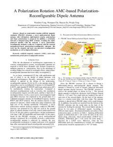
Fig. 1. (a) Shift register based on current-induced DW in a long magnetic stripe, MTJs are used as write and read heads for the DW nucleation and signal detection. (b) Magnetic tracks can be implemented above CMOS to increase the computing speed and reduce the final die area.
high standby power due to the increasing leakage currents as the fabrication node shrinks down to 90 nm or below [13]. Nonvolatile storage technologies are expected to replace the SRAM configuration, and then allow the logic circuits to be instantly ON/OFF and overcome definitely the standby power issue. This integration should not drive important performance degradation. Magnetic RAM (MRAM) is the most promising technology for this purpose, thanks to its infinite endurance, easy integration with CMOS, high sensing speed, etc. [3], [4]. Its switching methods such as field-induced magnetic switching (FIMS), thermally assisted switching (TAS), and spin transfer torque (STT) have been investigated recently for reconfigurable logic circuits ns/bit) [14]–[16]. However, their long switching duration ( and large CMOS area dedicated for the switching makes the gain of zero standby power less attractive. Moreover, the size shrinking of the MTJ cell cannot efficiently help to surmount these limitations [17]. In this paper, we present the first lookup
0018-9464/$26.00 © 2011 IEEE
ZHAO et al.: DOMAIN WALL SHIFT REGISTER-BASED RECONFIGURABLE LOGIC
2967
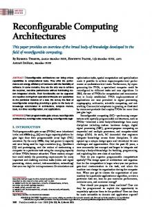
Fig. 2. (a) Domain wall shift register-based magnetic lookup table (DW-LUT). (b) Structure of dual magnetic track shift register: it shares the same DW nucleation (DW nucleation) and I (DW motion), which should not be overlapped. and shift circuits. (c) Signals of I
table based on the DW shift register (DW-LUT) to build reconfigurable logic circuits, which may shrink the final die area and improve the power efficiency compared with conventional SRAM-LUT while keeping high computing and reconfiguration speed. We believe that such a circuit has potential for wide applications. The operations and circuit details of DW-LUT is introduced in Section II. In Section III, we report the transient simulations by using hybrid DW/CMOS 65-nm process and demonstrate its expected high performances in terms of power, speed, and die area. II. DOMAIN WALL SHIFT REGISTER-BASED MAGNETIC LOOKUP TABLE The schematic of the DW-LUT is composed of three main parts [see Fig. 2(a)]. A DW shift register stores the logic circuit configuration; it is associated with a conventional CMOS multiplexer (MUX) [12] for the data selection and a high-speed Sense Amplifier (S.A) for data detection [2], [16]. In order to obtain high computing speed ( GHz) and good hardness to fabrication mismatch/process variations, which are essential requirements for logic application, complementary data storage is used in this DW-LUT. The shift register is based on dual magnetic tracks with a couple of MTJ write heads connected together at the bottom [see Fig. 2(b)]. They nucleate the opposite magnetization (perpendicular or planar) at the two tracks with the same current pulse through the STT switching approach [18]. The magnetic tracks are separated with a number of constrictions or artificial potentials, which can pin the DW at the precise positions in the track [19]. There is an MTJ read head between two nearby constrictions and a couple of MTJs at the same position of the dual tracks presents a logic bit. For example, for a DW-LUT with three inputs, bits are required to be implemented in the DW shift register, which is composed of dual magnetic tracks with constrictions and MTJs. The current pulse drives the DW motion in both the dual magnetic tracks in parallel, which ensures that the storage elements at the same position of the dual tracks are always in the opposite configuration. The S.A is used to
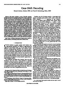
detect the complementary storage information by passing two and ) through the complementary read currents ( heads in the dual tracks [20]. It is important to underline that the current pulses of and should not be overlapped to avoid the DW nucleating and are, and moving errors. The pulse durations of respectively, , which should be long enough to ensure the reliable MTJ switching and DW motion [see Fig. 2(c)]. In order to achieve the best switching/sensing reliability, the size of MTJ write head should be larger than that of read head as lower resistance of MTJ can reduce the rate of breakdown of oxide barrier. In contrast, high resistance with smaller size can improve the sensing performance. This DW-LUT presents first smaller area. For a logic gate MTJs, and with inputs, it requires 2 magnetic stripes, transistors (4 transistors for the bi-directional current source [16] and 7 transistors for the S.A [20]). A conventional LUT based on either 6-T SRAM cell or shift register requires at least transistors [11], [12]. If , 116 transistors are economized and more CMOS economy up to % can be obtained for complex functions with (see Fig. 3). Note that the write transistors are counted in minimum size, which could be achieved by multipower technique, i.e., the write current source is powered by 2.2 V and the other circuits are powered by 1.0 V. Different from CMOS shift register LUT [12], two MUX are used in the DW-LUT to address in parallel the complementary MTJ read heads. This additional CMOS footprint explains that the area benefit of DW-LUT is saturated to % for complex logic functions. As mentioned previously, magnetic tracks and MTJs are implemented above the CMOS circuits. The CMOS footprint is then nearly the die area of final hybrid circuits, which is much larger than dual magnetic tracks. Other tracks can be then integrated in parallel through crossbar architecture in the same DW-LUT [21], which allows it to be embedded with multiconfiguration or multicontext. This makes some new computing paradigms to be implemented with limited CMOS overhead such as run-time reconfiguration [15], [16] and context switching logic circuits [22].
2968
IEEE TRANSACTIONS ON MAGNETICS, VOL. 47, NO. 10, OCTOBER 2011
TABLE I EXPERIMENTAL PARAMETERS INCLUDED IN THE DW MODEL
Fig. 3. Number of function inputs versus number of transistors for DW-LUT and SRAM-LUT. DW-LUT allows complex functions to be implemented with only half die area of SRAM-LUT.
Benefiting from the nonvolatile storage in the magnetic track and high-speed sensing circuit, DW-LUT allows the reconfigurable logic circuits to be instantly ON/OFF and then dissipate nearly zero standby power. The switching power includes two parts: write head switching and DW motion in the magnetic µA) is retrack. For DW motion, low current value ( quired, thanks to the small section surface of thin track film ( nm) even though the critical current density to move DW is as high as A/cm [23]. For DW nucleation, the STT switching of MTJ write head consumes comparatively high power as high current value ( µA) should be applied to obtain short duration [3]. However it is activated only if there is a data change between “0” and “1.” For instance, as “0000” is planned to be stored in the DW shift register, only one time nucleation is needed. For the same purpose, an STT-MRAM-based LUT needs four write current pulses to switch each storage cell [16] and then quadruples the power dissipation. More economy can be achieved for a complex logic function through DW shift mechanism and DW-LUT promises the best power efficiency compared with SRAM-LUT and other nonvolatile LUT. Another important gain of DW-LUT is the (re)configuration speed. As multicontext configurations are implemented, LUT reconfiguration can be simply the change of context address, which could be very fast ns. Besides, the DW motion in a m/s); as the thin magnetic track can be set at high speed ( is 100 nm, the switching dudistance of two constrictions ration is, thus, lower than 1 ns. This speed can be further improved by shrinking , increasing value [23], or using some special DW pining techniques [24]. Extremely high magnetic switching speed of ps can be expected from the theoretical point of view. The shifting mechanism of DW can be also beneficial to speed up LUT reconfiguration and reduce the power dissipation. For example, if the previous configuration stored in the DW shift register is “1010” and new target one is “1000,” only two short pulses (see Fig. 2) are required for the LUT reconfiguration.
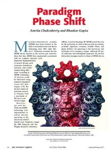
Fig. 4. (a) I bidirectional current pulses nucleate the DW or data change current pulses move the DW in the magnetic in the write heads. (b) I tracks. (c) Input data A. (d) Input data B. (e) Output of DW-LUT after the logic computation.
III. SIMULATION OF DW-LUT By using a compact model integrating DW nucleation, shifting and sensing operations [25], and CMOS 65-nm design kit [26], a 2-input DW-LUT has been successfully simulated. (CoFeB(6)/MgO (0.85)/CoFeB (1.2)) MTJ write head is used for the DW nucleation through STT switching mechanism and a 465 µA allows the magnetization switching current pulse in ns. In the CoFeB magnetic strip, we have considered four storage elements (constrictions) for 2-input logic gate; 95 µA can move the DW across each a current pulse storage element in 2 ns. Table I shows the major experimental parameters used in the compact model. Fig. 4 shows the transient simulation of 2-input DW-LUT, which is first configured to AND logic gate and then reconfigured to XOR gate after 200 ns. The logic data stored in the dual track DW shift register are initialized to “0001” with two pulses and four pulses in ns. For the reconfiguration, pulse and two data should be changed to “0110” with one pulses benefiting from the shifting mechanism and the reconfiguration delay is reduced down to ns. With only three pulses and six pulses, the whole operation consumes fJ. a low energy The simulation shown in Fig. 5 confirms the high computing speed of DW-LUT, which is the magnification of evaluation operation at the moment when the DW-LUT has been reconfigurated to XOR logic gate (see also Fig. 4). The output can be updated in less than 500 ps after the activation of enabled
ZHAO et al.: DOMAIN WALL SHIFT REGISTER-BASED RECONFIGURABLE LOGIC
Fig. 5. Latency to obtain the computed results is less than 500 ps. There are only dynamic currents during computing operation.
computing signal “EN.” It is comparable with the speed of conventional LUT [11], [12]. A precharge sense amplifier is used in the DW-LUT (see Fig. 2) for complementary data detection, which performs low power, high speed, and high reliability [20]. There is no stationary current passing through the circuit during µA (Isense0) and computing and the peak current values µA (Isense1) for the two branches (see Fig. 2) dissipate aJ for the computing operation. an extremely low energy IV. CONCLUSION AND PERSPECTIVES In this paper, we have presented the first concept of DW-LUT based on dual track DW shift register, which may be used as the elementary block to develop new generation of reconfigurable logic circuits with zero standby power, run-time reconfiguration, and instant ON/OFF capability. Its high performances such as high speed ( GHz), low power, and smaller die have been confirmed through hybrid DW/CMOS 65-nm simulations. Other logic circuits based on DW shift register such as nonvolatile flip-flop [27] and spin NAND/NOR logic [28] are under investigation in our laboratory. A prototype of DW-LUT based on a 45-nm fabrication node is under development. ACKNOWLEDGMENT The authors would like to acknowledge the financial support from French national program ANR-SPIN, Nano2012 project with STMicroelectronics, and European FP7 program through contract MAGWIRE (257707). REFERENCES [1] C. Chappert, A. Fert, and F. N. Van Dau, “The emergence of spin electronics in data storage,” Nat. Mat., vol. 6, pp. 813–823, 2007.
2969
[2] S. Sugahara and J. Nitta, “Spin-transistor electronics: An overview and outlook,” Proc. IEEE, vol. 98, no. 12, pp. 2124–2154, Dec. 2010. [3] S. H. Kang, “Development of embedded STT-MRAM for mobile system-on-chips,” IEEE Trans. Magn., vol. 47, no. 1, pp. 131–136, Jan. 2011. [4] B. N. Engel et al., “A 4-Mb toggle MRAM based on a novel bit and switching method,” IEEE Trans. Magn., vol. 41, no. 1, pp. 132–136, Jan. 2005. [5] S. S. Parkin, M. Hayashi, and L. Thomas, “Magnetic domain-wall racetrack memory,” Science, vol. 320, pp. 190–194, 2008. [6] L. Thomas, R. Moriya, C. Rettner, and S. S. Parkin, “Dynamics of magnetic domain walls under their own inertia,” Science, vol. 330, pp. 1810–1813, 2010. [7] International Technology Roadmap for Semiconductors 2009. [8] M. Hayashi, L. Thomas, R. Moriya, C. Rettner, and S. P. P. Parkin, “Current-controlled magnetic domain-wall nanowire shift register,” Science, vol. 320, pp. 209–211, 2008. [9] S. Kukami et al., “Low-current perpendicular domain wall motion cell for scalable high-speed MRAM,” in VLSI Symp., 2009, pp. 230–231. [10] S. Ikeda et al., “Tunnel magnetoresistance of 604% at 300 K by suppression of Ta diffusion in CoFeB/MgO/CoFeB pseudo-spin-valves annealed at high temperature,” Appl. Phys. Lett., vol. 93, p. 082508, 2008. [11] S. Brown, R. Francis, J. Rose, and Z. Vranesic, Field Programmable Gate Arrays. Norwell, MA: Kluwer, 1992. [12] 2010 [Online]. Available: www.xilinx.com, Spartan-3 FPGA series [13] N. S. Kim, “Leakage current: Moore’s law meets the static power,” Computer, vol. 36, pp. 68–74, 2003. [14] W. S. Zhao, E. Belhaire, C. Chappert, and P. Mazoyer, “Power and area optimization for run-time reconfiguration SOPC based on MRAM,” IEEE Trans. Magn., vol. 45, no. 2, pp. 776–780, Feb. 2009. [15] W. S. Zhao et al., “TAS-MRAM based non-volatile FPGA logic circuit,” Proc. IEEE-ICFPT, vol. 45, no. 2009, pp. 153–160, 2007. [16] W. S. Zhao et al., “Spin transfer torque (STT)-MRAM based run time reconfiguration FPGA circuit,” ACM Trans. Embedded Comput. Syst., vol. 9, no. 2, 2009, article 14. [17] S. Ikeda et al., “A perpendicular-anisotropy CoFeB-MgO magnetic tunnel juction,” Nat. Mater., vol. 9, pp. 721–724, 2010. [18] S. Mangin et al., “Current-induced magnetization reversal in nanopillars with perpendicular anisotropy,” Nat. Mater. 5, pp. 210–215, 2006. [19] C. Burrowes et al., “Non-adiabatic spin-troques in narrow magnetic domain walls,” Nat. Phys., vol. 6, pp. 17–21, 2010. [20] W. S. Zhao, C. Chappert, V. Javerliac, and J. P. Noziere, “High speed, high stability and low power sensing amplifier for MTJ/CMOS hybrid logic circuits,” IEEE Trans. Magn., vol. 45, no. 10, pp. 3784–3787, Oct. 2009. [21] W. S. Zhao et al., “Design considerations and strategies for high-reliable STT-MRAM,” Microelectron. Rel. Jul. 2011, doi:10.1016/j.microrel.2011.07.001. [22] S. M. Scalera and J. R. Vazquez, “The design and implementation of a context switching FPGA,” Proc. IEEE-FCCM, pp. 78–85, 1998. [23] A. Thiaville, Y. Nakatani, J. Miltat, and Y. Suzuki, “Micromagnetic understanding of current-driven Fast domain wall motion in magnetic comb structures,” Europhys. Lett., vol. 69, pp. 990–996, 2005. [24] E. R. Lewis et al., “Fast domain wall motion in magnetic comb structures,” Nat. Mater., vol. 9, pp. 980–983, 2010. [25] W. S. Zhao, J. Duval, D. Ravelosona, J.-O. Klein, and C. Chappert, “A compact model of domain wall propagation for logic and memory design,” J. Appl. Phys., vol. 109, p. 07D501, 2011. [26] CMOS 065 General Power Design Rule Manual 2010, ST Microelectronics, Bulk CMOS Process. [27] N. Sakimura, T. Sugibayashi, R. Nebashi, and N. Kasai, “Nonvolatile magnetic flip-flop for standby-power-free SoCs,” in Proc. IEEE-CICC, , USA, 2008, pp. 355–358. [28] B. Behin-Aein, D. Datta, S. Salahuddin, and S. Datta, “Proposal for an all-spin logic device with built-in memory,” Nat. Nanotechnol., vol. 5, pp. 266–270, 2010.