Dots and Incipient based Fingerprint Matching Scheme using FMM and Delaunay Triangulation Satyabrata Swain*, Banshidhar Majhi, Ratnakar Dash, and Pankaj Kumar Sa
Department of Computer Science and Engineering, National Institute of Technology Rourkela, India Email:
[email protected].{bmajhi.ratnakar.pankajksa}@nitrkl.ac.in Abstract-Automated Fingerprint Identification Systems (AFIS) currently rely only on Levelland Level 2 features. But these features are not much helpful for forensic experts as the experiment deals with partial to full print matching of latent fingerprint. Forensic experts takes the advantage of extended feature proposed by "Committee to Define an Extended Fingerprint Feature Set" (CDEFFS). This paper presents extraction technique of two extended features, dots and incipient ridges by tracing valleys. We have found starting points on the valley by analyzing the frequencies present in the fingerprint. Valley are traced from the starting point using first marching method ( FMM ). An intensity checking method is used for finding these feature points. Then matching are done by establishing spatial relation with minutiae using Delaunay triangulation. Extensive simulation is carried out in MATLAB environment to show the superiority of the proposed feature extraction technique over state of art. Accuracy of the proposed feature extraction scheme also has been shown using special database 30 and lIlT Delhi database. Keywords-Fingerprint;Extended feature;Level 3 feature;Dots and incipient;Feature extraction;Matching;Delaunay triangulation
I.
INTRODUCTION
A number of biometric traits have been developed and several of them are being used in variety of applications. Among these, fingerprint, face, iris, speech and hand geometry are most commonly used system. Fingerprint recognition has been accepted as a reliable person identification technique for almost hundred years due to their uniqueness and immutability. Although fingerprint verification is usually associated with criminal identification and police work, now-a-days it has become more popular in civilian and commercial applications, such as access control, financial security and verification of firearm purchasers, etc. Skin on human fingertips, called as fingerprint, contains ridges and valleys (furrows) which together forms distinctive patterns. These patterns are fully developed in the womb and are permanent throughout whole lifetime. Fingerprint is having rich set of feature. These features are generally categorized into three levels. Level 1 features are defined by fingerprint ridge flow ( ridge pattern types, ridge orientation field, and singular points ). Level 2 features, also called as Galton characteristics or minutiae, such as ridge bifurcations and ridge endings. Level 3 features are defined as fingerprint ridge dimensional features. Pores, dots, incipient ridges, ridge edge shapes, breaks, creases, scars, and other permanent details are defined as level 3 ( named as extended feature by CDEFFS ) features. Level 1 features are not unique, so it is mainly used for type classification ( e.g. whorl, left loop, right loop, and
arch ). Level 2 features are quite discriminative and stable, so successfully used in AFIS. In case of latent print examination ( full to partial matching ), level 2 features are not sufficient as the area of the fingerprint surface is very small (so contains less number of minutiae ). According to the forensic experts Level 3 features are permanent, immutable, unique, and also provide discriminatory information for human identification. However, level 3 feature can be captured using high resolution sensor ( 2: 1000 pixels per inch (ppi) ) where as level 2 can be captured using 500 ppi sensor. Dots and incipient ridge are present in valley in between two ridge. Its size is less than 0.02 inch, where as incipient ridge is thinner than local ridge width. A lots of work has been reported on level 3 feature. Anil K. Jain et ale [2] proposed a method for extracting pores and ridges using wavelet transform and Gabor filters. N. Manivanan et ale [3] proposed pore extraction method using highpass and correlation filtering. Yi Chen et ale [1] proposed a method for dots and incipient ridge extraction by using local phase symmetry and continuous skeletonization of valley, but this skeletonization process is computationally expensive. Moreover, level 3 feature are considered as level 2 feature and is added to the minutiae set while matching using BOZORTH3 of NBIS [11] matching tool. However, in this paper our technique has been used for the extraction of dots and incipient ridges by tracing valleys. While matching, different sets of feature vector are constructed from level 2 and level 3 feature using Delaunay triangulation. Rest of the paper is organized as follows: Section II explains extraction of starting point. Section III gives description on FMM. Section IV introduces extraction technique and Section V describes new matching technique. Finally experimental result and conclusion are presented in section VI and VII respectively.
II.
STARTING POINT EXTRACTION
Our primary objective is to select a set of points on valleys from which tracing of valley can be started. Tracing is done in such a way that each traced point is approximately on the middle of that valley. Tracing needs a location of a starting point. Better starting point provides a better tracing. A window is taken from the middle portion of the fingerprint. X-signature [5] of the window is calculated for analyzing the frequencies present in the window. This window consists of signals with different frequencies. Ridge valley pattern of a fingerprint image can be represented as a sinusoidal wave with constant frequency. In signal processing concept if the speed of the signal is equal to wavelength, then the frequency component contains only first harmonic. The frequency is calculated as,
_ Speed == Ar + Av == 1 Frequency - W ave l eng th /\'
Entropy == -
(1)
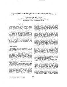
where Ar and Av is the width of the ridge and valley respectively. The above frequency represents the first harmonics. To extract the ideal signal, all the frequencies above and below the first harmonics are suppressed. The lower frequency component is due to the presences of noise along with dots and incipient ridge on the valley and the high frequency component is due to noise along with pores on the ridges. The ideal signal is obtained by window based filtering with its corresponding power spectrum. The processed X-signature Fig. 1(d) is approximately close to a signal which contains only single frequency. The peak of the processed X-signature will be the center of the valley. As we need a starting point on each of the valley on a fingerprint, window is taken from the middle of the image and vertically moved down. The reason for selecting the window at the middle of the image is to cover the maximum number of valleys with minimum number of windows. The problem may arises near singular point and delta region. In order to get a starting point in these regions, we shift the window towards left and right horizontally until a starting point is identified.
i=255
2:=
P j log 2 P j
(2)
i=O
where Pj is the probability that the difference between two adjacent pixel is i. After finding the starting point, the next job is to trace the valley using FMM. FMM [9] is utilized for image segmentation. In this paper, we have used FMM for tracing valleys. Following section explains the concept of FMM. III.
FIRST MARCHING METHOD
The fast marching method is a numerical method for solving boundary value problems of the Eikonal equation. It is a special case of level set method for computing the propagation of front where the speed depends on the local position and is extremely fast scheme for solving the Eikonal equation. We have explained the whole concept in following steps: A. Interface Propagation Given an arbitrary region, the interface is defined as the curve, or surface, separating the area inside of the region from the area outside of the region. Interface propagation is defined as the motion of the interface in normal direction. For motion, a velocity is required which is described as 1) a component depends on the local property of the interface, 2) a component belonging to global properties of the surface, 3) and a component independent of the surface. B. The Boundary Value Formulation An interface which is strictly expanding or contracting is known as the boundary value formulation. Eikonal equation establish a relation between arrival function and speed of the interface as follows.
I\7TI F == 1 Fig. 1. (a) window from the middle part of fingerprint, (b) X-Signature of the window, (c) Power spectrum of the X-Signature, (d) Processed X-Signature
The location of the starting point on the valley is ensured by the above mentioned technique Fig. 1 . However, the point may located either on white area or on black area (dots or incipient ridge). To know that, an intensity checking procedure is used. The intensity of the point is compared with a threshold (experimentally calculated) and if it is less than threshold then it is discarded as starting point but can be further processed for dots or incipient ridges detection. If intensity is above the threshold then entropy of the neighborhood of the point is calculated using (2). Entropy based checking is done to know the presence of white noise on the dots and incipient ridge. If the starting point is on the white patch (noise) in the dots then entropy of the neighborhood will be higher. So if entropy of the neighborhood is higher than a threshold value then the point is discarded otherwise it is considered as starting point.
(3)
where T is the arrival function and F is the speed of the interface. Arrival function has one more dimension than the surface that is if surface is in R 2 then the arrival function wiil be in R 3 . For the boundary value formulation, interface is expanding or contracting if F > 0 and F < 0 respectively. Fast Marching Method is the special case where the interface move in one direction, where as the initial value formulation does not impose this restriction.
c.
Initial Value Formulation
In the initial value formulation, an interface may propagate back to points it has already propagated. It follows that the speed function F is no longer strictly greater or strictly less than 0 for all time. In order to facilitate this more general definition, a level set function is required.
D. Level set method and its solution Given an initial position for an interface T, where T is a closed curve in R 2 , and a speed function F, which gives the speed of T in its normal direction, the level set method takes the perspective of viewing T as the zero level set of a function (x, t == 0) from R 3 to R. That is (x, t == 0) == ±d, where d is a distance from x to T, and the plus (minus) sign is chosen if the point x is outside (inside) the initial surface T. Using chain rule, an evolution equation for the interface can be written as, (4)
where is the level set function, F is the speed function, and t represents the first derivative of with respect to t. Solution of above equation is given by, ~:+-1 1,)
==
~. - ~t(min (D~X¢ 0)2 max(D~Y 0))1/2 1,)
1,)
,
-~t(max (DijX, 0)2
1,)'
+ min (D~Y, 0)2)1/2
E. Fast Marching Level Set Method If F == F(x, y, z) > 0 is a speed function, a monotonically advancing front whose level set equation is t + F(x, y, z) \7 == 0 is given by, 1
(x, t == 0) ==
T
1)
(5)
where the speed is F == 1 and the difference operator is defined as D~x == (i+1,j - i,j) / ~t. This solution is for evolution of all the level sets corresponding to the front itself. So this is computationally expensive solution. An efficient technique called "narrow band approach" which works only in a neighborhood of the zero level set. Using this concept, grid points are divided into alive, land mines or far away, depending on whether they are inside the band, near its boundary, or outside the band, respectively. One - cell version of this leads to fast marching method.
1
The important aspect of constructing Fast Marching Level Set Method algorithm is to estimate propagation of front in upwind manner with speed F ij and its direction is normal to each grid point. Here the set of grid points j == 1 correspond to y axis, and we assume that F ij > O. So the algorithm solves the above eq by increasing the value of T from its smallest value. Front will sweep in upwind direction by considering a set of points in the band around the existing front, freezing the values of existing points and bringing new ones into the narrow band structure. The next step is to select the grid point to be updated within the current narrow band. The algorithm [9] is stated in following steps
(6)
In two-dimensional case in which the interface is a propagating curve, zero level set is evolving above xy-plane. T(x, y) be the time at which the curve crosses the point (x,y). The surface will satisfy Eikonal equation (3). According to (3), gradient of arrival time surface is inversely proportional to the speed of the front. Using approximation of the gradient, the solution of the above equation is given as,
where T(x, 0) == O. Rouy and Tourin find a less diffusive iterative algorithm for computing the solution for Eikonal equation which is given as,
Intialize a) (Alive points: shaded points): Let A be the set of all grid points i,j == 1; set T i ,l == 0.0 for all points in A. b) (Narrow band points: circles): Let Narrow Band be the set of all grid points i, j == 2; set T i ,l == ;~. for all points in Narrow Band. c) (Far away points: rectangles): Let Far Away be the set of all grid points i, j > 2; set Ti,j == 00 for all points in Far Away. Marching Forward a) Begin Loop: Let (imin,jmin) be the point in Narrow Band with the smallest value for T. b) Add the point (imin,jmin) to A; remove it from NarrowBand. c) Tag as neighbors any points (i min -1, jmin), (i min + 1, jmin), (i min , jmin1), (i min , jmin + 1) that are either in Narrow Band or Far Away. If the neighbor is in Far Away, remove it from that list and add it to the set Narrow Band. d) Recompute the values of T at all neighbors according to Equation 8, selecting the largest possible solution to the quadratic equation. e) Return to loop. ~J
2)
The important aspect of constructing Fast Marching Level Set Method algorithm is to estimate propagation of front in up- wind manner with speed Fij and its direction is normal to each grid point. IV.
FEATURE EXTRACTION
We have used FMM for tracing valleys of the fingerprint. Instead of taking initial point ( alive point as defined in FMM ) along y-axis as FMM, the set of points are taken extracted in section II. We are able to propagate toward right and left of the saddle point which are normal to the interface in inticlockwise and clockwise direction respectively. While tracing, we are taking a window around the traced point. If I( i, j) < Q, where I (i, j) is any pixel in the window, and Q is a gray level intensity value, then a connected component is constructed by considering the range of the intensity value 0 to Q. These connected component includes dots, ridge incipient and noise. CDEFFS standardized that the size of dots and incipient ridges are less than 0.02 inch. So all the extracted components whose size is more than 0.02 inch ( part of a ridge ) are discarded. Centroid of rest of the extracted component and its direction are calculated. The fingerprint with traced valley and the
extracted dots and incipient are shown in Fig 2 (a) and 2 (b) respectively.
Yf ¢(a,j3) = V(a - j3)fJ-l(a - j3f
d(X, Y) = V(X - Y)S-l(X -
(9)
Where 8- 1 and f)-I are covariance matrix, (X - y)T and (a - f3) T are transpose matrix for edge and angle respectively. Triangle pair is considered as a matching pair if d(X, Y) and ¢( a, f3) are less than the calculated threshold values. This process is carried out for all triangle pairs. Fig. 2. (a) Traced image, (b) Dot and incipient are shown in '*' and '+' respectively
V.
MATCHING
Minutiae are extracted by using a commercial software called MINDCT of NIST Biometric Image Software (NBIS) [11]. Level 2 and level 3 feature have been used for full to partial matching. Due to uniqueness, local stability, structural stability and linear time complexity, Delaunay triangulation [14] [13] gives very good performance in matching. Delaunay triangulation has already been used with level-2 features for fingerprint indexing and identification. However, we have used Delaunay triangulation not only for matching but also for establishing relation between level 2 and level 3 features. From minutiae set, Delaunay triangle is formed using following steps. •
Given n minutiae points, a Voronoi diagram is constructed in such a way that each region of the diagram will contain one minutia.
•
Delaunay triangulation is constructed by joining the minutiae in the neighborhood Voronoi regions.
Delaunay triangle is constructed by using minutiae set. Delaunay triangulations which is constructed from input image is compared with the stored triangulation ( gallery ) by using set of features. If input has K triangle and template has L triangle, then total number of comparison is K x L. In addition to that, there is a chance that may not satisfy structural stability. We have proposed an efficient method which takes K + L comparison and will also maintains structural stability. For input image three sides of each triangle are sorted continuously in an array A. All the triplet are placed in such a way that A[i] > A[i + 1] > A[i + 2]' A[i] > A[i + 3], i == 1 to M, i%3 == 1, (i + 1)%3 == 2, (i + 2)%3 == 0, M == 3 x K, where A is an array which contains the sides of triangle, M is size of array and K is the number of triangle. Similar procedure has been followed for storing template information in array T which contains N number of minutiae where N == 3 x Land N > M. Before matching, a preliminary matching has been carried out as described in Algorithm 1. In this algorithm, all compatible pairs from A and T are figured out and considered for matching. Mahalanobis distance for edge and angle of the triangle pair are calculated. Edge triplet of a compatible pair are stored in X and Y, angles are stored in a and f3. Then the Mahalanobis distance can be calculated as,
Matching is done using level 3 feature followed by level 2 feature. While matching using level 3 feature, spatial relation has been established with the neighboring minutiae. As dots and incipient ridges are present on the valley, it will lie either inside the triangle or on the edge of the Delaunay triangle which is already constructed using minutiae. We have compared only those triangle which contains these level 3 features. If k and l are the number of dots and incipient ridges of input and template image respectively then total number of comparison is k x l, where k x l < M x N. Let {lil, li2, li3} and {aI, a2, a3} are the edges and angle of triangle from input image where, lil > li2 > li3 and lij is nonadjacent to aj, j == 1,2,3. When a dot is present inside the triangle then a new set of feature vector is extracted by connecting the dots to each corner of the triangle. These features are length of line connecting dot to each corner and two angles sustained at each corner. When III is connecting to dot and aI, a12 and a13 are sustained at al. This is shown in Fig. 3. When dot is on the edge of the triangle then length of the line connecting to dot and comer of triangle is considered as feature vector. Similar convention has been adopted for gallery set where edge and angle are defined as {ltl' lt2, lt3} and {f3l, f32, f33} respectively. There is a match of a input triangle with gallery triangle if the following conditions are satisfied, Iij (aj Il j (axyl - f3xyl) -
- Itj < T h_length - f3j) < Th_angle1 Tl j < Th_length_dot (a xy 2 - f3xy2) < Th_angle_dot
(10)
Where j=l, 2, 3 and x == 12,3, x -# y1 -# y2. Th_length, Th_angle1, Th_length_dot and Th_angle_dot are calculated threshold values. The above conditions are applicable if level 3 features are inside the triangle. If it is on the edge of the triangle, then third equation of equation 10 is modified as Imllo - TmllO - Imllo - Tml20 < th_midlength and last equation is dropped. Sum rule has been adopted for fusing level 2 and level 3 match score. VI.
EXPERIMENTAL RESULTS
In this paper we have matched between partial to full fingerprint using dots and ridge incipient. We have used NIST special database 30 (SD30) [12] and Rural Indian Fingerprint Database [7] of lIlT Delhi for performance evaluation. All images in SD30 are taken in constraint environment and images in lIlT database are taken in unconstraint environment. The earlier database includes 72 tenprint cards from 36 users, 10 fingers per user and 2 impressions per finger, scanned
Algorithm 1 Triangle Pair Selection Require: A[l : M]' T[l : N] Ensure: M atched_Array_Index [1 : 2 x K] contains all the matching pair index of A and T 1: Initialize: M atched_Array_Index[l : 2 x K] == 0, j == 1 ,p == 1, K == M /3 2: for k +- 1 to K do 3: if A[i] ~ T[j]UA[i+1] ~ T[j+1]UA[i+2] ~ T[j+2] then 4: Matched_Array_Index[p] == i 5: M atched_Array_Index [p + 1] == j 6:
7: 8: 9:
10: 11:
12: 13: 14:
p == p + 2 i == i + 3 j == j + 3
else if A[i] < A[i i == i + 3 else j == j + 3 end if end for
+ 1]
they have cropped the partial print manually but in our case we have divided a full print into non-overlapped partial print. This method ensures that a partial print contain a region from all parts of a full fingerprint. Our method shows superiority over Yi Chen [1] method.
then
Fig. 4. ROC curves are plotted for partial to full fingerprint by cropping the partial print using non-overlapped block and random cropping using SD 30 database (a) non-overlapped cropping using only level 2 features, (b) nonoverlapped cropping using level 2 and level 3 features (c) random cropping using only level 2 features (d) random cropping using level 2 and level 3 features
VII. Fig. 3. (a) Delaunay Triangle constructed using Minutiae, (b) Features Extracted from triangle
at both 500ppi and 1000ppi. The latter includes each 150 fingerprint of right hand and left hand index fingerprint image of urban and rural people and 10 print per each individual. So the total number of print is 3000( (75 x 2 x 10) + (75 x 2 x 10)). For performance measure, two experiments have been conducted for each database. In the first experiment on SD30, the first impression of each fingerprint is divided into 16 nonoverlapping block of size 350 x 350 and rest pixels at boundary are discarded. The total number of genuine and impostor match are 5760 and 2067840 respectively. Similarly, in case of Rural Indian Fingerprint Database, the first image is divided into 12 non-overlapping block of size 150x 150 and rest pixels are discarded at boundary. Number of probe image is 3600(300x 12). Total number of genuine and impostor match are 3600 and 1076400 respectively. In the above case, we are taking non-over lapped partial print for matching against full print assuming that the matching is a partial to full matching. However, above case is not true in case of live data. For that we have randomly cropped 10 partial prints from the first impression and match them against second full impression. The total number of genuine and impostor scores are 3600 and 1292400 in case of NIST database, and 3000 and 897000 number for lIlT Delhi Fingerprint database respectively. Fig. 4 and Fig. 5 shows the acceptance rate of our approach with SD30 and IIITD database respectively. We have shown the result using only level 2 feature and level 2 along with level 3 feature. Accuracy of proposed method has been compared with Yi Chen [1] method in Table VII. In [1],
CONCLUSION
In this paper, a novel approach for fingerprint identification using two extended level 3 features, dots and incipient ridges have been proposed. First marching method with an intensity based checking is done for feature extraction. The Partial to full print matching is performed by taking non-overlapped block and random block. The use of Delaunay triangle for matching enhances the matching performance. The performance measures such as GAR with standard databases shows the efficacy of the proposed feature extraction and fusion scheme over the state of the art techniques. The proposed pattern matching technique will not only benefit forensic experts but also can be used as Next Generation Identification Technology (NGI). A new feature fusion technique with the proposed matching may help to provide better classification accuracy. REFERENCES [1]
Chen, Yi, and Anil K. Jain. "Dots and incipients: extended features for partial fingerprint matching." In Biometrics Symposium. IEEE 2007, pp. 1-6.
[2]
Jain, Anil, Yi Chen, and Meltem Demirkus. "Pores and ridges: Fingerprint matching using level 3 features." ICPR 2006, 18th International Conference on Pattern Recognition. IEEE, 2006. pp. 477-480.
[3]
Manivanan, N., S. Memon, and W. Balachandran. "Automatic detection of active sweat pores of fingerprint using highpass and correlation filtering." Electronics letters 46 vol 18 pp. 1268-1269, 2010.
[4]
Zhao, Qijun, Jianjiang Feng, and Anil K. Jain. "Latent fingerprint matching: Utility of level 3 features". MSU Techical Report 8. pp. 130, 2010. Arpit, Devansh, and Anoop Namboodiri. "Fingerprint feature extraction from gray scale images by ridge tracing". In Biometrics (IJCB), 2011 International Joint Conference on. 2011,IEEE, pp. 1-8.
[5]
[6]
"CDEFFS, ANSIINIST Committee to Define an Extended Fingerprint Feature Set" http://fingerprint.nist.gov/standard/cdeffs/index.html/.
TABLE 1.
ACCURACY COMPARISON OF PROPOSED APPROACH WITH YI CHEN'S APPROACH FOR LEVEL USING SD 30 AND lIlT DELHI DATABASE.
Database NIST 30 lIlT Delhi
Proposed Approach Non-Overlapped 1eve12 Leve12 + 3 Feature Feature 82 91 79 89
Random Cropping Leve12 Leve12+3 Feature Feature 92 85 82 90
Fig. 5. ROC using lIlT Delhi database (a) random cropping using level 2 and level 3 features (b) non-overlapped cropping using only level 2 features (c) non-overlapped cropping using level 2 and level 3 features (d) random cropping using only level 2 features
Chen Approach [1] Manual Cropping Leve12 Leve12 +3 Feature Feature 82 87 79 85
2
AND LEVEL
2 WITH
LEVEL
3 FEATURES
Random Cropping Leve12 Leve12 +3 Feature Feature 85 90 82 85
[7]
Puri, C., K. Narang, A. Tiwari, M. Vatsa, and R. Singh. "On analysis of rural and urban indian fingerprint images". In Ethics and Policy of Biometrics. Springer Berlin Heidelberg, 2010 pp. 55-61.
[8]
Jain, Anil K., Yi Chen, and Meltem Demirkus. "Pores and ridges: Highresolution fingerprint matching using level 3 features". Pattern Analysis and Machine Intelligence. IEEE Transactions on 2, vol. pp. pp. 115-27.
[9]
Sethian, James A. "A fast marching level set method for monotonically advancing fronts" Proceedings of the National Academy of Sciences 93, vol. 4 pp. 1591-1595, 1996.
[10]
Dicker, Jeff. "Fast marching methods and level set methods: an implementation". PhD diss., University of British Columbia, 2006.
[11]
"NIST Biometric Image Software http://www.nist.gov/itl/iad/ig/nbis.cfm
[12]
"National Institute of Standards and Technology, "NIST Special Database 30," http://www.nist.gov/srd/nistsd30.htm.
[13]
Liu, Ning and Yin, Yilong and Zhang, Hongwei. "A fingerprint matching algorithm based on Delaunay triangulation net." Computer and Information Technology, 2005. CIT 2005. The Fifth International Conference on IEEE pp. 591-595, 2005.
[14]
Zheng, Jian-De, Yuan Gao, and Ming-Zhi Zhang. "Fingerprint matching algorithm based on similar vector triangle." Image and Signal Processing, 2009. CISP' 09. 2nd International Congress on. IEEE, 2009.
(NBIS)
4.2.0",