IEEE TRANSACTIONS ON APPLIED SUPERCONDUCTIVITY, VOL. 25, NO. 3, JUNE 2015
5400704
Transposition-Based Connection Scheme and Joint Box Concept for a Tri-Axial HTS Power Cable Sung-Kyu Kim, Minh-Chau Dinh, Jongho Choi, Minwon Park, In-Keun Yu, Sangjin Lee, and Kideok Sim
Abstract—Tri-axial high temperature superconducting (HTS) power cables are being developed to maximize their advantages, which include reducing amount of HTS wires, having a lowleakage magnetic field, and being compact compared to different types of HTS power cables. However, a drawback of HTS power cables is their inherent imbalance impedance, which is due to an asymmetrical structure on each phase. To solve this problem, the phases must be transposed. The authors designed a distribution class tri-axial HTS power cable, as well as a transposition-based connection scheme for the cable. The phases of the cable were connected to each other via transposition through their crossconnections. This was achieved with an insulated support structure with three walled-off areas for insulation between three the phases, as well as transposition conductors, including copper base and HTS wires. In this paper, a distribution class tri-axial HTS power cable and a connection scheme for it are designed. The results, including the transposition-based joint box design, are described in detail. The connection scheme will be applied to the joint box of the cable for high-capacity and long-distance transmission. Index Terms—High temperature superconducting (HTS) power cable, imbalance impedance, joint box, transposition, tri-axial.
I. I NTRODUCTION
I
N RECENT years, various designs of high temperature superconducting (HTS) power cables have been developed in coaxial, triad, and tri-axial type power cables due to their advantages compared to conventional copper cables. HTS power cables have already been connected to real utility grids [1]. Of these, the tri-axial HTS cable is expected to most effectively solve upcoming power issues, such as the increasing demand for electricity and the limited space of power corridors. The tri-axial HTS power cable has many advantages, including a reduced amount of HTS wires due to elimination of the HTS shield layers, and compact low-heat invasion, which results from the multi-layered structure of the three phases [2]–[5]. In spite of its advantages, unlike other types of HTS power cables, the tri-axial HTS power cable has an inherent imbalance impedance between the three phases due to differences in the radius of the three phases of conducting layers. The imbalance of
Manuscript received August 12, 2014; accepted October 13, 2014. Date of publication November 20, 2014; date of current version January 21, 2015. This work was supported by Changwon National University in 2013–2014. S.-K. Kim, M.-C. Dinh, J. Choi, M. Park, and I.-K. Yu are with the Department of Electrical Engineering, Changwon National University, Changwon 641-773, Korea (e-mail:
[email protected]). S. Lee is with the Division of Energy and Electrical Engineering, Uiduk University, Gyeongju 780-713, Korea (e-mail:
[email protected]). K. Sim is with the Korea Electrotechnology Research Institute, Changwon 642-120, Korea (e-mail:
[email protected]). Digital Object Identifier 10.1109/TASC.2014.2371929
currents caused by the impedance, creates additional losses and a large leakage field in the cable, in addition to degrading the quality of the electric power. To solve the imbalance impedance problem, it is necessary to transpose the phases on the cable [6], [7]. Hence, a distribution class tri-axial HTS power cable and a transposition-based connection scheme for the cable are designed. An impedance matching program to calculate the impedances is developed and used in the design process of the cable [8]. A transposition-based connection scheme is proposed and realized through a support structure with an insulation function and transposition conductors with a connection function between phases. The support structure has three walled-off areas to insulate the three phases as well as a center hole to pass the cryogen. The transposition conductors are composed of tube-type copper blocks to connect with the termination of each phase, a stair-type copper block to connect phases to each other, in which two blocks are one unit; and HTS wires to transfer the current. In this paper, the distribution class tri-axial HTS power cable and the joint box, including the connection scheme, have been designed with an emphasis on the transposition with minimum joint loss for the cable. The features of the joint box are described in detail. The design of the joint box will be reflected in a tri-axial HTS power cable system to achieve a high-capacity, long-distance superconducting cable system.
II. D ESIGN OF A T RI -A XIAL HTS P OWER C ABLE A. Design of the Electrical Insulation For the electrical insulation design of a tri-axial HTS power cable, there are three different types of methods considering withstand voltage and minimum breakdown strength for AC, lightning impulse and partial discharge (PD). In reference to the “Standard Technical Specifications of KEPCO” for a 22.9 kV class power cable, AC and lightning impulse withstand voltages and system maximum AC voltage are 80 kV, 150 kV, and 25.8 kV, respectively. The insulation of the tri-axial HTS power cable is designed using polypropylene laminated paper (PPLP) on the basis of the withstand voltages and minimum breakdown strengths, which have been measured in previous research results [9]. The processes of insulation design for AC, impulse, and PD are shown in Fig. 1. Each insulation design formula for each of the three kinds of insulation design methods and the designed insulation thicknesses of the 22.9 kV class triaxial HTS power cable are shown in Table I. The insulation thickness of the cable was chosen to be 4.0 mm for all phases.
1051-8223 © 2014 IEEE. Personal use is permitted, but republication/redistribution requires IEEE permission. See http://www.ieee.org/publications_standards/publications/rights/index.html for more information.
5400704
IEEE TRANSACTIONS ON APPLIED SUPERCONDUCTIVITY, VOL. 25, NO. 3, JUNE 2015
Fig. 2.
The flow chart of design process for the tri-axial HTS power cable. TABLE II R ELATED E QUATIONS FOR I MPEDANCE M ATCHING OF 22.9 kV T RI -A XIAL HTS P OWER C ABLE
Fig. 1. The processes of insulation design for AC, impulse and PD design. TABLE I I NSULATION D ESIGN F ORMULA AND D ESIGNED I NSULATION T HICKNESS FOR 22.9 kV T RI -A XIAL HTS P OWER C ABLE
TABLE III D ESIGN PARAMETERS OF THE T RI -A XIAL HTS P OWER C ABLE
B. Design of the Tri-Axial HTS Power Cable Here, we discuss the design stage of the distribution class triaxial HTS power cable. From the inside, the tri-axial HTS power cable consists of a hollow former, a single-phase HTS layer per phase and a copper shield layer in the form of a multi-layer. Each HTS conducting layer and copper shield layer are separated for electrical insulation using PPLP, and each is composed of twisted wires along the same axis. The cable was designed using the impedance matching program based on LabVIEW. The flow chart of a design process for the cable is shown in Fig. 2. It includes an impedance matching process that calculates and
compares the currents of the cable based on the inductance and capacitance of the cable through adjustment of the winding pitch of each phase with a copper shield layer to minimize the inherent imbalance impedance in the cable. The related equations are shown in Table II. The design parameters of the 22.9 kV class tri-axial HTS power cable are decided through the processes and described in Table III. The configuration of the designed tri-axial HTS power cable is illustrated Fig. 3.
KIM et al.: CONNECTION SCHEME AND JOINT BOX CONCEPT FOR A TRI-AXIAL HTS POWER CABLE
Fig. 3.
The configuration of the designed tri-axial HTS power cable.
Fig. 4.
The transposition concept for the tri-axial HTS power cable.
5400704
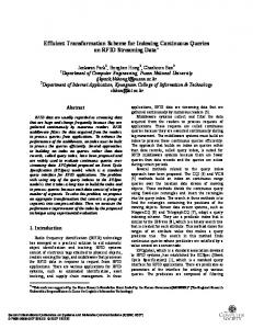
Fig. 6. The transposition conductors including the tube-type copper conductor and stair-type copper conductor: (a) phase a to phase c, (b) phase b to phase a, and (c) phase c to phase b.
cable for insulation and a superconducting joint to minimize loss in the joint area. Fig. 5.
The support structure for insulation and cryogen flow.
III. D ESIGN OF A T RANSPOSITION -BASED C ONNECTION S CHEME A transposition-based connection scheme for the tri-axial HTS power cable is suggested. To lay the cable on a real power grid, several joint connections are required since the maximum unit length of the cable is decided for its transportation using a cable reel or cable drum. As mentioned above, the tri-axial HTS power cable has an inherent imbalance impedance between the three phases. The imbalance impedance can cause some problems on the operation of the power grid, such as a difference in the voltage drop of the distribution line and the current of each phase. Therefore, to apply the cable to the distribution line of a power grid, a transposition-based joint connection is needed. A. Concept of the Connection Scheme The joint connection of the cable is based on a transposition between the three phases. Through basically the two joint connections, the inductances of each phase in the cable become equal to the sum of L1 , L2 , and L3 , as shown in Fig. 4. The capacitances of the cable also become equal. Thus, impedances of each phase in the cable are well-balanced in the overall length of the cable. The joint connection scheme of the cable is achieved through sectionalization of the cross-section of the
B. Design of the Transposition-Based Joint Box The transposition-based connection scheme is realized through a support structure with an insulation function for phases and a passage function for cryogen, as well as transposition conductors with a connection function between a phase on one of the cable and a phase on another. The support structure has three walled-off areas to insulate the three phases and a hole in the center to pass cryogen as shown in Fig. 5. The transposition conductors are designed with an emphasis on the minimum joint loss through the superconducting connection. The transposition conductors consist of tube-type copper blocks and a stair-type copper block for the connection of one phase to another phase; these copper blocks are assembled as one unit as shown in Fig. 6. The dimensions of transposition conductor are shown in Fig. 7. The superconducting connection for transposition between the cables is achieved using an inclined terminal shape and a stair shape. The same amount of superconducting wires for each phase is located on the stair-type copper block to keep the current capacity of each phase. The superconducting wires on each phase of the cable and the other wires on the stairtype copper block are connected without copper junction in the inclined terminal of the transposition conductor. The support structure is assembled with the transposition conductors as a framework for the transposition-based connection of the cable.
5400704
IEEE TRANSACTIONS ON APPLIED SUPERCONDUCTIVITY, VOL. 25, NO. 3, JUNE 2015
IV. C ONCLUSION A 22.9 kV/50 MVA distribution class tri-axial HTS power cable and joint box, including a transposition-based connection scheme, were designed in this paper. Emphasis was placed on impedance balancing of the cable for grid application with loss minimization. The transposition-based joint box is composed of a support structure with three walled-off areas and transposition conductors including a superconducting connection. The impedance balancing of the cable is accomplished using two joint boxes in overall length of the cable section which is divided into three parts. Through the design results, the joint box will be fabricated and tested to confirm its feasibility in the near future. The design of the joint box will be reflected in a tri-axial HTS power cable system to apply the cable to a power grid with stable operation. Fig. 7. The dimensions of transposition conductors: (a) phase a to phase c, (b) phase b to phase a, (c) phase c to phase b.
Fig. 8. The assembly diagram of a transposition-based joint box.
Through assembly of these parts, the joint box, including the transposition-based connection scheme for the cable, is configured, as shown in Fig. 8.
R EFERENCES [1] J. Cho et al., “Development of a single-phase 30 m HTS power cable,” Cryogenics, vol. 46, pp. 333–337, May 2006. [2] K. Shimoyama, N. Ozcivan, S. Soeda, N. Hu, and Y. Onoe, “Experimental results of tri-axial HTS cable,” Cryogenics, vol. 49, pp. 398–401, Aug. 2009. [3] M. A. Young et al., “An investigation of the current distribution in the triaxial cable and its operational impacts on a power system,” IEEE Trans. Appl. Supercond., vol. 15, no. 2, pp. 1751–1754, Jun. 2005. [4] A. N. Ozcivan et al., “AC loss of a multi-layer per phase tri-axial HTS cable with balanced current distribution,” J. Supercond. Novel Magn., vol. 24, no. 1/2, pp. 975–980, Jan. 2011. [5] S. Kruger Olsen et al., “Loss and inductance investigations in a 4-layer superconducting prototype cable conductor,” IEEE Trans. Appl. Supercond., vol. 9, no. 2, pp. 833–836, Jun. 1999. [6] T. Hamajima et al., “Balanced three-phase distribution experiment of a triaxial HTS cable,” Electron. Commun. Jpn., vol. 94, pp. 51–58, Jan. 2011. [7] D. Politano, M. Sjosrom, G. Schnyder, and J. Rhyner, “Technical and economical assessment of HTS cables,” IEEE Trans. Appl. Supercond., vol. 11, no. 1, pp. 2477–2480, Mar. 2001. [8] S. K. Ha, “Development of an impedance matching program for balancing the current distribution in a tri-axial HTS power cable,” J. Supercond. Novel Magn., vol. 26, no. 4, pp. 759–762, Apr. 2013. [9] H. J. Kim et al., “Insulation studies and experimental results for high Tc superconducting power cable,” IEEE Trans. Appl. Supercond., vol. 15, pp. 1727–1730, Jun. 2005.