DYNAMIC SIMULATION OF POSSIBLE HEAT MANAGEMENT SOLUTIONS FOR ADIABATIC COMPRESSED AIR ENERGY STORAGE
Daniel Wolf*, Sascha Berthold, Christian Dötsch Fraunhofer Institute for Environmental, Safety and Energy Technology UMSICHT Osterfelder Straße 3, 46047 Oberhausen, Germany *phone: +49 208 8598 1422, fax: +49 208 8598 1423
[email protected] José Ureña Lopez, Timur Erkan, Roland Span Chair of Thermodynamics – Ruhr-University Bochum Universitätsstr. 150, 44780 Bochum, Germany
ABSTRACT Adiabatic Compressed Air Energy Storage (A-CAES) represents a zero emission electrical storage technology together with acceptably high cycle efficiency. Therefore the application of internal heat storage becomes necessary. One main characteristic of such A-CAES is that the heat generated during compression exceeds the amount of usable heat for the expansion process afterwards. In real life cycling mode this could lead to a heat storage overload. For heat storage management four possible solutions are proposed and discussed quantitatively. A dynamic model of the whole A-CAES process is under development with the focus on the stratified high-temperature heat storage. After an introduction to basic mechanisms relevant for the understanding of heat management in an A-CAES context, a brief explanation of model structure is given. 1. Motivation By now compressed air energy storage (CAES) is applied only in the multi megawatt range for electricity storage [1][2]. Accepting a slight decrease in efficiency CAES is also applicable with smaller plant size (1-30 MW) gaining site and cycling flexibility which are important requirements for a further integration of intermittent renewable energies such as wind energy and photovoltaics. The efficiency drawback of such smaller CAES plants could be compensated by the application of a thermal storage system (TES) transferring the heat generated during compression to the expansion process. One main characteristic of an adiabatic CAES (A-CAES) is that the heat generated in the compression process exceeds the amount of usable heat for the expansion process afterwards. Within several charging and discharging cycles the surplus heat would lead to an overload of the TES. As a consequence the air cannot be cooled down enough in the TES, in an intercooled process higher compressor stages suffer greater thermal stresses, the overall efficiency of the system decreases and the storage temperature inside the compressed air tank reaches safety relevant values. Therefore this effect demands a suitable heat management concept for CAES systems. The present paper analyses the basic principles leading to this excess heat. Possible solutions to control the heat balance of the TES are discussed. An outlook to a new A-CAES design method based on dynamic simulation is given. Effstock 2009
1
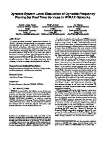
2. Thermal load balance of an adiabatic CAES How adiabatic CAES works Figure 1 shows a simplified process scheme of an adiabatic CAES process. During compression mode the heat of the hot compressed air is stored in a TES before the compressed air enters the pressurised tank. In expansion mode stored air is released from the tank and heated up again by flowing through the TES. Finally the hot air expands in a rotating machine und drives the generator.
M
Comp
Exp
G
Thermal Energy Storage (TES)
Compressed Air Storage
Figure 1: Simplified process scheme of an adiabatic CAES The term excess heat is to be interpreted as the balance between generated heat during compression und usable heat for expansion. Therefore it is assumed that all the compression heat could be stored in the TES under consideration of a temperature spread necessary for heat transfer from the air to the TES and vice versa. The main driving forces for the excess heat phenomenon can be explained by the two following principle effects: n
non-isentropic compression and expansion
n
humidity of ambient air
These effects need to be explained for further understanding. Thermodynamic Background Assuming 100 bar as maximal storage pressure an adiabatic single stage compression of dry ambient air (20°C) would lead to outlet temperatures of about 800 - 900°C (see Figure 2). Omitting such high temperatures a multistage compression with re-cooling becomes inevitable. In case of adiabatic CAES re-cooling mainly takes place directly within the TES. Furthermore Figure 2 indicates an ideal compression with no friction or real gas effects (light grey line) together with a real non isentropic compression with an isentropic efficiency of 0.81 (dark grey line). It can be seen that especially at lower pressure ratios (2-10) outlet temperature of the real-case is much higher (up to 23%) compared to the ideal-case than towards higher compression ratios (down to 10%) mainly due to real gas effects. In Figure 2 this is indicated by the dotted line and calculated by 100* ΔTreal-ideal / [Toutlet-Tinlet]. To reach a tolerable max. temperature of up to 500°C a multi stage compression with moderate pressure ratios (4-6) becomes necessary. The temperature rise from ideal to real compression becomes significant especially in that range. Now, why should this be of importance for the understanding of the excess heat phenomenon?
Effstock 2009
2
Temperature [°C]
Relaive rise in temperature 25,0%
1200
1000
20,0%
800 15,0% 600 10,0% 400 Temperature; real; ηs,V = 0,81 5,0%
Temperature; ideal; κ=1,4
200
Relative rise in temperature real to ideal relating to temperature rise during compression 0 0
25
50
75
100 125 Pressure [bar]
150
175
0,0% 200
Figure 2: Temperature over outlet pressure of an adiabatic compression of dry air (left axis) and relative rise in temperature real compared to ideal compression (right axis). Non-isentropic compression and expansion in A-CAES The answer to that question can be demonstrated obviously in a T,s-Diagram (see Figure 3). Therein a real non-isentropic compression (1-2) comparable to the dark grey line in Figure 2 is indicated. After the compression the diagram shows a real non-isentropic expansion (2-3). One can see that due to frictional losses, which also can be interpreted as a rise in specific entropy, the exhaust temperature T3 is higher than the suction temperature T1. Poor isentropic efficiencies of the rotating equipment, both for compression and expansion sustain this effect by raising temperatures T2 and T3.
T
p2 2
TComp
p1
TExp 3 1
s Figure 3: T,s Diagram of an non-isentropic compression and expansion
Effstock 2009
3
In current diabatic CAES processes the remaining exhaust heat on the temperature level T3 is used via a recuperator to preheat the suction air [3]. In the diabatic case, without thermal storage this results in a desired increase of efficiency. With thermal storage between compression and expansion this would lead in addition to excess heat inside the TES. Due to this effect heat recuperation should be omitted in case of adiabatic CAES. Doing so, frictional losses during compression and expansion lead to higher exhaust temperatures T2 and T3 but do not cause any excess heat in the TES. For the same reason a multistage TES arises similar problems. After the expansion process of the high pressure stage air would enter the low pressure TES on a still elevated temperature level T3 (compare Figure 4) and thus not extract the same amount of heat as charged with during compression mode. As a consequence the load balance of the high pressure TES would be rather unaffected whereas the load balance of the lower pressure stages TES would not be equilibrated and excess heat gets accumulated.
M
Comp LP
Comp HP
TES HP
TES LP
3 G
Exp LP
CAS
2
Exp HP
Figure 4: Simplified process scheme of a 2-stage adiabatic CAES Humidity of ambient air in A-CAES The second effect mentioned before bases on the ability of ambient air to carry a certain amount of vaporised water. Basically, the ability of air to carry water rises with temperature and falls with pressure. When the temperature drops below the dewpoint water starts to condense. Within a CAES process this usually happens in compression mode after the higher pressure stages of the TES or respectively in the final re-cooler when air is cooled down again. The condensed water, also called free water, has to be separated from the air mass flow. Separating the free water, mass flow as well as heat capacity flow of the air to be stored decreases in comparison to the sucked ambient air volume flow. During generation mode almost dry air gets heated up by the TES at a lower specific heat capacity than humid air. As a consequence the amount of extractable heat from the TES during generation mode is smaller than the amount of stored heat during compression mode. Thus excess heat is accumulated in the TES in addition to the excess heat due to the first effect. Figure 5 shows the share of excess heat over relative humidity for different air temperatures for a certain plant layout. For moderate weather conditions the effect of humidity on the TES load balance is relatively small (