Proceedings of the 2001 Winter Simulation Conference .... Binding a function call to the address .... new cell to allow the phone call connection to continue.
Proceedings of the 2001 Winter Simulation Conference B. A. Peters, J. S. Smith, D. J. Medeiros, and M. W. Rohrer, eds.
COMPONENT-ORIENTED SIMULATION ARCHITECTURE: TOWARD INTEROPERABILITY AND INTERCHANGEABILITY Gilbert Chen Boleslaw K. Szymanski Department of Computer Science Rensselaer Polytechnic Institute Troy, NY 12180, U.S.A.
ABSTRACT
simulated. It differs from a simulation in that it is not executable. For instance, an event list usually cannot be found in a simulation model. Since the real component that a simulation model represents may exist in different systems, it is expected that the same simulation model should appear in many simulations. This, unfortunately, is not the case at all. The best that we can achieve today is the interchangeability among simulations built with the same simulator. When facing the problem of simulating a real system, the first thing that the designers consider is selecting a simulator that seems to be best suitable for the particular application. After making a choice, the designers start building simulations according to the standard defined by the simulator. Selection of the simulator is always difficult, and the choice more often depends more on the experience of the system designer than on the features of the simulator. In the worst case, the chosen simulator may be later found unsuitable for the particular application because of some reasons unforeseen at the design stage. Switching the designed system to another simulator usually means all models developed so far have to be rewritten. Our approach tries to address both interoperability and interchangeability in a balance way. This is possible thanks to the component-oriented world view and the simulation component classification discussed briefly in the next section (more detailed discussion of this classification can be found in (Chen and Szymanski 2001)). In Section 3, we introduce CORSA. The design considerations and implementation issues of a prototype are discussed in Section 4 and 5. A PCS network simulation built using the CORSA approach is described in Section 6 which demonstrates the feasibility and advantages of component-based simulations. Finally, the discussion of limitations of our work and plans for future work conclude this paper.
In this paper we investigate two issues at the kernel of simulation reusability: interoperability and interchangeability. Their implications on the simulation technology are discussed. Based on our previous work on simulation component oriented world view and simulation component classification, the Component-ORiented Simulation Architecture (CORSA) is devised to address both issues. The ideas and considerations which motivated us in developing CORSA are discussed. The design and implementation of a prototype is also described briefly. A sequential PCS simulation has been developed using CORSA. This exercise demonstrated several advantages of the component-based approach: flexibility, extensibility as well as reusability. Experimental results show that the component-based approach is only slightly slower than the monolithic approach, whose complexity quickly grows to nearly unsurmountable proportions with the growth of complexity of the simulated system. 1
INTRODUCTION
The importance of interoperability of simulators has been gradually realized and understood. Interoperability enables the system designer to reuse existing simulations, and/or to combine them with new ones to form large and complex simulations which seemed impossible to design even a few years ago. The High Level Architecture (HLA)(Kuhl et al. 1999) is the first extensive effort to attack the problem of simulation interoperability. The publishing and subscription scheme allows all objects in an HLA-compliant simulation to be reused by other simulations. However, simulation interoperability only represents one level of reuse. Another level of reusability has often been ignored: the interchangeability of simulation models. A simulation model is a part of a simulation. It describes the dynamic behavior of a component of the system being
495
Chen and Szymanski 2
a time advance via a special entity called a timer. Timers provide a mechanism for the component to schedule and receive events. To schedule an event, a timer is set with a specified value representing a future simulation time at which the event will occur. As soon as the simulation time reaches the value preset by the timer, the corresponding component will be activated and will process the event that it has scheduled. Type III components maintain their own simulation clock themselves. They do not have any timers. Instead, they contain a clock, which indicates the simulation time throughout the execution. These components can receive a message only if such a message will not cause causality errors. The easiest way to guarantee it is to accept only those received messages that have timestamp larger than the value of the simulation clock.
COMPONENT-BASED SIMULATION
Component-based approach is a natural and intuitive approach to the development of large-scale simulations. To help us understand its usefulness in building simulations, it is necessary to turn to traditional simulation modeling methodologies at first. 2.1 Simulation World Views Traditional simulation world views, such as Event Scheduling, Activity Scanning, and Process Interaction (Cota and Sargent 1992), do not emphasize the composability of simulation models. When adopting these world views, the designers tend to model the real system as a whole, which inevitably limits the reusability of the simulation model. The logical process paradigm (Fujimoto 1990), arising from the necessity of simulated system partitioning in PDES (Parallel Discrete Event Simulation), achieves a certain degree of composability. However, this paradigm does not separate the development of logical processes from the simulation into which they are integrated, thus preventing them from being reusable in other simulations. We proposed a component-oriented world view in which a simulation is composed of a number of components. Two major differences distinguish a component from a logical process. First, components communicate with each other through input/output ports instead of events. Second, a configuration phase must be performed for components before the execution or even compilation of the system. In configuration phase, component parameters are assigned values and component ports are interconnected. The configuration phase, together with the indirect communication via input/output ports, make the component development completely independent of the simulation context.
Simulation Engine
Type II
Type II
Timer
Type I
Type II
Input/Output Port
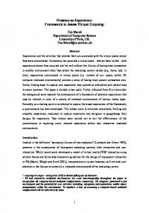
Figure 1: Simulation Engine for Type I and Type II Components Type I and Type II components can be coupled together by a simulation engine, as illustrated in Figure 1. The simulation engine is responsible for parameterization and interconnection of components. During the interconnection, it sets up channels that directly connect matched ports. The simulation engine must also keep track of all activities on timers. When a timer is scheduled to be active in a future simulation time, the simulation engine inserts a corresponding event into a priority queue. It repeatedly removes the event with the smallest timestamp from the priority queue and then activates the corresponding timer by invoking the event handler of the component to which the timer belongs.
2.2 Component Classification Components are classified into three types with respect to the way they handle the time semantics: timeless, timedependent and time-independent, called Type I, Type II and Type III respectively (Chen and Szymanski 2001). A Type I component does not have the notion of simulation time. It is passive in the sense that it never generates messages without first receiving a message. A component, when processing a messages received from other components, may generate a new message that has the same timestamp as the incoming message that triggered it. Yet, the component itself is not aware of the time semantics. Neither does it know whether it is running as part of a simulation program or part of an ordinary program. For this reason, the timeless component is said to be time-unaware. Type II components are time-aware. They cannot advance the simulation time themselves but they can request
2.3 Implications of Classification The classification of simulation components into three types clarifies the role of the simulation developers. A simulation program can be divided into two parts: one part models the behavior of the real system and the other simply makes the model executable. In this sense, the Type III components have nothing to do with modeling of the real system, since they are only concerned with the underlying implementation issues. Hence, these components should be hidden from the
496
Chen and Szymanski 3
model builders who usually have no specialized knowledge of the simulation technology. On the contrary, the Type I and Type II components include both the code that represents the real system and the code that allows components to execute. The latter is the sole responsibility of the simulator builders but should be transparent to the model builders. The classification fits into parallel computation well. In practice, a simulation model of a real system may contain an excessive amount of parallelism. However, direct mapping into a parallel program is unnecessary and often inefficient, because the optimal granularity of runtime parallelism is only determined by the number of processors available in a simulation run. It is well known that two parallel programs running on one processor always require context switching, which incurs signification overhead. The classification allows us to avoid this problem by mandating that all Type I and Type II components contained within a processor execute sequentially. Only one component can be active at any one time. A Type I or Type II component is immediately suspended after writing to an output port. The input port connected to this output port is then activated and the component where the input port resides starts to process the arriving message in this input port. If there are multiple input ports connected to the output port, all connected input ports should be activated in an implementation dependent order. The component that initiated the communication resumes only after all components connected by the output port have finished execution. When a component processes a message arriving at an input port, it may write to one or more output ports and transfer execution to the successive components. A close examination reveals that components impose different requirements on the timestamp of the simulation time. Type I components require copyable timestamps, because they must copy the timestamp of a message arriving in an input port to outgoing messages which can only occur at the simulation time of the received message. Type II components require addable timestamps, because when they write a delay to a timer, they implicitly schedule an event whose timestamp is equal to the current simulation time plus the specified delay. Type III components naturally ask for comparable timestamp for the purpose of selecting the smallest timestamp. In practice, the simulation time is usually implemented using floating-point numbers, which possess all three above properties. These properties are the most common requirement of each type, but not necessarily all the required properties. For example, a component modeling a time-variant system may require the property of being readable, which is different from any of the properties mentioned above.
SIMULATION PLATFORM
Historically, operating systems, the platforms on which traditional simulations are conducted, are all componentoriented. A complete operating system consists of many programs, which can be viewed as components providing a wide variety of functionalities. Users can install programs that they want and remove those they do not. An operating system often allows a simple but efficient form of interoperability between programs. A program may invoke other programs, in the form of shared library (Levine 2000), or even in a more sophisticated model like Microsoft COM (Armstrong 2000). Model level reuse is made possible by efforts like STL (Austern 1998). However, current operating systems do not provide sufficient support for the configuration phase required by the component-oriented world view. For example, although it is possible to parameterize a program by passing command line arguments, the parameters represented by these arguments are program-specific, thus parameterization cannot be done in a unified way. Binding a function call to the address of the function resembles linking an output port with an input port, but multiple connections to one port cannot be defined. For this reason, we propose a simulation platform, called CORSA (Component-ORiented Simulation Architecture), based on the component-oriented world view. The component classification described in the previous section plays an important role in the design and implementation of this simulation platform. CORSA defines a component development standard which serves as a contract between the developers of simulation engines and the developers of components. It enables a scenario in which once a CORSA-compliant simulation engine has been designed to link a certain type of components, it will be able to accept any components that belong to this type. The term ‘simulator’ will be synonymous with the term ‘simulation engine’. Non-compliant simulators not designed within the CORSA model can be wrapped and treated as Type III components but they will not be able to use standard components. Component Standard Non−standard Simulators Repository Simulators 000000000000000 111111111111111 Simulation API 000000000000000 111111111111111 000000000000000 111111111111111 Simulation Platform Operating System
Figure 2: The CORSA Simulation Platform Figure 2 shows the architecture of the CORSA simulation platform. Built on top of an operating system, it provides
497
Chen and Szymanski 4.2 Component Interface Description Language
supports for standard simulators. Non-standard simulators are wrapped with interfaces with allow them to be plugged into the simulation platform. The simulation platform also contains a component repository to facilitate management of the components. The key part of the development will be a simulation API (Application Programming Interface). Besides common functionalities required by simulation programming, like random number generators, priority queues, message passing, etc., it must allow the simulators to access the information of components and their input/output ports, timers, and clocks. 4
A CIDL (Component Interface Description Language) is defined to describe the interface of components. A CIDL file describes the name and type of every port, timer or clock in a component. This way of describing interface is similar to the CORBA IDL. However, CORBA IDL cannot be directly used to describe CORSA components, because the primitive elements are different. Moreover, CORBA only deal with Type I component according to our classification. Examples of CIDL interfaces can be found in Section 6. We have also implemented a CIDL compiler to facilitate the development of components. The CIDL compiler translates a CIDL interface into a skeleton from which the component implementation can be derived. Currently only CIDL to C++ mapping has been implemented.
DESIGN OF A CORSA PROTOYTYPE
We have developed a prototype of the proposed simulation platform. The main purpose of this prototype is to demonstrate that both interoperability and interchangeability are achievable at the same time. One important part that is missing is the simulation API. Design of this API is by no means a trivial task: it must be based on the knowledge and experience gained from continuous efforts in the component-based simulation.
5
IMPLEMENTATION ISSUES
In this section, we introduce the class hierarchy of components used in the simulation platform prototype. The use of function objects is also described.
4.1 Two Levels of Reuse
5.1 Class Hierarchy of Components
As mentioned in the first section, the interoperability enables simulation-level reuse and the interchangeability enables model-level reuse. These two kinds of reuses can be achieved in two ways, depending on the form and class of components involved. Type III components are in the form of either binary libraries or source code, but Type I and Type II components exist only as source code modules. Therefore, two types of simulation engines are possible: one type accepts binary libraries and the other accepts source code modules. Type I or Type II components can be compiled into binary libraries. Such compilation is useful when a Type I or Type II component is to be linked to Type III binary components. For example, a delay between two Type III components can be modeled as a component of Type II, therefore a delay model can be retrieved from the component repository and then compiled into a binary component. Binary components are actually shared libraries. This is a natural choice because it allows the simulation platform to load components during the run-time. A predefined component creation function is required to be implemented by every binary component. It will create a component instance upon invocation after the component library is loaded into the computer memory for execution. An existing simulation can be easily wrapped with a few necessary functions to become a shared library.
Figure 3 shows the class hierarchy of the prototype of the CORSA simulation platform. A Component class is defined as the base class of all types. It contains public member functions for parameterization and interconnection required by the component standard. In addition, it defines a SimTime() function which returns the current simulation time. Platform
Component
...
SimTime() ...
TypeI
TypeII
TypeIII
SimEng
SetTimer() CancelTimer()
Run() double m_clock
...
CostSimEng ...
SeqSimEng ...
Figure 3: The Class Hierarchy for the CORSA Simulation Platform The Type I component class is a trivial derived class of the Component class. It does not introduce any new member functions. The Type II component class defines two new member functions: SetTimer() and CancelTimer(). The SetTimer() function sets a timer with a specified delay. As soon as
498
Chen and Szymanski the simulation time expired since the instance in which the timer was set is equal to the delay, this timer will become active. CancelTimer() simply disables a timer. Type III components are provided with a new member function Run() because they can manage the simulation clock themselves so that they are runnable. The member variable m_clock contains the value of the current simulation time. An abstract SimEng class is also defined in the class hierarchy. It serves as the interface for all simulation engine classes, i. e., every simulation engine class should implement the pure virtual functions declared in the SimEng class. Because a simulation engine is also a component, either of Type II or of Type III, a simulation engine class is derived using multiple-inheritance. A simulation engine that is of Type II permits hierarchical modeling methodology. We have developed two Type III sequential simulation engines: SeqSimEng accepts binary components and CostSimEng accepts source code components.
function objects, type checking of two arbitrary ports is impossible because two port may reside in two shared libraries compiled separately, thus the compiler cannot detect the type mismatching. Using function objects, the pointer to a function object is first upcast to a pointer to a Functor object. This pointer is then passed to the port in another shared library. To decode this pointer to its original type, the C++ operator dynamic_cast is used. Decoding the pointer to any other type will result in a null pointer, which can be detected by the component during the run time. 6
A PCS (Personal Communication Service) network contains a geographically distributed radio ports (Carothers et al. 1994; Boukerche et al. 1999). The users in the coverage area (or cell) of a port can use the channels assigned to that port. When a user moves from one cell to another during a phone call, a hand-off is said to occur. In such a case, the PCS network attempts to allocate a radio channel in the new cell to allow the phone call connection to continue. The PCS network simulation involves two object types: cell and portable. The cell allocates the radio channels to the portables and detects portables that have moved out of its coverage area. The portables simulate call activities and movements.
5.2 Function Object Function object (also called Functor) is widely used in the implementations of the ports and timers. Conceptually, it is a generalization of the function pointer (Austern 1998). In C++, function objects are constructed using operator overloading. Figure 4 shows the class hierarchy of the function objects.
6.1 Two Reusable Components In the PCS simulation experiments, we adopt a partition scheme different from those used for parallel simulation (Carothers et al. 1994; Boukerche et al. 1999). A cell component simulates all the cells, that is, it processes all the requests of channel allocation and release. A portable component simulates all the portables. This partition scheme is difficult to be applied to parallel simulation, but is well-suited for the purpose of demonstrating the advantages of the component-based simulation and of comparing the overhead of inter-component communication. The interface of the cell component, which is a Type I component, is given below. The parameters width and height define the number of cells in the horizontal and vertical direction, respectively. The parameter channels_per_cell specifies the number of available channels that each cell initially possesses. The input port GetChannel is activated when a portable needs to make a phone call. The cell component then checks if there is any channel currently available in the cell specified by the argument index. The availability is returned by the argument available that is passed by reference. The input port ReleaseChannel is activated when a portable releases a channel that it has been using.
Functor virtual ~Functor()
TriggerFunctor
UnaryFunctor
BinaryFunctor
TernaryFunctor
operator ()()
operator()(T t)
operator()(T1 t1, T2 t2)
operator()(T1 t1, T2 t2, T3 t3)
TriggerMFunctor
UnaryMFunctor
BinaryMFunctor
TernaryMFunctor
operator ()()
operator()(T t)
operator()(T1 t1, T2 t2)
operator()(T1 t1, T2 t2, T3 t3)
PCS SIMULATION USING CORSA
Figure 4: Functor Objects Used in the Implementation First, a base Functor class is defined. Next, a set of function object classes are derived, each of which takes different numbers of arguments. Finally, a set of member function object classes are derived from the corresponding non-member function object classes. The advantage of using function objects is that type checking for ports becomes possible. For instance, when we connect an input port with an output port we need to make sure that they are matched. That means, both of them should take the same number of argument, and arguments in the same position should be of the same type. Without
499
Chen and Szymanski 6.2 Experimental Results
component cell { param int width; param int height; param int channels_per_cell; inport GetChannel(int index, bool& available); inport ReleaseChannel(int index); }
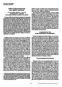
A series of experiments have been conducted to test the performance of the component-based approach. Figure 5 shows the simulation speeds in these experiments. Two simulation engines mentioned earlier were tested. For each simulation engine, two experiments were performed. First, the simulation was constructed using one cell component and one portable component. Next, one cell component and two portable components were used, with each portable component simulating half of the workload. The number of event processed in one simulation run remains the same.
The portable component is a Type II component. The parameter portables_per_cell states the number of portables in each cell at the beginning of the simulation. The parameters next_call_mean and next_move_mean define the average time between two consecutive calls, and two consecutive moves, respectively. The parameter call_time_mean indicates the average duration time of a call. All time durations are drawn from exponential distributions. Two output ports, GetChannel and ReleaseChannel, are used to request and release channels. The portable component also contains a timer, which is set with the smallest timestamp of all future events occurring to this portable component. When this timer is activated, the portable component knows that it is its turn to process the next event.
600000
Event Processing Rate (events/sec)
Monolithic CostSimEng(2 components) CostSimEng(3 components) SeqSimEng(2 components) SeqSimEng(3 components) 550000
500000
450000
400000 8x8
Component portable { param int width param int height; param int portables_per_cell; param double next_call_mean; param double next_move_mean; param double call_time_mean; outport GetChannel(int index, bool& available); outport ReleaseChannel(int index); timer next; }
12x12
16x16
Number of cells
Figure 5: Comparison of Simulation Efficiency It is no surprise that the monolithic approach is the fastest. In general, the component-based approach is approximately 20% slower than the monolithic approach for the PCS simulation. It is worth mentioning that the PCS model is fine-grained: the amount of computation required to process each event is relatively small. Hence, the overhead of inter-component communication becomes more significant. For coarse-granularity models, the inter-component communication would impact the overhead and overall performance to a lesser degree. We can also see that the simulation engine CostSimSim is faster than SeqSimEng. This is understandable because the former integrates source code components so it is more tightly-coupled. Dividing the workload into two portable components only slightly slows down the execution speed.
There are two advantages to modeling PCS networks in that way. First, this model separates the cell component from the portable component, thus making it fairly easy to modify the cell component when a different channel allocation policy is adopted. Second, the simulation constructed in this way is fully extensible. For example, some of the portables may be carried by moving vehicles, and we want to simulate the behavior of vehicles as well. We can create a new vehicle component, and link it with the cell component. The resulting three components (cell, portable, and vehicle) will work correctly with each other without any additional considerations for their synchronization!
7
CONCLUSION
The Component-ORiented Simulation Architecture, CORSA, is presented in this paper. It supports both interoperability and interchangeability. We have conducted a PCS simulation using CORSA and defined two components run by a simulation engine. The same two components that simulate cells and portables can be used in two different simulation engines. Experimental results
500
Chen and Szymanski BOLESLAW K. SZYMANSKI is a Professor of Computer Science. He has been at Rensselaer since 1985. In the past he was also affiliated with the University of Pennsylvania, Aberdeen University (U.K.) and Warsaw Polytechnic (Poland). Dr. Szymanski received Ph.D. in Computer Science from National Academy of Sciences in Poland in 1975. He is an IEEE Fellow, ACM National Lecturer, Editor-in-Chief of Scientific Programming. He has edited and contributed chapters to several books and authored over 150 research papers in journals and conference proceedings. His research has been supported by NSF, DARPA, ONR, ARO, NASA and industry. His current research focuses on pro-active network management, distributed and parallel computing and computational models of evolution, epidemics and biomedical systems. He has been also involved in econometric modeling, algorithm design and information retrieval.
show that the component-based approach incurs insignificant inter-component communication overhead, while supporting reusability, composability and extensibility. However, the prototype that we presented here is far from being a full-fledged simulation platform that we have envisioned. The design of a key part of the simulation platform, the simulation API, has been omitted in this prototype. The component development standard, which serves as a contract between the simulator developers and the model builders, is still informal and subject to future changes. Another limitation of our work is that the componentbased approach is only tested on sequential simulations. As mentioned earlier, the component classification fits into parallel computation well. Therefore, its real power will be fully exploited in parallel discrete event simulations. The emphasis on interchangeability will allow parallel simulators based on different algorithms to reuse the same components. A comprehensive comparison of existing parallel algorithms on a wide variety of applications will hence become feasible. REFERENCES Armstrong, T. 2000. ATL developer’s guide. Second ed. M&T Books. Austern, M. H. 1998. Generic programming and the STL. Addion Wesley Longman. Boukerche, A. et al. 1999. Exploiting model independence for parallel PCS network simulation. In Proceedings of the 13th Workshop on Parallel and Distributed Simulation, 166–172. Carothers, C. D. et al. 1994. Distribued simulation of largescale PCS networks. In Proceedings of the Second International Workshop on Modeling, Analysis, and Simulation of Computer and Telecommunication Systems, 2–6. Chen, G., and B. K. Szymanski. 2001. Componentbased simulation. In 2001 European Simulation MultiConference, 68–75. Cota, B. A., and R. G. Sargent. 1992, April. A modification of the process interaction world view. ACM Transactions on Modeling and Computer Simulation:109–129. Fujimoto, R. M. 1990, October. Parallel discrete event simulation. Communication of the ACM:30–53. Kuhl, F. et al. 1999. Creating computer simulation systems: An introduction to the high leverl architecture. Prentice Hall. Levine, J. R. 2000. Linkers and loaders. Morgan Kaufmann. AUTHOR BIOGRAPHIES GILBERT CHEN is a Ph.D. candidate in Computer Science department at Rensselaer Polytechnic Institute. He received BS and MS degrees in Electrical Engineering from Tsinghua University (P.R.China) in 1995 and 1998 respectively.
501