organization and the data memory hierarchy take portions of chip area and .... tion memory hierarchy for long instruction word processors. In this architecture, a ...
2010 International Workshop on Innovative Architecture for Future Generation High-Performance Processors and Systems
Energy Efficiency using Loop Buffer based Instruction Memory Organizations A. Artes
∗† ,
F. Duarte ∗ , M. Ashouei ∗ , J. Huisken ∗ , J. L. Ayala † , D. Atienza
‡†
and F. Catthoor
§
∗ Holst
Centre / imec Eindhoven (The Netherlands) {antonio.artes, filipa.duarte, maryam.ashouei, jos.huisken}@imec-nl.nl † Facultad
de Informatica Universidad Complutense de Madrid (Spain) {a.artes, jayala}@fdi.ucm.es ‡ EPFL
Laussane (Switzerland) {david.atienza}@epfl.ch § imec
Leuven (Belgium) {catthoor}@imec.be Abstract—Energy consumption in embedded systems is strongly dominated by instruction memory organizations. Based on this, any architectural enhancement introduced in this component will produce a significant reduction of the total energy budget of the system. Loop buffering is an effective scheme to reduce the energy consumption of the instruction memory organization. In this paper, a novel classification of architectural enhancements based on the use of loop buffer concept is presented. Using this classification, an energy design space exploration is performed to show the impact in the energy consumption on different application scenarios. From gate-level simulations, the energy analysis demonstrates that the instruction level paralellism of the system brings not only improvements in performance, but also improvements in the energy consumption of the system. The increase in instruction level paralellism makes easy the adaptation of the sizes of the loop buffers to the sizes of the loops that form the application, because gives more freedom to combine the execution of the loops that form the application.
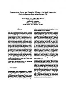
Fig. 1. Power consumption per access in 16-bit instruction word commercial 90nm SRAMs.
execution time is spent in small segments of the application code. Reference [4] presents a study on the loop behavior of embedded applications. This study demonstrates that 77% of the total execution time of an application is spent in loops of 32 instructions or less. Using loop buffering, it is possible to store these small segments of the application code in memories that are smaller than the program memories that are normally used. As shown in Figure 1, these small memories have less energy per access, leading to reduce the total energy consumption of the instruction fetch logic significantly. In this paper, an energy design space exploration of the loop buffer concept is presented. Our analysis introduces a novel architectural classification based on three scenarios where all loop based architectures can fall in. The characterization of the mentioned architectures, the demonstration of this classification into the existing state-of-the-art, and the study of the energy impact of each scenario are performed along
I. I NTRODUCTION The ”Memory Wall” is a well known problem in computer systems. It is based on the growing disparity between the rate of improvement in microprocessor speed and the rate of improvement in off-chip memory speed. This problem becomes even worse in embedded systems, where designers do not only need to consider the performance, but also the energy consumption. In an embedded system, the instruction memory organization and the data memory hierarchy take portions of chip area and energy consumption that are not negligible. Several works like [1], [2] and [3] demonstrate that memories now account for nearly 50% − 70% of the total energy budget of the instruction-set processor platform. Loop buffering is an effective scheme to reduce energy consumption in instruction memory organizations. In signal and image processing applications, a significant amount of 978-0-7695-4396-3/10 $26.00 © 2010 IEEE DOI 10.1109/IWIA.2010.10
59
this paper. Besides, a real-life embedded application is used as a case study to present the energy reduction that can be achieved using instruction memory organizations based on the loop buffer concept. To evaluate the energy impact, post-layout simulations are used to have an accurate estimation of parasitics and switching activity. The evaluation is performed using TSMC 90nm Low Power library and commercial memories. The rest of the paper is organized as follows. Section II presents the related work classification where all loop based architectures can fall in. Section III describes the experimental framework used in the energy design space exploration, whereas Section IV is focused on the description of the benchmarks used in the evaluation of the architectural models proposed in Section II. Section V shows and analyzes the results obtained from the evaluation of the experimental framework. Finally, the conclusions are briefly summarized in Section VI.
branch instructions. This architectural enhancement has neither an address tag store nor valid bit associated with each loop cache entry. Johnson Kin et al. [9] evaluate the Filter Cache. This enhancement is an unusually small first-level cache that sacrifices a portion of performance in order to save energy. The program memory is only required when a miss occurs in the Filter Cache, otherwise it remains in standby mode. Based on this special loop buffer, K. Vivekanandarajah et al. [10] present an architectural enhancement that detects the opportunity to use the Filter Cache, and enables or disables it dynamically. Also, Weiyu Tang et al. [11] introduce a Decoder Filter Cache in the instruction memory organization in order to reduce the use of the instruction fetch and decode logic by providing directly decoded instructions to the processor. On the other hand, Nikolaos Bellas et al. [12] propose a scheme, where the compiler generates code annotations in order to reduce the possibility of a miss in the loop buffer cache. The drawback of this work is the trade-off between the performance degradation and the power savings, which is created by the selection of the basic blocks. Parallelism is a well known solution in order to increase performance efficiency. Due to the fact that loops form the most important part of an application (as it was mentioned in Section I), loop transformation techniques are applied to exploit parallelism within loops on single-threaded architectures. Centralized resources and global communication make these architectures less energy efficient. In order to reduce these bottlenecks, several solutions that use multiple loop buffers have been proposed in literature. References [14], [15] and [16] are examples of the work done in this field. In our classification, these architectures are classify as multiple loop buffer architectures with shared loop-nest organizations. References [14], [15] and [16] are examples of the work done in this set of architectures. Hongtao et al. [14] present a distributed control-path architecture for DVLIW (Distributed Very Long Instruction Word) processors, that overcomes the scalability problem of VLIW control-paths. The main idea is to distribute the fetch and decode logic in the same way that the register file is distributed in a multi-cluster data-path. On the other hand, Hongtao et al. [15] propose a multi-core architecture that extends traditional multi-core systems in two ways. First, it provides a dual-mode scalar operand network to enable efficient inter-core communication without using the memory. Second, it can organize the cores for execution in either coupled or decoupled mode through the compiler. In coupled mode, the cores execute multiple instructions streams in lockstep to collectively work as a wide-issue VLIW. In decoupled mode, the cores execute independently a set of fine-grain communicating threads extracted by the compiler. These two modes create a trade-off between communication latency and flexibility, that it will be optimum depending on the parallelism that we want to exploit. David Black-Schaffer et al. [16] analyze a set of architectures for efficient delivery of VLIW instructions. A baseline cache implementation is compared to a variety of organizations, where the evaluation includes the
II. R ELATED W ORK During the last decade, researchers have demonstrated that the energy consumption of instruction memory organizations is not negligible. Reference [2] demonstrates, based on a case study, that the contribution of the instruction memory organization is close to 20%−40% of the energy consumption of the whole system. Normally, architectural enhancements that target the reduction of energy consumption make use of loop buffers. In order to study the energy efficiency of the loop buffer concept, an architectural classification based on three scenarios where all loop buffer based instruction memory organizations can be grouped in is presented. The most traditional usage of the loop buffer concept is the first item of this classification. The architectural model that represents it is the central loop buffer architecture for single processor organization. References [5], [6], [7], [8], [9], [10], [11] and [12] are examples of the work done in this set of architectures. N. P. Jouppi [5] analyzes three hardware techniques to improve direct-mapped cache performance: miss caching, victim caching and stream buffers prefetch. Chuanjun Zhang [6] proposes a configurable instruction cache, which can be tailored in size in order to utilize the sets efficiently for a particular application, without any increase in the cache size, associativity, or cache access time. Koji Inoue et al. [7] propose an alternative approach to detect and remove unnecessary tag-checks at run-time. Using execution footprints that are recorded previously in a branch target buffer, it is possible to omit the tag-checks for all instructions contained in a fetched block. If loops can be identified, fetched and decoded only once, Raminder S. Bajwa et al. [8] propose an architectural enhancement that can switch off the fetch and decode logic. The instructions of the loop are decoded and stored locally, from where they are executed. The energy savings come from the reduction of memory accesses as well as the lesser use of the decode logic. In order to avoid any performance degradation, Lea Hwang Lee et al. [13] implement a small instruction buffer based on the definition, detection and utilization of special 60
cost of the memory accesses and the wires which are necessary to distribute the instruction bits. An efficient parallelism is not achieved with the architectures described previously. Using multiple loop buffer architectures with shared loop-nest organizations, loops with different threads of control have to be merged (e.g., using loop fusion) into a single loop with single thread of control. In the case of incompatible loops, the parallelism cannot be efficiently exploited because they require multiple loop controllers. It results in loss of performance. A new set of architectures based on distributed loop controllers solves this problem. In our classification, these architectures are named as distributed loop buffer architectures with incompatible loop-nest organizations. References [17], [18] and [19] are examples of the work done in this set of architectures. Jayapala et al. [17] propose a low energy clustered instruction memory hierarchy for long instruction word processors. In this architecture, a simple profile based algorithm is used in order to perform an optimal synthesis of the clusters for a given application. On the other hand, Praveen Raghavan et al. [18] present a multi-thread distributed instruction memory hierarchy that can support execution of multiple incompatible loops in parallel. In the proposed architecture, each loop buffer has its own local controller, which is responsible for indexing and regulating accesses to its loop buffer. J.I Gomez et al. [19] present a new loop technique that optimizes the memory bandwidth based on the combination of loops with an unconformable header. With this technique, the compiler can then better exploit the available bandwidth and increase the performance of the system. Summarizing, the three scenarios where all loop based architectures can fall in are: • Central loop buffer architectures for single processor organization • Multiple loop buffers architectures with shared loop-nest organization • Distributed loop buffer architectures with incompatible loop-nest organization In the following Sections, we will see how the experimental framework is built based on this architectural classification in order to perform a complete energy design space exploration of the loop buffer concept.
Fig. 2.
Experimental framework.
as starting point for the development of ASIPs (ApplicationSpecific Instruction-set Processors). The processor architecture has the following characteristics: • 16-bit integer arithmetic, bitwise logical, compare and shift instructions. These instructions are executed on a 16-bit ALU and operate on an 8 field register file. • Integer multiplications with 16-bit operands and 32-bit results. • Load and store instructions from and to a 16-bit data memory with an address space of 64k words, using indirect addressing. • Various control instructions such as jumps and subroutine calls and returns. • Support for interrupts and on chip debugging. The processor also supports zero-overhead looping control hardware. This feature allows fast looping over a block of instructions. Therefore, once the loop is set using a special instruction, additional instructions are not need in order to control the loop. The loop is executed a pre-specified number of iterations (known at compile time). The status of this dedicated hardware is stored in the following set of special registers: LS Loop Start address register - It stores the address of the first loop instruction. LE Loop End address register - It stores the address of the last loop instruction. LC Loop Count register - It stores the remaining number of iterations of the loop. LF Loop Flag register - It keeps track of the hardware loop activity. The special instruction, that controls the loops, takes the values of LC and LE as input parameters. This instruction introduces only one delay slot. The experimental framework uses an IO interface in order to provide the capability of receiving and sending data in realtime. This IO interface is implemented directly in the processor architecture. It uses 16-bit FIFOs as data input or output. They
III. E XPERIMENTAL F RAMEWORK As shown in Figure 2, the experimental framework is made up of a data memory hierarchy, an instruction memory organization, a loop buffer, an IO interface, and a processor. The processor is designed and implemented using Target Compiler Technologies [20], and both memories are designed by Virage Logic Corporation tools [21] using TSMC 90nm process. The data memory included in the data memory hierarchy is a memory with a capacity of 16k words/16 bits, and the program memory included in the instruction memory organization is a memory with a capacity of 2k words/16 bits. The general-purpose processor is based on a processor provided by Target Compiler Technologies [20], which is used 61
Fig. 4.
Fig. 3. buffer.
Instruction Memory Organization interface for a single central loop
State-machine.
s1 Transition state between s0 and s2. s2 State where the loop buffer is recording the instructions that the program memory supplies to the processor. s3 Transition state between s2 and s4. s4 State where only the loop buffer is the component that supplies the instructions to the processor. s5 Transition state between s4 and s0. Figure 4 shows the state-machine diagram. The transition states s1, s3 and s5 are necessary in order to give the control of the instruction supply from the program memory to the loop buffer and vice-versa. The transition between s4 and s1 is necessary because the body size of a loop can change in real-time (i.e., in a loop body which if-statements or function calls exist). In order to check in real-time whether the loop body size changes or not, a 1-bit tag is added to each address space. Along this Section, an implementation of the loop buffer concept in a central loop buffer architecture for single processor organizations is presented. In order to mimic multiple loop buffer architectures with shared loop-nest organizations and distributed loop buffer architectures with incompatible loop-nest organizations, the loop buffer architecture has been synthesized with different configurations.
are directly connected to the register file, and new instructions are added to the ISA (Instruction Set Architecture) in order to control them. From Figure 2, it is possible to see that the loop buffer architecture is already included in the instruction memory organization. The details about the interconnections of the processor architecture, program memory, loop buffer architecture and state-machine are included in Figure 3. Although Figure 3 presents a single central loop buffer, our experimental framework is generic enough and can be easily extended to multiple decentralized loop buffer organizations. Section IV demonstrates this. However, for simplicity, a single central loop buffer architecture is used in the next paragraphs to explain the loop buffer operation. In essence, the loop buffer concept operation is as follows. During the first iteration, the instructions are fetched from the program memory to the loop buffer and the processor. The register LF changes its value in the first instruction of the loop body. This change is detected by the state-machine in order to set the proper connections between the different components of the instruction memory organization. The first iteration is when the loop buffer records the instructions that the body of the loop contains. Once the loop is recorded in the loop buffer, for the rest of the loop iterations, the instructions are fetched from the loop buffer instead of the program memory. In the last iteration, the state-machine detects that the value of the register LC is “1” and sets the connections inside of the instruction memory organization, such that subsequent instructions are fetched only from the program memory. During the execution of non-loop parts of the code, instructions are fetched directly from the program memory. Our implementation of the loop buffer is a flip-flop array that can be configured to fit the size and number of the instruction words. The choice of a flip-flop implementation is due to the energy reduction of using flip-flops arrays instead of SRAM memories for small memory sizes [3]. The state-machine is the element that controls the connections inside of the instruction memory organization. It has 6 states in order to control the loop buffer behavior:
IV. E XPERIMENTAL E VALUATION To perform a complete energy design space exploration of the loop buffer concept benchmarks with different patterns are needed. Subsection IV-A describes the synthetic benchmarks that have been developed to show the trends in energy consumption of the architectural models proposed in the classification presented in Section II. Subsection IV-B presents a real-life embedded application mapped on biomedical wireless sensor node which is used to evaluate the energy improvements related with the introduction of the loop buffer concept. Finally, Subsection IV-C explains the simulation methodology used. A. Synthetic Benchmarks The complete energy design space exploration is based on the architectural models presented in Section II. In order to build these architectural models on the experimental framework described in Section III, specific synthetic benchmarks are needed. The required synthetic benchmarks mimic loops that one can find in real-life embedded applications. Every
s0 Initial state. 62
loop that is included in the synthetic benchmarks is characterized based on two parameters: the size of the loop body and the number of loop iterations. The range of loop body sizes of the loops that are included in the synthetic benchmark is based on Reference [4]. This Reference presents a study on the loop behavior of embedded applications that demonstrates that 77% of the execution time of an application is spent in loops with 32 instructions or less. Hence, the size of the loop body of the loops ranges from 1 to 32 instruction words. A limit of 32000 iterations is also imposed based on the same Reference, because it shows that 84% of the execution time is spent in loops with 32000 iterations or less. In order to have precision in the sizes of the loop bodies, the synthetic benchmarks are implemented in assembly code. The instructions and theirs operands that are presented in each loop are randomized. This is different from reality where some correlation is present in these instruction bits, but for the purpose of our loop buffer experiment, these correlations are not that relevant, so they can be ignored here. In order to mimic the energy behavior of the central loop buffer architecture for single processor organizations, a synthetic benchmark with sequential loops is developed. In this synthetic benchmark, the loop body size of the loops ranges between 1 and 32 instruction words, whereas the number of loop iterations ranges between 1 and 32000. The size of the loop buffer of this architecture is fixed to 32 instructions words. With a loop buffer of this size, all the loops that form the synthetic benchmark can be stored without splitting any one of them. In the case of multiple loop buffers architectures with shared loop-nest organizations, the architectural model based on Reference [16] is used. The architecture proposed by this Reference has a loop buffer implementation per each functional unit, where all the loop buffers share the same loop controller. Using the centralized loop buffer architecture presented in Section III), it is possible to imitate the execution of loops in such types of architectures by synthesizing the loop buffer architecture with different sizes. For these architectures, the loops that form the synthetic benchmark has the same variations in the loop body size and number of loop iterations than in the synthetic benchmark presented for the central loop buffer architectures for single processor organizations. For the case of distributed loop buffer architectures with incompatible loop-nest organizations, the synthetic benchmark is based on Reference [18]. In this architecture, not only the loop buffer concept is distributed but also the loop controller. Each loop buffer has its own local loop controller. In order to simulate the execution of loops over this architecture, the same synthetic benchmark like the one described for the multiple loop buffers architectures with shared loop-nest organizations is used in this case. Because we use the same synthetic benchmark, the power figures for both architectures are the same. However, the energy figures are different due to the different instruction level parallelism that each one has. For instance, while multiple loop buffers architectures with shared loop-nest organizations work as single-threaded platforms,
distributed loop buffer architectures with incompatible loopnest organizations can work like multi-threaded platforms allowing the execution of incompatible loops in parallel with minimal hardware overhead. B. HBD algorithm A real-life embedded application mapped on a bio-medical wireless sensor node is used to evaluate the energy improvements related with the introduction of the loop buffer concept in embedded systems. The bio-medical application, used as benchmark in our experimental evaluation, is the HBD (Heart Beat Detection) algorithm which is based on a previous algorithm that Romero et al. [22] developed. This algorithm uses the CWT (Continuous Wavelet Transform) [23] in order to detect heart beats automatically. The algorithm is an optimized C-language version for bio-medical wireless sensor nodes, which does not require pre-filtering and is robust against interfering signals under ambulatory monitoring conditions. The algorithm works with an input frame of 3 seconds, that includes 2 overlaps with consecutive frames of 0.5 seconds each, to avoid the lost of data between frames. The input of this algorithm is an ECG signal from MIT/BIH database [24]. The output is the positions in time-domain of the heart beats included in the input frame. Figure 5 shows the power breakdown related with this algorithm. In this power breakdowns, the components of the processor core are grouped. It is easy to see that the energy consumption in this system is strongly influenced by the consumption of the instruction memory organization.
Fig. 5. Power breakdown for the experimental framework running the HBD algorithm.
After seeing how the instruction memory organization affects the rest of the system, a profiling based on the loops that form the applications was also performed. Figure 6 shows the profile based on the number of cycles per program counter related with the HBD algorithm. From this Figure, and based on the fact that the PC is directly related with the program address space, we can see that there are regions that are more frequently accessed than others. This situation implies the existence of loops. 63
HDL generation tool from Target Compiler Technologies. Because of the HDL generation tool only generates the interfaces of the memories in the design, the data memory hierarchy and the instruction memory organizations had to be added in order to build the whole system. After every component of the system architecture has been built in RTL level, the design is then synthesized using a 90 nm Low Power TSMC library. In this design, a frequency of 100 MHz is fixed and clock gating is used whenever possible. After the synthesis, place and route is performed using Encounter (Cadence tool [25]). After place and route, . it is necessary to generate a VCD (Value Change Dump) file for the time interval of the netlist simulation. These files Fig. 6. Number of cycles per program counter (PC). contain the information of the activity of every net and every component of the whole system. As a final step, the average As we can see from the previous Figures, the HBD algo- power consumption information is extracted with Primetime rithm is a perfect candidate to perform the energy evaluation, (Synopsis tool [26]). For both applications, the time interval because the execution time of the loops represents approx- given to create the VCD file corresponds to the execution time imately 75% of the total execution time of this algorithm, to process an input data frame. and the total energy consumption of the system is strongly V. R ESULTS influenced by the instruction memory organization. The results from the energy design space exploration of the loop buffer architectures based on the classification presented in Section II are presented and analyzed in this Section.
C. Simulation Methodology The simulation methodology used for both applications is described in the following paragraphs.
A. Energy analysis of the synthetic benchmarks The energy analysis of each synthetic benchmark described in Subsection IV-A is presented in the next paragraphs. Each architectural model corresponds with one of the paragraphs. This Figure shows that the energy savings that come from the use of loop buffer architectures are proportional to the number of iterations and the size of the loops that are executed over these architectures. It is possible to see that these energy savings tend to be larger for larger number of iterations. However, when we increase the loop body size, we find a top limit in energy savings due to the maximum of number of instruction words that can be stored in the loop buffer architecture. As shown in Figure 8, the energy savings that we can achieve by introducing a central loop buffer architecture represent a reduction of 68%−74% of the energy consumption that is related with the instruction memory organization. It is necessary to mention that these results are based on the assumption that all the execution time of the application is spent in loops. This is not a realistic case, and therefore the . absolute value of these results cannot be apply in real-life embedded systems. Fig. 7. Simulation Methodology. As was explained in Subsection IV-A, multiple loop buffer The first step in this methodology is to map the application architectures with shared loop-nest organizations and disto the system architecture. With this step, we set how the appli- tributed loop buffer architectures with incompatible loop-nest cation receives the input data and how it generates the output organizations share the same synthetic benchmark. This syndata. The second step is to simulate the mapped application on thetic benchmark mimic the execution of loops in such types the processor in order to check the correct functionality of the of architectures by synthesizing the loop buffer architecture system. For that purpose, an Instruction-Set Simulator (ISS) with different sizes. Besides, the number of iterations and from Target Compiler Technologies is used. Once the correct size of the loops that form this synthetic benchmark suffer functionality of the application is checked, VHDL files of the variations in their values. Table I presents power consumptions processor architecture are automatically generated using the of different loops, when they are executed from loop buffers 64
Fig. 8. Reduction in energy consumption due to the introduction of loop buffer architectures.
Fig. 9.
of the loop buffer architecture. Using the power consumptions of Table I, we can estimate the energy consumption of this instruction memory organization for the system frequency of operation (i.e., 100MHz): ECLB = Elb4LB32 + Elb16LB32 + Elb32LB32 = (3.73 ∗ 10−04 ∗ 4 ∗ 10 ∗ 10−8 ) + (3.73 ∗ 10−04 ∗ 16∗30∗10−8 )+(3.73∗10−04 ∗32∗80∗10−8 ) = 1.15∗10−8 J. Note that in all the calculations, ElbXLBY is the energy that a loop of X instruction words of loop body consumes in a loop buffer with a size of Y instruction words. If the application is executed on a multiple loop buffer architecture with shared loop-nest organization, the first step is to analyze the data dependencies between loops and see whether the loops are not incompatible. In our case study, because we assume that there are not data dependencies, only the loops that have a size of 4 and 32 instruction words can be executed in parallel. The loop that has a size of 16 instruction words is incompatible with both of them, and this architecture do not support execution of multiple incompatible loops in parallel. This scenario can be seen in the case (b) of Figure 9. On one hand, if we use 2 loop buffers with the same size (i.e., 32 instruction words), the energy consumption estimated is: EM LB1 = Elb4LB32 + Elb16LB32 + Elb32LB32 = (3.73 ∗ 10−04 ∗ 4 ∗ 10 ∗ 10−8 ) + (3.73 ∗ 10−04 ∗ 16 ∗ 30 ∗ 10−8 ) + (3.73 ∗ 10−04 ∗ 32 ∗ 80 ∗ 10−8 ) = 1.15 ∗ 10−8 J. On the other hand, if our choice is to adapt the loop buffer size to the loops that are executed over them (i.e., loop buffers of 4 and 32 instruction words), the energy consumption estimated is EM LB2 = Elb4LB4 + Elb16LB32 + Elb32LB32 = (1.02 ∗ 10−04 ∗ 4 ∗ 10 ∗ 10−8 ) + (3.73 ∗ 10−04 ∗ 16 ∗ 30 ∗ 10−8 ) + (3.73 ∗ 10−04 ∗32∗80∗10−8 ) = 1.14∗10−8 J. Based on these results, we can conclude that the improvement in energy savings, that comes from the use of multiple loop buffer architectures with shared loop-nest organizations instead of central loop buffer architectures for single processor organizations, is related with a better adaptation of the sizes of the loop buffers to the sizes of the loops that form the application. If the application is executed on a distributed loop buffer architecture with incompatible loop-nest organizations, the first step is also analyzed the data dependencies between loops, but
architectures that differ in the number of instruction words they can stored. The trends in power consumption that are observed in Table I differ from the ones presented in previous paragraphs. This behavior in power consumption trends can be explained by the fact that in the results presented in Table I, for the configurations where the loop buffer size is smaller than the loop body size, parts of the instruction words that form the loops are fetched from the program memory instead of the loop buffer architecture. Therefore, these results demonstrate that the more you use small memories like the ones that form the loop buffer architecture the more reduction in the total energy consumption of the instruction fetch logic we get. TABLE I P OWER CONSUMPTION [W] OF DIFFERENT CONFIGURATIONS OF LOOPS AND LOOP BUFFERS . Loop body size [instruction words] 4 16 32
Loop buffer size [instruction words] 4 16 32 1.02 ∗ 10−04 1.05 ∗ 10−03 1.05 ∗ 10−03
1.72 ∗ 10−04 1.72 ∗ 10−04 1.10 ∗ 10−03
Execution of an application in different architectures.
3.73 ∗ 10−04 3.73 ∗ 10−04 3.73 ∗ 10−04
For the analysis of the energy consumption of the multiple loop buffer architectures with shared loop-nest organizations and the distributed loop buffer architectures with incompatible loop-nest organizations, the instruction level parallelism that each of these architectures has should be take into account. For this purpose, the case study presented in Figure 9 is used. Assuming that an application is formed by 3 loops of 4, 16 and 32 instructions words respectively, its execution over a central loop buffer architecture for single processor organizations can be represented like is shown in the case (a) of Figure 9. The loops are sequentially mapped during the execution of the application, and the size of the loop buffer is fixed in 32 instructions words, because this is the size of the bigger loop. With this size of loop buffer, all loops that form the application can be stored without any split. If there is any split in the loops, part of the instructions are fetched from the program memory leading to reduce the energy efficiency 65
TABLE II P OWER CONSUMPTION [W] OF THE INSTRUCTION MEMORY
the instruction memory organization. On the other hand, the leakage power is increased from the initial architecture to the architecture with central loop buffer, because of the increase in number of gates that form the instruction memory organization due to the introduction of the loop control unit. However, as we can see from the total power consumption of both systems, the system architecture with loop buffer has a reduction of 40% of the power of the system. As the execution time of the application is the same in both systems, we can conclude that this percentage is the same in terms of energy. From Table II, we can see the power consumption of both the system with a loop buffer architecture (initial architecture) and without it (Central loop buffer architecture). On one hand, it is possible to see that using a central loop buffer architecture, the dynamic power is decreased because part of the application code is fetched from a smaller memory than the normal program memory leading to reduce the power consumed by the instruction memory organization. On the other hand, the leakage power is increased from the initial architecture to the architecture with central loop buffer, because of the increase in number of gates related with the introduction of the loop buffer architecture. A bigger number of gates increases the energy consumption of the system. However, a reduction of 40% of the total power consumption is observed between both systems. The same percentage is applied for the reduction of the total energy consumption of the instruction memory organizations that form the system, because the execution time of the application does not suffer any change.
ORGANIZATIONS USED BY THE HEART BEAT DETECTION ALGORITHM .
Dynamic Power
Leakage Power
Total Power
Initial architecture
1.03 ∗ 10−3
279.0 ∗ 10−9
1.03 ∗ 10−3
Central loop buffer architecture
627.0 ∗ 10−6
573.0 ∗ 10−9
628.0 ∗ 10−6
there is no need to check whether the loops are not incompatible or not. These architectures support execution of multiple incompatible loops in parallel. This scenario can be seen in the case (c) of Figure 9. On one hand, if we use 2 loop buffers with the same size (i.e., 32 instruction words), the energy consumption estimated is: EDLB1 = Elb4LB32 + Elb16LB32 + Elb32LB32 = (3.73∗10−04 ∗4∗10∗10−8 )+(3.73∗10−04 ∗16∗ 30∗10−8 )+(3.73∗10−04 ∗32∗80∗10−8 ) = 1.15∗10−8 J. On the other hand, if our choice is to adapt the loop buffer size to the loops that are executed over them (i.e., loop buffers of 16 and 32 instruction words), the energy consumption estimated is EDLB2 = Elb4LB16 + Elb16LB16 + Elb32LB32 = (1.72 ∗ 10−04 ∗ 4 ∗ 10 ∗ 10−8 ) + (1.72 ∗ 10−04 ∗ 16 ∗ 30 ∗ 10−8 ) + (3.73 ∗ 10−04 ∗ 32 ∗ 80 ∗ 10−8 ) = 1.04 ∗ 10−8 J. Based on these results, we can conclude that any improvement in the instruction level paralellism of the system brings not only improvements in performance, but also improvements in the energy consumption of the system. The increase in instruction level paralellism makes easy the adaptation of the sizes of the loop buffers to the sizes of the loops that form the application, because gives more freedom to combine the execution of the loops that form the application.
VI. C ONCLUSIONS In this paper, a novel classification of architectural enhancements based on the use of the loop buffer concept is presented: • Central loop buffer architectures for single processor organizations • Multiple loop buffers architectures with shared loop-nest organizations • Distribute loop buffers architectures with incompatible loop-nest organizations Based on this classification, a design space exploration of the loop buffer concept from energy consumption point of view is performed. This design space exploration is focused on different architecture variants based on the loop buffer concept, and their energy impact on different application scenarios. Gate-level simulations demonstrate that the energy savings that can be achieved introducing a loop buffer architecture in a system, are directly related with the loop body size and the number of iterations of the loops. An energy reduction of 68% − 74% of the energy consumption of the instruction memory organization can be achieved based on these loop characteristis. Besides, based on the energy design space exploration, we can conclude that the improvement in energy savings, that comes from the use of multiple loop buffer architectures with shared loop-nest organizations instead of central loop buffer architectures for single processor organizations, is related with a better adaptation of the sizes of the loop buffers to the sizes of the loops that form the application. On the other
B. Energy analysis of the HBD algorithm The heart beat detection algorithm is described in Subsection IV-B. For this benchmark, the analysis of the energy consumption of the loop buffer concept is focused on a central loop buffer architecture. The system frequency is fixed to 100MHz in order to meet time requirements. The number of cycles that this application spends in order to process an input data frame is 274464 cycles. The percentage of them in which the loop buffer is active is 76.9%. This percentage is bigger than the percentage of the execution time of the loops that form the application (Subsection IV-B), because the cycles used in the transitory states are also taken into account. Table II presents the power consumption of the instruction memory organizations used in this benchmark. From Table II, we can see the power consumption of the systems with a loop buffer architecture (initial architecture) and without it (Central loop buffer architecture). On one hand, it is possible to see that using a central loop buffer architecture, the dynamic power is decreased because part of the application code is fetched from a smaller memory than the normal program memory leading to reduce the power consumed by 66
hand, the instruction level paralellism of the system brings not only improvements in performance, but also improvements in the energy consumption of the system. The increase in instruction level paralellism makes easy the adaptation of the sizes of the loop buffers to the sizes of the loops that form the application, because gives more freedom to combine the execution of the loops that form the application. As a real-life benchmark, an embedded application is used to present the achieved reduction in energy consumption using instruction memory organizations based on loop buffers. These architectural enhancements reduce a 40% of the energy consumption of the instruction memory organization presented in the bio-medical application selected.
[16] D. Black-Schaffer, J. Balfour, W. Dally, V. Parikh, and J. Park, “Hierarchical instruction register organization,” in Computer Architecture Letters, vol. 7, no. 2, july-dec. 2008, pp. 41–44. [17] M. Jayapala, F. Barat, P. O. d. Beeck, F. Catthoor, G. Deconinck, and H. Corporaal, “A low energy clustered instruction memory hierarchy for long instruction word processors,” in PATMOS ’02: Proceedings of the 12th International Workshop on Integrated Circuit Design. Power and Timing Modeling, Optimization and Simulation. London, UK: SpringerVerlag, 2002, pp. 258–267. [18] P. Raghavan, A. Lambrechts, M. Jayapala, F. Catthoor, and D. Verkest, “Distributed loop controller architecture for multi-threading in unithreaded vliw processors,” in Design, Automation and Test in Europe, 2006. DATE ’06. Proceedings, vol. 1, 6-10 2006, pp. 1–6. [19] J. Gomez, P. Marchal, S. Verdoorlaege, L. Pinuel, and L. Catthoor, “Optimizing the memory bandwidth with loop morphing,” in ApplicationSpecific Systems, Architectures and Processors, 2004. Proceedings. 15th IEEE International Conference on, sept. 2004, pp. 213–223. [20] Target website. [Online]. Available: http://www.retarget.com/ [21] (2010) Virage logic corporation website. [Online]. Available: http://www.viragelogic.com/ [22] Romero Legarreta, I., Addison, P.S., Reed, M.J., Grubb, N., Clegg, G.R. and Robertson, C.E., “Continuous wavelet transform modulus maxima analysis of the electrocardiogram: beat characterisation and beat-to-beat measurement,” in Wavelets, Multiresolution and Information Process, no. 1, 2005, pp. 19–42. [23] S. Yunhui and R. Qiuqi, “Continuous wavelet transforms,” in Signal Processing, 2004. Proceedings. ICSP ’04. 2004 7th International Conference on, vol. 1, aug.-4 sept. 2004, pp. 207–210. [24] A. L. Goldberger, L. A. N. Amaral, L. Glass, J. M. Hausdorff, P. C. Ivanov, R. G. Mark, J. E. Mietus, G. B. Moody, C.-K. Peng, and H. E. Stanley, “PhysioBank, PhysioToolkit, and PhysioNet: Components of a new research resource for complex physiologic signals,” Circulation, vol. 101, no. 23, pp. e215–e220, 2000 (June 13), circulation Electronic Pages: http://circ.ahajournals.org/cgi/content/full/101/23/e215. [25] (2010) Cadence design system website. [Online]. Available: http://www.cadence.com/ [26] (2010) Synopsys website. [Online]. Available: http://www.synopsys.com/
R EFERENCES [1] J. L. Hennessy and D. A. Patterson, Computer Architecture - A Quantitative Approach, D. E. M. Penrose, Ed. Morgan Kaufmann, 2007. [2] F. Catthoor, P. Raghavan, A. Lambrechts, M. Jayapala, A. Kritikakou, and J. Absar, Ultra-Low Energy Domain-Specific Instruction-Set Processors. Springer Publishing Company, Incorporated, 2010. [3] M. Verma and P. Marwedel, Advanced Memory Optimization Techniques for Low-Power Embedded Processors. Springer Publishing Company, Incorporated, 2007. [4] J. Villarreal, R. Lysecky, S. Cotterell, and F. Vahid, “A Study on the Loop Behavior of Embedded Programs,” University of California, Riverside, Tech. Rep. UCR-CSE-01-03, December 2001. [5] N. Jouppi, “Improving direct-mapped cache performance by the addition of a small fully-associative cache and prefetch buffers,” in Computer Architecture, 1990. Proceedings., 17th Annual International Symposium on, 28-31 1990, pp. 364–373. [6] C. Zhang, “An efficient direct mapped instruction cache for applicationspecific embedded systems,” in Hardware/Software Codesign and System Synthesis, 2005. CODES+ISSS ’05. Third IEEE/ACM/IFIP International Conference on, sept. 2005, pp. 45–50. [7] K. Inoue, V. Moshnyaga, and K. Murakarni, “A history-based i-cache for low-energy multimedia applications,” in Low Power Electronics and Design, 2002. ISLPED ’02. Proceedings of the 2002 International Symposium on, 2002, pp. 148–153. [8] R. Bajwa, M. Hiraki, H. Kojima, D. Gorny, K. Nitta, A. Shridhar, K. Seki, and K. Sasaki, “Instruction buffering to reduce power in processors for signal processing,” Very Large Scale Integration (VLSI) Systems, IEEE Transactions on, vol. 5, no. 4, pp. 417–424, dec 1997. [9] J. Kin, M. Gupta, and W. Mangione-Smith, “The filter cache: an energy efficient memory structure,” in Microarchitecture, 1997. Proceedings., Thirtieth Annual IEEE/ACM International Symposium on, 1-3 1997, pp. 184–193. [10] K. Vivekanandarajah, T. Srikanthan, and S. Bhattacharyya, “Dynamic filter cache for low power instruction memory hierarchy,” in Digital System Design, 2004. DSD 2004. Euromicro Symposium on, 31 2004, pp. 607–610. [11] W. Tang, R. Gupta, and A. Nicolau, “Power savings in embedded processors through decode filter cache,” in Design, Automation and Test in Europe Conference and Exhibition, 2002. Proceedings, 2002, pp. 443– 448. [12] N. Bellas, I. Hajj, C. Polychronopoulos, and G. Stamoulis, “Energy and performance improvements in microprocessor design using a loop cache,” in Computer Design, 1999. (ICCD ’99) International Conference on, 1999, pp. 378–383. [13] L. H. Lee, B. Moyer, and J. Arends, “Instruction fetch energy reduction using loop caches for embedded applications with small tight loops,” in Low Power Electronics and Design, 1999. Proceedings. 1999 International Symposium on, 1999, pp. 267–269. [14] H. Zhong, K. Fan, S. Mahlke, and M. Schlansker, “A distributed control path architecture for vliw processors,” in Parallel Architectures and Compilation Techniques, 2005. PACT 2005. 14th International Conference on, 17-21 2005, pp. 197–206. [15] H. Zhong, S. Lieberman, and S. Mahlke, “Extending multicore architectures to exploit hybrid parallelism in single-thread applications,” in High Performance Computer Architecture, 2007. HPCA 2007. IEEE 13th International Symposium on, 10-14 2007, pp. 25–36.
67