Journal of Engineering and Computer Sciences Qassim University, Vol. 8, No. 1, pp. 21-44 (January 2015/Rabi' I 1436H)
Dual Control of Induction Generators for Tracing the Maximum Wind Energy M. A. Abdel-halim College of Engineering, Qassim University, SA
[email protected]
(Received 21/5/2015; Accepted for publication 5/8/2015)
ABSTRACT. All experts have expected the rapid exhaust of the conventional energy resources. Therefore, the utilization of wind energy is very important and finds nowadays great interest. The present paper aims at enhancing the performance of wind-driven induction generators at the different expected wind speeds through controlling both the stator and rotor sides. Controlling the stator side is done via a cycloconverter, while controlling the rotor side is done through adding resistances in the rotor circuit. This is achieved by connecting a bridge rectifier feeding a single resistance shunted by a dc chopper. This enables easier electronic control. The combined-controlled induction generator has been modelled at steady-state conditions using a frequency domain equivalent circuit. A new technique has been used to determine the stator cycloconverter frequency and the value of the added resistance in the rotor of the generator to track the maximum wind-energy point. Computer programs have been developed to compare the performance characteristics of the combined-controlled induction generator (CCIG) with the uncontrolled induction generator (UCIG). The comparison have revealed that the control of the induction generator through the stator cycloconverter and the rotor added resistances has enabled capturing more energy from the wind, and delivering more power to the network. Keywords: wind-driven induction generator, solid-state controlled induction generator, cycloconvertercontrolled induction generator, chopper-controlled induction generator. List of Symbols: CT, CQ and CP
: thrust, torque and power coefficients, respectively
I
: current, A
L
: inductance, H
LCL
: chopper linking inductance, H
FT
: thrust force, newton
S
: p.u slip
T
: torque, N.m
V1 and E1 : applied and induced stator voltage, respectively
21
M. A. Abdel-halim
22 V
: wind speed, m/s
Pr
: wind-turbine power, W
PV
: the power in the wind passing through an area with speed V, watts
R1, R2, Rc : stator, rotor and core resistances respectively, ohm RCL
: chopper load resistance, ohm
R
: Turbine blades radius, m
X1, X2 and Xm
: stator, rotor and excitation reactances respectively, ohm
β
: pitch angle
λ
: tip-speed ratio
ρ
: air density, Kg/m3
Ωr
: mechanical angular speed of the turbine, rad/s
Dual Control of Induction Generators for Tracing the Maximum Wind Energy
23
1. Introduction The utilization of wind energy is very important and finds nowadays great interest. This interest has become vital as all the experts have expected the rapid exhaust of the conventional energy resources. Therefore, generation of electrical energy from the renewable wind energy has found increasing applications. Use of wind-turbines as prime movers has the problem of being of variable and unexpected velocities. As the frequency of the generated voltage of the synchronous generators is tied to the prime mover speed there is a need to other generator types or unconventional solutions. Use of induction generators may solve the problem of the variable speed turbine as the frequency of the generated voltage of the induction generator is not tied to the prime-mover speed, but it always matches the frequency of the network to which the generator is connected [1-3]. Many research works investigating the performance of grid-connected induction generators via solid state converters have been performed. Abdel-halim et al [4-7] presented analysis of the performance of induction generators connected to the network through different ac voltage controllers. Complete electrical performance characteristics have been presented. Other authors [8-14] analyzed the performance of the doubly-fed induction generators. Holdworth et al [10] have presented a comparison between fixed-speed induction- generators (FSIG) and variable speed doubly-fed induction generators (DFIG). They showed that the FSIG during short circuits induces voltage sags at the terminal busbars which may cause voltage instability, while the DFIG improves the terminal bus voltage profiles thus increasing the stability margins. Fernandez et al [11] developed a new way of aggregation of DFIGs under different wind speeds by using an equivalent wind turbine to approximate the active and reactive powers of aggregated wind turbines. This technique is useful in modeling wind farms with high number of wind turbines as it reduces the model order, and consequently the simulation time. De Almeida and Lopes [12] developed a control approach to provide a frequency regulation capability integrated into a DFIG active power control loop using the frequency deviation. Such an approach could contribute to enhancing the system robustness, reducing frequency changes associated with disturbances. Shaltout, et. al, [13] proposed a simple control strategy of DFIG to trace the maximum power available at different wind speeds. This strategy is based on controlling the slip power through a rotor rectifier-inverter set. Abdel-halim et al [14] proposed a technique for the rotor injected voltage such that the wind turbine traces the maximum wind energy, and at the same time the generator current is kept at unity power factor. Boumassata, et. al [15], proposed a system constituting of a DFIG with the stator connected directly to the grid while the rotor is supplied by a three phase cycloconverter. The system was controlled such that it traces the maximum wind power point. The control is independent of the active and reactive powers, and is based on the stator-flux oriented control technique. Swati Devabhaktuni, et. al. [16] dealt with the stator flux oriented vector control of wind driven self-excited
M. A. Abdel-halim
24
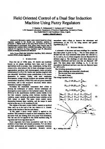
induction generator through a cycloconverter in the stator side. Abdel-halim, et. Al [17] suggested a method of controlling the induction generator such that the driving wind-turbine follows the point of maximum wind power. This is employed through dual control using a cycloconverter in the stator side and three added resistances in the rotor side. The present paper aims at improving the performance of the grid-connected induction generators at the different expected wind speeds through controlling both the stator and rotor sides. Controlling the stator side is done via a cycloconverter, while controlling the rotor side is done through adding resistances in the rotor circuit. This is achieved by connecting a bridge rectifier feeding a single resistance shunted by a dc chopper. This enables easier electronic control. This work adds to the efforts paid to develop usage of wind energy. The paper presents complete modelling of the CCIG, computes the performance characteristics, and compares the characteristics with those of the uncontrolled induction generator (UCIG). 2. System Description and Control Objectives 2.1 Induction Generator System The system under study comprises a variable-speed induction generator linked to the grid through a cycloconverter in the stator side, while fine control may be achieved by adjusting the resistance of the rotor circuit. This is carried out by adding a bridge rectifier feeding a resistance shunted by a dc chopper (Fig. 1). The rotor winding is periodically subjected to high external resistance RCL at the OFF times of control, and is subjected to low rotor resistance at the ON times of control. According to the ratio of the ''OFF'' period to the "ON" period, the rotor effectively sees a part of the resistance RCLadded in its circuit. Consequently, the motor torque-speed characteristic is changed and the speed is controlled.
Fig. 1: System schematic Diagram
Dual Control of Induction Generators for Tracing the Maximum Wind Energy
25
2.2 Wind Energy and Wind Turbines Wind turbines are mechanical devices specifically designed to convert part of the kinetic energy of the wind into useful mechanical energy. Depending on the position of the rotor axis, wind turbines are classified into vertical-axis and horizontal-axis ones [18].Nowadays, almost all commercial wind turbines connected to grid have horizontal-axis two-bladed or three-bladed rotors. Commonly, thrust force, torque and power are expressed in terms of nondimensional thrust (CT), torque (CQ) and power (CP) coefficients as follows [18,19].
(2.1)
(2.2)
(2.3)
(2.4)
Note that the three coefficients are written in terms of the pitch angle and the so-called tip-speed-ratio; λ, defined as
(2.5) Fig.2 shows typical variations of CQ and Cpfor a fixed-pitch wind turbine [18, 20].
M. A. Abdel-halim
26
Fig. 2: Typical variations of (a) CQ and (b) CP for a fixed-pitch wind turbine
2.3. Control Strategy The system under study enables either control of the stator cycloconverter only (SCIG) or combined control from the stator side through the cycloconverter in addition to adding resistances in the rotor side when necessary. The objective of the control strategy is to regulate the speed of the generator to force the turbine to operate as follows: At high wind speeds, the turbine is operated such that the generator works slightly higher than its nominal speed. In this case, the power extracted will be maximum at a certain wind speed (power base speed), and not over the whole range. At the power base wind speed, the output frequency of the cycloconverter is adjusted to be the nominal generator frequency. As the wind speed increases above the power base speed the frequency is kept constant at the rated value. The power extracted from the wind is not the available maximum power. At a certain wind speed higher than the power base speed, it happens that the torque extracted from the wind becomes the maximum available torque. This speed will be called the torque base speed (VwQ). As the wind speed exceeds the torque base speed, resistances may be added to the rotor of the generator to keep tracing the available maximum torque. 1. As the wind speed decreases below the power base speed, the frequency is kept at its rated value. This is the case until the wind speed reaches a value such that the torque extracted from the wind at a generator-speed near the nominal speed becomes half or less than the maximum torque that can be extracted from the wind. The output frequency of the cycloconverter is then adjusted to be half the generator nominal frequency. Rotor resistances may be added over the range starting from the wind speed of frequency switching down to a torque sub-base speed. At this speed
Dual Control of Induction Generators for Tracing the Maximum Wind Energy
27
the torque extracted is the maximum available torque without added rotor resistance. At wind speeds lower than the torque sub-base wind speed, operation continues at half the rated frequency without added resistances. 2. When the wind speed gets lower such that the torque extracted from the wind at a generator speed near half the nominal value becomes two-thirds the possible maximum extracted torque value, the output frequency of the cycloconverter is adjusted to be one-third the generator nominal frequency. The control strategy followed at lower wind speeds is similar, then, to that followed before. 3. Steady-State Modelling 3.1 Circuit Model Fig. 3 shows a frequency-domain per-phase circuit model of the 3-phase combinedcontrolled induction generator [3]. The generator is linked to the grid through a cycloconverter, with a possible-rotor added resistance.
Fig. 3: Per-phase equivalent circuit of the combined-controlled induction generator
Radd represents the possible added rotor resistance. X 1, X2 and Xm are functions of the output frequency of the cycloconverter and are given by: X=
𝜔𝑜 𝑛
𝐿
where, ωo is the generator rated angular frequency which is the input frequency to the cycloconverter, and n takes the values 1, 2, 3, .. to determine the cycloconverter output frequency ωo/n. For constant flux operation the output voltage of the cycloconverter is adjusted to keep constant voltage to frequency ratio. Thus, V 1 is given by Vr/n.
M. A. Abdel-halim
28 3.2 Mathematical Model
3.2.1 Induction Generator Model The induced torque of the induction generator is related to applied voltage, slip and the equivalent circuit parameters as follows[3]:
𝜏=
3 𝑉𝑇2 𝑅2𝑎 ⁄𝑆 𝜔𝑠 [(𝑅𝑇 + 𝑅2𝑎 /𝑆)2 + (𝑋𝑇 + 𝑋2 )2 ]
(3.1)
where R2a is the total rotor resistance; R2a = R2 + Radd, VT, RT and XT are the Thevenin'sequivalent circuit parameters of the stator. Neglecting Rc, these are given by
𝑉𝑇 =
𝑉1 𝑋 𝑚
√𝑅1 2 + (𝑋1 + 𝑋𝑚 )2
𝑅𝑇 + 𝑗𝑋𝑇 = (𝑅1 + 𝑗𝑋1 )// 𝑗𝑋𝑚
(3.2)
(3.3)
In case of adding resistances in the rotor circuit, the speed of the generator and hence its slip is related to the wind speed such that the tip speed ratio; λ, corresponds to the maximum torque coefficient; CQmax. This means that na/nso≅Vw/VwQ
(3.4)
The output current, active power, reactive power at a specified slip; S, and terminal voltage; V1, can be determined as usually done for the ac circuit analysis using the equivalent circuit. 3.2.2 Chopper Mathematical Model The three-phase rotor circuit, three-phase bridge rectifier and the chopper are connected in cascade. Circuit analysis will be done based on the following assumptions: 1. Effect of both overlap and rotor impedance voltage drop is neglected. 2. Forward voltage drops across thyristors and diodes are negligible. 3. High value for the rectifier-chopper linking inductance LCL is assumed. 4. Effect of the commutating capacitor on the rotor current is neglected.
Dual Control of Induction Generators for Tracing the Maximum Wind Energy
29
The idealized equivalent circuits of the chopper for both the ON and OFF states are shown in Fig. 3.2. Each equivalent circuit of the chopper is followed by the other as the ON and OFF states are repeated.
a)
On state equivalent circuit
b) OFF state equivalent circuit Fig. 4: Idealized equivalent circuit of a chopper
In the idealized equivalent circuit, R represents the total resistances of linking inductor, rectifier- and chopper- semiconductor devices. RCL is the chopper load resistance. Due to the chopping action, the dc source of Fig. 3.2 sees an equivalent resistance which draws the dc component of the rectifier output current. The value of this equivalent resistance can be expressed in terms of both the ON and OFF state equivalent circuit resistances and the chopper duty cycle; γ, as follow [21]: Req= γ RON + (1 – γ) ROFF
[3.5]
Then, the added resistance through the chopper to each phase of the rotor circuit is given by [29] Radd = 0.548 [γ RON + (1- γ) ROFF)] where, RON = R and ROFF = RCL + R
[3.6]
30
M. A. Abdel-halim
4. Results The mathematical model given in section 3 has been used to develop an M code program to enable the computation of the uncontrolled and the controlled induction generator performance characteristics. The program has been used to compute the characteristics of an induction generator having the parameters given in Tables 1 and 2[14, 22]. The generator performance characteristics have been determined over a wind-range of wind speed (2 m/s up to 10 m/s). Table 1: Main Characteristics of the Generator Nominal stator active power
2.5 MW
Nominal torque
15915 Nm
Nominal stator voltage, Vr
690 V
Nominal stator current
2330 A
Nominal rotor current
2459 A
Nominal speed
1500 rpm
Speed range
900–2000 rpm
Pole pairs
2
Table 2: Equivalent Model of the Generator
Magnetizing inductance; Lm
2.3mH
Rotor leakage inductance; L2
0.085mH
Stator leakage inductance; L1
0.085mH
Rotor resistance; R2
0.022 ohm
Stator resistance; R1
0.024 ohm
To evaluate the performance characteristics of the controlled induction generator, it will be helpful to compare it with the uncontrolled one. At a base wind speed (6.5 m/s in our case), the turbine extracts the maximum power from the wind, while the generator is normally driven without any control. λ (the tip speed ratio) at this wind speed corresponds to the maximum power coefficient (C pmax.). From the typical turbine curve, λ and Cpmax are found to be 0.63 and 0.455,respectively. The wind extracted power at this base wind speedis found to be 1.1 MW. This meant that at the highest expected wind-speed (10 m/sec in our case), the wind extracted power will be limited at the most to about 2.5 MW. Thus, the turbine and the generator will
Dual Control of Induction Generators for Tracing the Maximum Wind Energy
31
not be over-loaded. The performance characteristics for the uncontrolled induction generator (UCIG) are, then, determined using the following algorithm: a– The calculations is started from the highest assumed wind speed going down in steps b– λ is calculated assuming that the generator runs at a speed slightly higher than the rated synchronous speed. CQ is then obtained from the typical turbine curves. The induced torque is calculated at each wind speed using Eqn. 2.2. c– Once the torque is calculated, the slip is calculated using Eqn. 3.1. d– The output current, power factor, active power, reactive power and the efficiency are then calculated using the equivalent circuit (Fig. 3). The algorithm used for the stator-cycloconverter controlled induction generator (SCIG) is similar to that for the UCIG (a-d) then it continues as follows: e–While the wind speed goes down, we keep watching CQ, and once it happens that CQ becomes half its maximum value (CQmax), the input frequency and voltage applied to the generator by the cycloconverter are halved. f– The tip speed ratio (λ) is recalculated to correspond to half the rated synchronous speed. g–The calculations of CQ and the induced torque continue as before until CQ reaches two-thirds the maximum value. Then, the frequency and voltage applied to the generator are changed to one-third the rated value. h– Thereafter, the calculations continue, and the frequency is reduced again, and so on until the lowest wind speed is reached. The algorithm used for the combined controlled induction generator (CCIG) is similar to that of the SCIG except that at wind speeds higher than the torque base speed at the nominal frequency or the torque sub-base speed at the other frequencies, the extracted wind torque is assumed to be the maximum available value. This is achieved through adding resistances in the rotor circuit. The slip at these wind speeds is calculated such that it realizes the tip speed ratio that gives maximum extracted torque using Eqn. 3.4. The value of the seen added resistance per phase is calculated using Eqn. 3.1. Consequently, the chopper resistance RCL and the duty cycle are calculated using Eqns. 3.5 and 3.6. The performance characteristics of the UCIG, SCIG and the CCIG are shown in Figs. 5-18.
M. A. Abdel-halim
32 0.9 0.8 0.7
Power Factor
0.6 0.5 0.4 0.3 0.2 0.1 0
2
3
4
5
6
7
8
9
10
wind speed (m/sec) Fig. 5: Power factor versus the wind speed for UCIG 1 0.9
Power Factor
0.8 0.7 0.6 0.5 0.4 0.3 0.2
2
3
4
5
6
7
8
9
10
wind speed (m/sec)
Fig. 6: Power factor versus the wind speed for SCIG (f=50 Hz for V ≥ 4.5 m/s, f=50/2 Hz for 4.5 m/s>V>2.74 m/s, f=50/3 for V ≤ 2.74 m/s)
Dual Control of Induction Generators for Tracing the Maximum Wind Energy
2.5
Active power (MW)
2
1.5
1
0.5
0
2
3
4
5
6
7
8
9
10
wind speed (m/sec)
Fig. 7: Active power versus the wind speed for UCIG 2.5
Active power (MW)
2
1.5
1
0.5
0
2
3
4
5
6
7
8
9
10
wind speed (m/sec)
Fig. 8: Active power versus the wind speed for SCIG (f=50 Hz for V ≥ 4.5 m/s, f=50/2 Hz for 4.5 m/s >V >2.74 m/s, f=50/3 for V ≤ 2.74 m/s)
33
M. A. Abdel-halim
34 3
Active power (MW)
2.5
2
1.5
1
0.5
0
2
3
4
5
6
7
8
9
10
wind speed (m/sec)
Fig. 9: Active power versus the wind speed for CCIG (f=50 Hz for V ≥ 4.5 m/s, f=50/2 Hz for 4.5 m/s >V >2.74 m/s, f=50/3 for V ≤ 2.74 m/s)
-0.6
Reactive power (MVAR)
-0.7 -0.8 -0.9 -1 -1.1 -1.2 -1.3 -1.4
2
3
4
5
6
7
8
9
wind speed (m/sec)
Fig. 10: Reactive power versus the wind speed for UCIG
10
Dual Control of Induction Generators for Tracing the Maximum Wind Energy
0
Reactive power (MVAR)
-0.2
-0.4
-0.6
-0.8
-1
-1.2
-1.4
2
3
4
5
6
7
8
9
10
wind speed (m/sec)
Fig. 11: Reactive power versus the wind speed for SCIG (f=50 Hz for V ≥ 4.5 m/s, f=50/2 Hz for 4.5 m/s >V >2.74 m/s, f=50/3 for V ≤ 2.74 m/s)
-0.2
Reactive power (MVAR)
-0.4
-0.6
-0.8
-1
-1.2
-1.4
-1.6
2
3
4
5
6
7
8
9
10
wind speed (m/sec)
Fig. 12: Reactive power versus the wind speed for CCIG (f=50 Hz for V ≥ 4.5 m/s, f=50/2 Hz for 4.5 m/s >V >2.74 m/s, f=50/3 for V ≤ 2.74 m/s)
35
M. A. Abdel-halim
36
1
0.9
Efficiency
0.8
0.7
0.6
0.5
0.4
2
3
4
5
6
7
8
9
10
wind speed (m/sec)
Fig. 13: The generator efficiency versus the wind speed for UCIG 1 0.995 0.99
Efficiency
0.985 0.98 0.975 0.97 0.965 0.96 0.955 0.95
2
3
4
5
6
7
8
9
10
wind speed (m/sec)
Fig. 14: The generator efficiency versus the wind speed for SCIG (f=50 Hz for V ≥ 4.5 m/s, f=50/2 Hz for 4.5 m/s >V >2.74 m/s, f=50/3 for V ≤ 2.74 m/s)
Dual Control of Induction Generators for Tracing the Maximum Wind Energy
1 0.995 0.99
Efficiency
0.985 0.98 0.975 0.97 0.965 0.96 0.955 0.95
2
3
4
5
6
7
8
9
10
wind speed (m/sec)
Fig. 15: The generator efficiency versus the wind speed for CCIG (f=50 Hz for V ≥ 4.5 m/s, f=50/2 Hz for 4.5 m/s >V >2.74 m/s, f=50/3 for V ≤ 2.74 m/s)
2500 Stator current Rotor current
Current (Amp)
2000
1500
1000
500
0
2
3
4
5
6
7
8
9
wind speed (m/sec)
Fig. 16: Terminal current versus the wind speed for UCIG
10
37
M. A. Abdel-halim
38
2500 Stator current Rotor current
Current (Amp)
2000
1500
1000
500
0
2
3
4
5
6
7
8
9
10
wind speed (m/sec)
Fig. 17: Terminal current versus the wind speed for SCIG (f=50 Hz for V ≥ 4.5 m/s, f=50/2 Hz for 4.5 m/s >V >2.74 m/s, f=50/3 for V ≤ 2.74 m/s) 3000 Stator current Rotor current 2500
Current (Amp)
2000
1500
1000
500
0
2
3
4
5
6
7
8
9
10
wind speed (m/sec)
Fig. 18: Terminal current versus the wind speed for CCIG (f=50 Hz for V ≥ 4.5 m/s, f=50/2 Hz for 4.5 m/s >V >2.74 m/s, f=50/3 for V ≤ 2.74 m/s)
Dual Control of Induction Generators for Tracing the Maximum Wind Energy
39
Comparing the performance characteristics of the CCIG with those of the SCIG and the UCIG reveals the following: 1. The power factor curves for the UCIG and the SCIG (Figs. 5& 6) show that the power factor is enhanced by controlling the frequency such that when the frequency is changed at low wind speeds to 25 Hz, the power factor is improved and approximately ranges from 0.62 to 0.25 instead of approximately ranging from 0.45 to 0.02 at 50 Hz. When the frequency is changed to 16.67 (50/3) Hz at lower wind speed, the power factor is improved, and approximately ranges from 0.3 to 0.22 instead of approximately ranging from 0.02 to about 0.01 at 50 Hz. The effect of adding resistance on the power factor is negligible. 2. The output active power is increased when the frequency is changed to 25 Hz at low wind speeds such that it ranges from 0.25 MW to 0.1 MW, while the range was about 0.26 MW to 0.07 MW at 50 Hz. At lower wind speeds the output active power nearly vanishes if the frequency is kept at 50 Hz, while by changing the frequency to 16.67 (50/3) Hz, the output power ranges from about 0.1 MW to about 0.08 MW (Figs. 7& 8). Again the effect of adding resistances in the rotor is negligible at 25 Hz and lower frequencies, while it give noticeable effect at 50 Hz at the high wind speeds. For example, the active power increases from about 2.45 MW to about 2.75 MW at wind speed of 10 m/s (Figs. 8& 9). 3. The reactive power consumed by the generator is decreased by halving the frequency to nearly half its value at 50 Hz, and it is again decreased to one-third its value at 50 Hz (Figs. 10 and 11). Adding resistances in the rotor increases the consumed reactive power by about 10% (Figs. 11& 12). 4. The generator efficiency drops as the frequency is lowered by the cycloconverter (Figs. 13& 14). However this is unimportant as irrespective of the decreased efficiency the output power increases due to the increase of the captured mechanical power. Adding resistances in the rotor circuit somewhat reduces the generator efficiency (Fig. 15). 5. The terminal current jumps when the frequency and the voltage is lowered (Figs. 16& 17). Adding resistances has little effect at low frequency, however it increases the current at high wind speeds when the generator works at its nominal frequency (Figs. 16& 18). In the case of CCIG, a chopper has been designed. The value of the resistance of the on-state and that of the off-state have been determined according to the needed rotor added resistance per phase. This is performed by taking the maximum value of the added resistance which can be reflected by the chopper as 1.2 times the maximum required added resistance. The minimum required added resistance is set to be obtained at chopper duty cycle 0f 0.98. Using these two principles and Eqns. 3.5 and 3.6 the chopper load resistance is found to be 0.5757 ohm, while the total on state resistance is adjusted to 0.1543 ohm. The calculated values of the rotor perphase added resistance through the chopper and the necessary duty cycles of the chopper in this case is given in Table 3.
M. A. Abdel-halim
40
Table 3: Values of the added resistances in the rotor and the chopper duty cycles Wind speed, m/s
10
9.0
8.0
7.0
6.75
6.5
6.25
6
5
4.5
fch, Hz
50
50
50
50
50
50
50
50
50
50
Ra, ohm
0.3335
0.1972
0
0
0
0
0
0
0
0
Chopper Duty Cycle
0.211
0.643
-
-
-
-
-
-
-
-
Wind speed, m/s
4.3
4.2
4.1
4.0
3.5
3.0
2.74
2.67
2.5
2.25
fch, Hz
25
25
25
25
25
25
25
16.67
16.67
16.67
Ra, ohm
0.2926
0.1966
0.0909
0
0
0
0
0
0
0
Chopper Duty Cycle
0.341
0.645
0.98
-
-
-
-
-
-
-
5. Conclusion The present paper aims at optimizing the performance of a wind-driven induction generator at the different expected wind speeds employing control techniques in both the stator side and the rotor side. The control in the stator is done via a cycloconverter, while the control in the rotor side is done through the simple method of adding resistances in the rotor circuit.The combined-controlled induction generator has been modelled at steady-state conditions using frequency domain equivalent circuits. Computer-programs have been developed to compute the performance characteristics of the combined-controlled induction generator (CCIG) and the uncontrolled induction generator (UCIG).Comparing the performance characteristics of the UCIG and the SCIG reveals the following: 1. The power factor is enhanced by controlling the frequency at low wind speeds. 2. The output active power is increased when the frequency is lowered at low wind speeds. 3. The reactive power consumed by the induction generator almost decreasesin proportion to the frequency of the generator applied frequency. 4. The generator efficiency drops as the frequency is lowered by the cycloconverter. However this is unimportant as irrespective of the decreased efficiency the output power increases due to the increase of the captured mechanical power.
Dual Control of Induction Generators for Tracing the Maximum Wind Energy
41
Adding rotor resistances has negligible effect at low wind speed. The effect at high wind speeds appears on the delivered active power which somewhat increases, and on the consumed reactive power which somewhat increases. The power factor is almost unaffected. 6. Acknowledgment The authors are grateful to the Scientific Research Deanship at Qassim University for the financial support through this research. 7. References [1] Bhim Singh “Induction Generators-A prospective”, Electrical Machines and Power Systems, Vol. 23, 1995, pp. 163-177. [2] V. Subbiah V. and Geetha, K., “Certain Investigations on a Grid Connected Induction Generator with Voltage Control”, Proc. of the IEEE International Conference on Power Electronics, Drives and Energy Systems, New Delhi, India. Jan.1996, pp. 439-444. [3] Akhmatov, V., "Induction Generators for Wind Power", Multi-Science Publishing Co. Ltd., Essex, United Kingdom, 2005. [4] Abdel-halim, M. A., “Solid-state control of a grid connected induction generator”, Electric Power Components and Systems Journal, Vol. 29, No. 2, 2001, pp. 163-178. [5] Almarshoud, A. F., Alolah, A. I. and Abdel-halim, M. A., “Performance of Grid Connected Induction Generator under Naturally Commutated AC Voltage Controller”, Electric Power Components and Systems, Vol.32 (7), 2004, pp. 691-700. [6] Almarshoud, A. F., Alolah, A. I. and Abdel-halim, M. A., “Analysis and Operation of Non-Isolated Three-Phase Induction Generator Controlled by a Transistorized ac Converter”, Proc. of the IEEE Aegean Conference on Electrical Machines and Power Electronics (ACEMP), Istanbul, Turkey, May 2004. [7] Abdel-halim, M. A., Almarshoud, A. F. and Shees, M. M. “Analysis of the Electro-Mechanical Performance of Network-Connected Induction Generators Governed by Different AC Voltage Controllers", Qassim University Scientific Journal- Engineering and Computer Sciences, Vol. 4, No. 1, 2011, pp. 41-66. [8] Carlos, R., “Current Control in the Grid Connection of the Double-Output Induction Generator Linked to a Variable Speed Wind Turbine”, Industrial Electronics Conference (IECON), Vol. 2, 2002, pp. 979-984.
42
M. A. Abdel-halim
[9] Ruben, P., “A Cage Induction Generator using Back to Back PMW Converters for Variable Speed Grid Connected Wind Energy System”, Industrial Electronics Conference (IECON), Vol.2, 2001, pp. 1376-1381. [10] Holdsworth, L., Wu, X. G., Ekanayake, J. B. and Jenkins, N.“Comparison of Fixed Speed and Doubly-Fed Induction Wind Turbines during Power System Disturbances”, IEE Proceedings Generation, Transmission, and Distribution, Vol. 150, No. 3, May, 2003, pp. 343-352. [11] Fernandez, L. M., Garcia, C. A., Jurado, F. and Saenz, J. R., “Aggregation of Doubly Fed Induction Generators Wind Turbines Under Different Incoming Wind Speed”, Proceedings of St. Petersburg Power Tech Conference, St. Petersburg, Russia, June, 2005, pp. 27-30. [12] R. G. De Almeidam, R. G. and Pecas Lopes J. A., “Primary Frequency Control Participation Provided by Doubly Fed Induction Wind Generators”, Proceedings of the Power System Computation Conference (PSCC), Liege, Belgium, August, 2005, pp. 22-26. [13] Shaltout, A. A. and El-Ramahi, A. F., "Maximum Power Tracking for a Wind Driven Induction Generator Connected to a Utility Network", Applied Energy, Vol. 52, 1995, pp. 243-253. [14] Abdel-halim, M. A., Mahfouz, A. A. and Almarshoud, A. F., "Enhancing the Performance of Wind-Energy-Driven Double-Fed Induction Generators", Qassim University Scientific Journal- Engineering and Computer Sciences, Vol. 7, No. 1, 2014, pp. 23-41. [15] Boumassata, A.,Kerdoun, D., Cherfia, N. and Bennecib, N. "Performance of Wind Energy Conversion Systems Using A Cycloconverter to Control A Doubly Fed Induction Generator", Energy Procedia, Available online at www.sciencedirect.com,Vol. 42, 2013, pp. 143–152. [16] Swati Devabhaktuni, Jayaram, S. V., Kumar, "Stator Flux Oriented Vector Control of Wind Driven Self Excited Induction Generator Connected to Grid through Cycloconverter, Innovative Systems Design and Engineering, Available online, Vol. 3, No. 1, 2012, pp. 70-78. [17] Abdel-halim, M. A., Mahfouz, A. A. and Almarshoud, A. F.,“Enhancing the Performance of a Stator and Rotor Combined-Controlled Wind-Driven Induction Generator,” Accepted for publication in Journal of King AbdulAziz University- Engineering Sciences, SA. [18]Ackermann, T. and Soder, L., "An overview of wind energy-status," Renewable and Sustainable Energy Reviews,” Vol. 6 (1-2), 2002, pp. 67–127. [19] Bossanyi, E., "The design of closed loop controllers for wind turbines," Wind Energy, Vol.3 (3), 2000, pp. 149–163.
Dual Control of Induction Generators for Tracing the Maximum Wind Energy
43
[20] Leithead, W. and Connor, B., "Control of variable speed wind turbines: design task," International Journal of Control, Vol. 73 (13), 2000, pp. 1189–1212. [21] Ahmed, F. A., Abu Shady, S. and Abdel-halim, M. A “Speed control of induction motor using a modified chopper in the rotor circuit,” Scientific Engineering Bulletin, Faculty of Engineering, Cairo Univ., Vol. 37(2), 1990, pp. 535-550. [22] Boldea, I. and Nasar, A. “The inductin Machine Handbook”, CRC Press, 2006.
44
M. A. Abdel-halim
[email protected]