Research Signpost 37/661 (2), Fort P.O., Trivandrum-695 023, Kerala, India
Mesoscopic Tunneling Devices, 2004: ISBN: 81-271-0007-2 Editor: Hiroshi Nakashima
3
Single-electron logic based on multiple-tunnel junctions S. Amakawa1 , K. Tsukagoshi2*, K. Nakazato2, H. Mizuta2 and B. W. Alphenaar2# 1 Microelectronics Research Centre, Cavendish Laboratory, University of Cambridge Madingley Road, Cambridge CB3 0HE, United Kingdom; 2Hitachi Cambridge Laboratory Cavendish Laboratory, Hitachi Europe Ltd., Madingley Road, Cambridge CB3 0HE, United Kingdom
Abstract This is a review of our work on logic circuits based on electron pumps which consist of semiconductor multiple-tunnel-junction (MTJ) singleelectron transistors. The MTJ transistors are formed in side-gated GaAs wires δ-doped with Si. Being semiconductor, the MTJ transistor not only works as a single-electron transistor but can also be completely pinched off to an off state that is far better than is achievable by Coulomb blockade alone. This added degree of controllability, missing in the metallic counterpart, gives distinct on-off characteristics even at relatively high temperatures. MTJ pumps are used to implement a binary decision diagram (BDD) logic circuit. The two-way switching function required in the BDD circuit is realised by using the pinch-off state. A simple theoretical analysis is carried out to estimate the best possible performance of the pump. Present addresses: *RIKEN, Hirosawa 2-1, Wako, Saitama 351-0198, Japan; #Electrical and Computer Engineering, University of Louisville, Louisville, KY 40292 USA Correspondence/Reprint request: S. Amakawa, Microelectronics Research Centre, Cavendish Laboratory, University of Cambridge Madingley Road, Cambridge CB3 0HE, United Kingdom. E-mail:
[email protected]
2
S. Amakawa et al.
The reasons behind adopting such a circuit architecture are discussed in detail.
1 Introduction Numerous proposals have been made of logic applications of single-electron devices, of which we can cite only some [1–18]. Some are analogous to existing circuit architectures, and some try to be more “single-electron” specific. However, no single approach seems to stand out as a winner. In this article, we review an approach we took and discuss the design decisions. A key ingredient in our approach is the use of semiconductor multiple tunnel junctions (MTJs). MTJs are very effective for preventing leakage due to cotunnelling [19]. In addition, semiconductor single-electron devices [20,21] offer some more useful features than metallic devices. Our MTJs are implemented in very narrow side-gated GaAs constrictions heavily δ-doped with Si. When a negative voltage is applied to a side-gate, the two-dimensional electron gas (2DEG) is split into microsegments due to potentials of dopant atoms, and typically more than five tunnel junctions are formed in series. [22– 25]. Within a certain range of side-gate bias voltage, the MTJ can be gated to work as a single-electron transistor. With still higher negative side-gate voltages, the channel is completely pinched off. In the next section, we explain some basics of single-electron devices. In §3, we discuss some points which we considered when designing our single-electron logic circuit. Experimental results are presented in the following three sections. Experimental investigation of the multi-clock MTJ pump, which is an essential component of our circuit, is described in §4. Experiment on two-way switching operation, required in the circuit, receives treatment in §5. The demonstration of a single-electron logic circuit is presented in §6. §7 deals with a simple performance analysis of the multi-clock MTJ pump. Finally in §8 we discuss some prospects for the future.
2 Semiclassical theory The characteristics of our MTJs are well-described by the semiclassical theory of single-electron charging and Coulomb blockade of single-electron transfer.
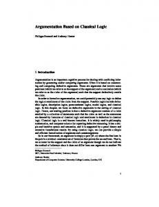
2.1 Coulomb blockade Electrical characteristics of various voltage-biased circuit elements are compared in Fig. 1 [23]. In a resistor, carriers respond to any small change of voltage, and a current flows as shown in Fig. 1(b). In a capacitor, no steady current flows as shown in Fig. 1(c). An ideal voltage-biased ultrasmall tunnel junction would show a similar currentvoltage characteristic to a resistor’s, as shown in Fig. 1(d). If the junction is very small and the barrier is quite opaque,1 it is reasonable to assume that the current flows by successive tunnelling of single electrons. The charge lost by tunnelling is immediately supplied by the voltage source through the ideal leads (the global rule [26]), and the electro-static energy U of the system remains constant; U = CV2 /2. Therefore, there is _______________________________________ 1
Opaque here means that the tunnel resistance RT in Fig. 1(d) is larger than the resistance quantum.
short title
3
Figure 1. I-V characteristics of ideally voltage-biased circuit elements as in (a). (b) Resistor. (c) Capacitor. (d) Ultrasmall tunnel junction. (e) MTJ.
no correlation between tunnelling events. Suppose that the circuit is in thermal equilibrium with the environment at temperature T. Then, in a steady state, the forward direction single-electron tunnelling rate Γ+ and the rate for its reverse process Γ- should satisfy the following detailed balance relationship. (1) Here e is the elementary charge, and eV is the amount of energy dissipated to the environment by forward tunnelling and equals the amount of work, ∆We, done by the voltage source. Dissipation is assumed to take place by some (unspecified) fast physical processes. The net electron transfer rate in the forward direction is (2) whence the current is (3) From Eqs. (2) and (3), the rate of forward tunneling is [27]
4
S. Amakawa et al.
(4) In the popular “tunnel resistance” model, the current-voltage relationship is approximated by an Ohmic relationship I(V) = V/RT, as shown by the broken line in Fig. 1(d).2 The characteristic of an MTJ looks like a combination of both resistor and capacitor characteristics as shown in Fig. 1(e). When V is smaller than a certain value, no tunnelling event takes place in any of the tunnel junctions at T → 0 K. To see how this can happen, we again look at the tunneling rate. Since in this case each tunnel junction is no longer voltage-biased, Eq. (4) cannot be used as is. The difference here is that when an electron tunnels, part of the energy supplied from the voltage source is not immediately dissipated but stored in the capacitances of tunnel junctions, that is to say, ∆U ≠ 0. By the principle of conservation of energy (the first law), (5) where đQirrev is the heat added to the system, and hence −đQirrev is the energy transferred to the environment [28]. Let us introduce an energy function F as follows.3 (6) Then, đQirrev = ∆F = Ff − Fi, where Ff and Fi are the values of F after and before tunnelling, respectively. In the case of a voltage-biased tunnel junction, Fig. 1(d), ∆U happened to be zero, so that ∆F = −∆We = −eV < 0. ∆F < 0 means that some energy is dissipated to the environment. In an MTJ, however, ∆F can become positive even when ∆We > 0 if ∆U > 0. 4 This can happen if V is within a certain range. Processes with ∆F > 0 are suppressed because of the second law. As a result, a gap appears in the I-V curve as shown in Fig. 1(e). This phenomenon is called Coulomb blockade of single-electron tunnelling because the Coulomb energy plays a key role in suppressing tunnelling.5 In the absence of tunneling events, no energy dissipation takes place in equilibrium, and therefore F takes an extremum. Since F reaches the extremum by dissipating energy (∆F < 0), it is a minimum. In this respect, F is analogous to a free energy. However, unlike Helmholtz or Gibbs free energy in thermodynamics, Eq. (6) is not a function of state because it includes work, which is not an attribute of the system but depends on the history of the system. Alternatively, Eq. (6) may also be understood as the sum of electrostatic energy and available chemical energy in “batteries” (Uchem = const − We). In any case, what usually matters is only the difference in F, viz. ∆F. _________________________________________ 2
If one wishes to stick to the concept of tunnel resistance even for non-Ohmic I(V), the bias-dependent tunnel resistance would be RT(V) = ∂I/∂V . F is sometimes called electrostatic energy in the literature. In this article, we refer to U as electrostatic energy. 4 ∆F > 0 can also be met (very easily) if ∆We < 0, but this is not a special situation at all. This is a situation where an electron is trying to tunnel against a bias. Such a tunnelling event is obviously forbidden. 5 In fact, the single-charge transfer need not take place by tunnelling. For example, thermal hopping also gives similar results [29]. 3
short title
5
Now the eV in Eq. (4) has to be replaced by −∆F to give (7) where (8) Veff is the effective bias voltage across the tunnel junction in question [30]. Vi is the voltage across the junction before tunnelling and Vf is that after tunnelling.6 Equation (7) is plotted in Fig. 2.
Figure 2. Tunnelling rate Γ as a function of ∆F = −eVeff. I(V) = V/RT is assumed.
Note that it has been assumed in the above that the energy level spacings in the MTJ islands are the same (continuous) as in the case of a voltage-biased junction. If this is not the case, tunneling between individual energy levels should be considered [31–34]. In such cases, it is common to look at the zero-bias conductance of the entire structure (transistor) [33, 35–37].
2.2 Single-electron transistor A circuit diagram of a capacitively-coupled single-electron transistor [10] with two tunnel junctions is shown in Fig. 3. Its Coulomb blockade (stability) condition at absolute zero is derived as follows. Supposing that all bias voltages are fixed, the electrostatic free energy Eq. (6) may be written as
(9) ______________________________________ Vi ≠ Vf if ∆U ≠ 0.
6
6
S. Amakawa et al.
Figure 3. Two-junction single-electron transistor with a capacitively-coupled gate. m1 and m2 are the numbers of charges that have tunneled through C1 and C2, respectively. qb is the background charge.
where m1 and m2 are the numbers of charges that have tunnelled through junctions C1 and C2, respectively. The charge on the central island satisfies (10) where qb is the background charge which gives fractional offset to the island charge. Also, the voltage differences between electrodes can be written in terms of Qi using Kirchoff’s voltage law. By eliminating all the Qi in Eq. (9), we obtain
(11) where (12) The constant term in Eq. (11) does not contain m1 nor m2. The total capacitance of the dot, CΣ, rather than tunnel capacitances, determines the characteristic energy scale e2/CΣ, and hence the operation temperature. The stability condition for the neutral state (m1 − m2 = 0) is given by F(±1, 0) − F(0, 0) > 0 and F(0, ±1) − F(0, 0) > 0. 7 In the present case, the three voltage sources V1, V2 ___________________________________________ 7 These inequalities only define the stable region for the state m1 − m2 = 0 and do not explicitly assert the instability of the region outside the said stable region. However, it is straightforward to confirm the instability of, say, m1 − m2 = 1 by noticing F(1, 1) − F(1, 0) = F(0, 0) − F(0, − 1), etc.
short title
7
and Vg span a three-dimensional space. Two different cross sections of the stable region are shown in Fig. 4 as shaded areas. When Vg is swept, (m1 − m2)e in the first term of Eq. (11) changes such that it cancels out CgVg. As a result, the current changes periodically as shown in Fig. 5. The current I changes so sensitively on CgVg (especially near the border of stability) that a single-electron transistor can be used as an electrometer [38]. In the I-V1 plane, the “Coulomb gap” around V1 = 0 [Fig. 1(e)] repeatedly stretch and shrink with Vg.
Figure 4. Stability diagrams of the single-electron transistor. Shaded areas are the Coulomb blockade regions, and current is blocked at T = 0 K. Background charge qb is assumed to be zero. (a) V1-Vg plane at V2 = 0. The cross section at V1 = 0 (V2-Vg plane). can be obtained by substituting V2, C1 and C2 for V1, C2 and C1, respectively. (b) V1-V2 plane. The rhomboid moves along the line V1=V2 if Vg is changed. After [28].
8
S. Amakawa et al.
Figure 5. Current of a single-electron transistor when small bias V1 is applied. It oscillates with the period e/Cg as Vg is swept. V2 = 0 is assumed.
2.3 Frequency-locked charge transfer Time-correlated single-electron tunnelling was observed in arrays of tunnel junctions irradiated with microwave fields [39, 40], where the intervals between tunnelling events were almost the same. Later, frequency-locked single-electron transfer by external gating was realised in the turnstile device [41]. The single-electron turnstile is an array of four tunnel junctions with a gate which is capacitively coupled to the island in the middle of the array, as shown in Fig. 6(a). The turnstile was designed so that only one extra electron can enter/leave the central island if a proper rf signal is applied to the gate. When an rf clock signal of frequency f is applied, a current plateau of I = ef appears within a certain range of bias voltage [41]. The following years saw various rf-driven
Figure 6. Various frequency-locked single-electron transfer devices. (a) Single-electron turnstile [41]. (b) Single-electron pump [45]. (c) Bidirectional MTJ pump [67]. (d) Multi-clock MTJ pump [71].
short title
9
single-electron transfer devices. Another kind of turnstile device was demonstrated in semiconductor [42]. It had two tunnel barriers and an island in between like a singleelectron transistor (Fig. 3), and the barriers were modulated by two rf signals with different phases to alternately lower the barriers [43]. This type of turnstile is also known as the oscillating-barrier turnstile [44], and its operation principle is somewhat different from the original turnstile [41]. The single-electron pump [45,46], driven by two or more rf clock signals, allows more precise single-electron transfer. In contrast to the turnstile device [41], no dc bias is required for frequency-locked electron transfer. It is also possible to pump up electrons against a small bias voltage. Another difference from the turnstile is that in the pump, electrons could in principle be transferred quasi-statically (tunnelling with ∆F = 0), whereas in the turnstile the charge transfer process is always dissipative [47]. The first single-electron pump had three tunnel junctions as shown in Fig. 6(b) and was driven by two rf signals [45, 46]. Accuracy of the frequency-locked current can be improved by the use of many tunnel junctions and driving rf-signals. The turnstile and the pump opened up a realistic possibility of establishing frequency-determined current standard [48] and other applications [12, 49]. Great efforts have been made to establish accurate charge transfer and to understand the mechanisms which hinder it [50–66]. The bidirectional electron pump reported by Tsukagoshi et al. consists of a pair of MTJ transistors connected in series [67, 68] as shown in Fig. 6(c). It is driven by one ac clock signal and resembles the turnstile [41] at first glance. Indeed, electron transfer is dissipative as in the turnstile [47]. However, it can pump up electrons against a small bias [67] like the original single-electron pump [45]. Moreover, the direction of pumping can be changed by properly adjusting the side-gate biases [67, 68]. The number of electrons transferred per clock cycle is typically a few tens to several hundred. These differences originate in the magnitude of capacitances in a device. In the original turnstile and pump, all the capacitances in a device are of the same order. On the other hand, there are two different capacitance scales involved in the bidirectional pump. One is of the capacitances that constitute the MTJs and the other is of the capacitance of the clocking-gate. The clocking-gate capacitance, which is situated between the MTJ transistors, is significantly larger than the other capacitances in the pump. The total capacitance of the clocked node is so large that single-electron charging effect is almost negligible. As a result, the MTJ transistors work virtually independently of each other as if being voltage-biased. The pump operation reflects MTJ transistors’ nonlinear I-V characteristics [Fig. 1(e)] rather than the precise charge configuration in the circuit [67, 68]. In other words, the bidirectional pump is essentially a series connection of two acbiased single-electron transistors [69], which work as rectifiers.8 Detailed analysis of the bidirectional pump was carried by Jalil et al. [68] using the semiclassical model. We later reported a similar MTJ pump [71]. It consists of three or more MTJs as shown in Fig. 6(d) and is driven by unipolar multi-phase clock signals. This is the pump which we used as a building block to construct a logic circuit [72]. Its operation also relies on the nonlinear current-voltage characteristics of MTJs, but the direction of pumping is determined by the choice of the phase difference between clock pulses. Details will be described in later sections. ______________________________________ 8
A similar kind of rectifier includes the quantum-dot ratchet [70].
10
S. Amakawa et al.
3 Design considerations There are a number of issues that should be considered to realise single-electron logic. Some are interrelated.
3.1 Information representation One most straightforward way of representing bit information is to use a certain number of excess electrons for “1” and the absence of them for “0,” although this is certainly not the only option [73]. The ultimate single-electron logic sounds very attractive. However, the number of charges used to represent a bit should be at least three. If a bit is represented by presence or absence of one extra charge, only one tunnelling event would result in bit flip. If only two charges are used, one tunnelling event would lead to the intermediate state with one extra charge, from which error recovery is not possible. With three charges, off-by-one errors could be corrected. More than three is still better, but we certainly do not want to increase the number indefinitely.9
3.2 Interaction between components A circuit component (element) that works nicely on its own (i.e. when biased by voltage sources) might not work as expected in a more complex circuit. Elements might interact with one another in a non-obvious way if the capacitance of the node which connects them together is small [75]. For instance, the CMOS-like inverter proposed by Tucker [16] may not work as an inverter if the capacitance of the node between the ptype and the n-type single-electron transistors is too small [76].10 This is because the interconnecting node makes some additional contribution to the electrostatic energy U in Eq. (6), which in turn affects the tunnelling rate, Eq. (7). This not only makes the design of large circuits difficult but also makes SPICE-type circuit simulation impractical [75, 77]. Besides, such circuits would inevitably have very tight tolerances for circuit parameter dispersion, and any unexpected stray capacitances may lead to a failure. Components should therefore be made independent of one another by requiring that the interconnecting nodes have relatively large capacitances. In the bidirectional [67,68] and multi-clock [28] MTJ pumps, the MTJ transistors are independent in this sense.
3.3 Transistor gain If single-electron transistors are to be used in a similar fashion to conventional transistors [4, 16], they must have voltage gain much greater than unity. This guarantees signal propagation with signal-level recovery. Let Vc be the voltage of the central island of a single-electron transistor (Fig. 3). Then, ∂Vc/∂Vg = Cg/CΣ and ∂Vc/∂V1 = C1/CΣ, where CΣ is given by Eq. (12). The voltage gain is maximised when a fixed current is flowing. If the fixed current I is small, I is almost proportional to Vc. Then the voltage gain is [10, 78] (13) ___________________________________________ 9
If the charge number is not too small, then the bit energy is a more important parameter than the number itself for reliability [74]. The number should nevertheless be kept small for speed. 10 In this example, the elements are the single-electron transistors, and the circuit is the inverter.
short title
11
where V2 is assumed to be grounded. Equation (13) suggests that Cg should be made much larger than C1. However, C1 is a tunnel capacitor which has a very thin insulating layer, whereas Cg is a non-tunnel capacitor, so that it is difficult to make Cg » C1. Relatively high voltage gains of transistors and inverters reported so far [79–84] are still far from ideal for real applications. Also, making Cg large contradicts the requirement that CΣ be as small as possible to have a large charging energy. Since the gain rapidly decreases as the temperature rises, the requirement of gain imposes a severe upper limit to the operation temperature. Conversely, if single-electron transistors are used in a way that does not require gain, operation temperature could be much higher. Therefore, architectures which do not require transistor gain are preferable.
3.4 Turn-off mechanism Although Coulomb blockade of single-charge transfer can in principle keep current from flowing for small biases [Fig. 1(e)], it is not a very good “turn-off” mechanism for practical purposes. The blockade region is determined by capacitance parameters as shown in Fig. 4. However, the tunnelling rate for ∆F > 0 is quickly lifted up from zero when T > 0 K as illustrated in Fig. 2. Leakage due to co-tunnelling [19] becomes a problem only after thermal leakage is eliminated [85]. Although a constant tunnel resistance is used in Fig. 2, the actual I(V) in Eq. (7) may be temperature dependent [29, 86, 87], making the leakage current even larger. In order to realise a good “turn-off” state, which is important for proper circuit operation and reduction of power dissipation, some different mechanism should be used in concert or instead. Good “turn-off” can be realised more easily in semiconductor single-electron devices than in metallic devices. If an extreme gate bias is applied, the conduction channel can be completely pinched off, and a very wide, high-resistance region (“gap”) appears as schematically shown in Fig. 7. The “turn-off” thus obtained is much better than that by Coulomb blockade.
Figure 7. A schematic stability diagram of a semiconductor single-electron transistor.
In some cases, enhancement of Coulomb blockade could be observed in an intermediate gate voltage range, where the gap is much wider than the normal Coulomb gap, and also the current oscillations persist with roughly the same period in Vg as in normal Coulomb blockade [13, 81, 88]. The origin of the enhancement is presumed to be the formation of space-charge regions around the tunnel junctions [81, 88]. This effect is also useful for improving voltage gain [81, 88].
12
S. Amakawa et al.
3.5 Background charge Random background charge, which gives some un-predictable offset to the island charge, is one of the most serious problems in the application of single-electron devices. As is clear from Eq. (11), the background charge qb on an island has exactly the same effect as CgVg, and therefore qb shifts the threshold gate voltage for Coulomb blockade. A single-electron transistor, which is extremely sensitive to CgVg, is equally sensitive to qb. Background charge often fluctuates with time, and in such a case the effect is recognised as noise [89–91]. Possible origins include charged defects and impurities in the substrate. Recently long-term background-charge stabilities in Si-based singleelectron devices have been reported [92,93]. Short-term noise and long-term drift are considered to have different origins [92]. Nakazato and Ahmed proposed the use of MTJs as a possible means by which to address the background charge problem [13]. Here we discuss in exactly what sense this could be a practical solution. In the analyses reported previously, it has commonly been assumed that the background charges on islands in an MTJ are statistically independent from one another [Fig. 8(a)] and take completely random values [94–96]. The question is whether such modelling appropriately describes real devices, especially semiconductor devices. We are inclined to postulate that apparently random background charges are actually correlated [97] as shown in Fig. 8(b). In state-of-the-art Si process technologies, for instance, a defect density of 0.01 cm−2 and a surface trap density of 1010 cm−2 have been achieved.11 Then the number of stray charges in close vicinity to an MTJ is most likely at most a few, and background charges should not be completely random. Coulomb blockade may be lifted in some junctions near a stray charge. However, Coulomb blockade in the rest of junctions should not be affected, thereby still maintaining a finite Coulomb gap [97]. If MTJs are used in a circuit architecture in which only the existence of the Coulomb gap is essential, the background charge problem could be circumvented with “correct nanofabrication techniques [100].”
Figure 8. Models of background charges in an array of tunnel junctions. (a) Background charges qb1, qb2, qb3, … are statistically independent and take completely random values. (b) qb1, qb2, qb3, … are correlated, characterised by a parameter (or a set of parameters) λ associated with a stray charge q(λ) at a nearby site.
______________________________________________ 11 Although the MTJ pumps described in this article are GaAs-based, Si MTJ pumps have also been demonstrated [98, 99].
short title
13
3.6 Our strategy We proposed a single-electron logic circuit that addressed most of the problems which we discussed above [72]. Our method is to use an architecture based on the binary decision diagram (BDD) [101]. A BDD has a tree structure which consists of nodes with a “two-way switching” function and can represent any logic function. The BDD tree shown in Fig. 9(a) represents an AND function. Each two-way switching node receives a “token”12 from the preceding node through the entry lead and then sends it to a following device through one of the branches in accordance with the input to the node [X1 or X2 in Fig. 9(a)]. The node devices need not have high gain, but only a distinct on-off switching characteristic is required. The use of BDD architecture for single-electron circuits was first proposed by Asahi et al. [102] Their proposed implementation was of an ultimate single-electron type in which one electron was used as the token [3, 103]. For the reasons discussed earlier, our implementation is different and is based on the multi-clock MTJ pumps [71], shown in Fig. 9(b)(c). Typically several hundred electrons flow per clock cycle rather than one. Electrons flow only by clocking, and no dc power supply is used for charge transfer, which might result in lower power consumption due to absence of steady leakage. Each MTJ transistor works as if being voltage-biased because of the large total capacitances of the clocked nodes [28], so that many pumps can be connected
Figure 9. (a) A BDD representing the AND logic function. (b) An AFM image of the AND function device. Ti/Au Schottky gates cover the 0.3 µm wires to form MTJs. The gates on the wide pads are used for clocking. (c) An equivalent circuit of the device including measurement equipment. (d) Truth table relating input to output for the AND device. Reprinted with permission from [72]. Copyright 1998, American Institute of Physics.
___________________________________ 12
Referred to as “messenger” in [3].
14
S. Amakawa et al.
with ease to constitute complex BDD trees. As mentioned in §2.3, the operation of the multi-clock MTJ pump relies on the nonlinear current-voltage characteristics of the component MTJs [Fig. 1(e)] rather than precise conditions for Coulomb blockade. It works as long as a Coulomb gap exists. Our circuit is therefore quite tolerant for dispersion of circuit parameters, including background charges and other uncontrollable effects such as quantum mechanical effects. This also means that it does not require subtle tuning of side-gate biases, which is commonly required. In fact, the necessity to fine-tune the gate voltage of each individual transistor, which can actually be done for only very small circuits, is a problem that hamper many proposed circuit architectures from being practical. Since our MTJ is naturally formed in an electrically squeezed semiconductor channel, its overall size is much smaller than those made by connecting many single tunnel junctions [40, 104, 105]. In the implementation of Asahi et al., Coulomb blockade alone was used for switching [3, 103]. In our implementation, we make use of the extra degree of controllability available in our MTJ, namely the pinch-off state, to realise the two-way switching function [106]. It provides much better “turn-off” than Coulomb blockade up to much higher temperatures. An implementation of BDD reported later by Yamada et al. [107] uses a similar idea in which resistance of tunnel junctions are modulated.
4 Multi-clock MTJ pump The multi-clocked MTJ pump is the building block of our logic circuit. Figure 10(a) shows a scanning electron micrograph of a multi-clock pump composed of three MTJs with two clocked nodes (node1 and node2) [71], corresponding to Fig. 6(d). The device was made from a δ-doped GaAs wafer. The Si δ-doped layer was 30 nm below the
Figure 10. Scanning electron micrograph of a multi-clock MTJ pump device with two clocked nodes. After [71].
short title
15
surface. The structure was defined by electron-beam lithography and reactive ion etching. A proper negative voltage applied to a side-gate electrically squeezes the conduction channel and splits it into series of islands with tunnel junctions in between [108]. The size of the islands varies, but the typical size was estimated to be about 10 nm in diameter. Further negative side-gate bias completely pinches off the conduction channel. In this experiment, the three MTJs were set in the Coulomb blockade regime. To transfer electrons, two clock signals (Vp1 and Vp2) of frequency f were applied to the side-gates with various phase delays δt. We experimentally investigated the optimum phase delay between the two voltage pulses. The pulse height Vp was high enough to overcome the Coulomb gap of the MTJs. The resulting pump current was measured at 1.8 K under zero source-drain bias with a current preamplifier. Figure 11 shows the net pump currents as a function of the phase delay δt over one clock cycle 1/f for different pulse shapes. As δt was increased, pump currents appeared
Figure 11. Pump currents versus the phase delay δt between Vp1 and Vp2. The driving frequency f is 0.5 MHz, and the pulse height Vp is 0.5 V. The insets show the pulse overlap conditions which give the maximum currents. (a) Triangular pulses. (b) Trapezium pulses. (c) Slightly tapered square pulses. Reprinted with permission from [71]. Copyright 1997, American Institute of Physics.
16
S. Amakawa et al.
and peaked at particular phase delays, where the falling part of Vp1 exactly overlapped with the rising part of Vp2 as illustrated in the insets of Fig. 11. The troughs in currents can be understood as the opposite combination of the pulses where the rising part of Vp1 overlapped with the falling part of Vp2. For phase delays with-out overlap, however, no pump current was observed. For instance, no current is produced if the two pulses are synchronised (δt = 0) because the voltage drop across MTJ2 is always zero. For efficient pumping, overlap of the pulses has to be optimised. For Fig. 11(a)– (c), triangular, trapezium, and slightly tapered square pulses were used, respectively. The pulse widths (tw in Fig. 10) were the same. Although the pump currents were maximised at different δt values, the pulse overlapping conditions for the maxima were the same for all the pulse shapes, as illustrated in the insets of Fig. 11(a)–(c). The proper overlap of the falling part of Vp1 and the rising part of Vp2 therefore is essential for pumping. Pump currents were found to be proportional to the clock frequency f up to 1.5 MHz. Within this frequency range, the current could be expressed as (14) where Nc is the number of electrons transferred per clock cycle. The frequency dependence of the peak current is graphed in Fig. 12. In this measurement, triangular pulses were used. Although the slope of the clock pulses became steeper with frequency, the necessary phase delay for the peak current in the 1/f scale did not change, as shown in the inset of Fig. 12. From the slope of the linear part of Fig. 12, Nc was estimated to be around 750.
Figure 12. Frequency dependence of the peak pump current when triangular pulses are applied. The solid line is a visual guide. Inset: Pump currents as a function of δt. Reprinted with permission from [71]. Copyright 1997, American Institute of Physics.
short title
17
5 Two-way switching device At a branching point of a BDD tree is a two-way switching device that sends off a token to one of two possible pathways depending on the logic input to the node. The two-way switching device shown in Fig. 13 consists of three MTJ transistors with one clocked node [106]. It can be seen as a bi-directional MTJ pump [67] with two branches. An equivalent circuit is shown in Fig. 14(a). When rf sinusoidal waves are applied to the clocking gate, a current I0 flows into the node through the entry MTJ, which is set to be in the Coulomb blockade regime. The pump current flows out through one of the two output branches as I1 or I2. Two complementary side-gate biases ± Vg are applied to the output MTJ transistors to switch them between ON (Coulomb blockade regime) and OFF (pinched off) states. In the measurement, a small dc bias of 5 mV was applied to the entry lead. This was done in order to avoid the switching of the pumping direction (i.e. bidirectional pumping [67, 68]) due to the change in Vg. In the actual logic circuit described in §6, multi-phase clock pulses are used without a dc bias to determine the pumping direction.
Figure 13. Scanning electron micrograph of a two-way switching device. It consists of three MTJ transistors. After [106].
Figure 14(b)(c) shows the two-way switching characteristics measured at 4.2 K. Gradual switching of the current output between the two branches was observed as Vg was swept. The output current, I1 or I2, in the ON state (Vg = − 0.5 V for I1 and Vg = +0.5 V for I2) increased linearly with the frequency of the rf waves up to 5 MHz, following Eq. (14). Nc was about 800 in the ON state. The output current was almost zero in the OFF state (Vg = +0.5 V for I1 and Vg = − 0.5 V for I2). The number of electrons transferred in one clock cycle can be reduced by lowering the amplitude of the clocking waves. Two-way switching operation with Nc being as few as 100 was achieved [106].
18
S. Amakawa et al.
Figure 14. (a) An equivalent circuit of the two-way switching device. (b) (c) Experimental frequency dependence of the output currents I1 and I2 at 4.2 K. The clock frequency was changed from 0.5 MHz to 5 MHz. Reprinted with permission from [106]. Copyright 1998, American Institute of Physics.
6 Demonstration of logic operation We experimentally demonstrated the operation of a single-electron BDD circuit [72]. This was the first experimental demonstration of a single-electron BDD circuit. Our BDD AND circuit consisted of eight MTJ transistors. An atomic-force microscope (AFM) image of the circuit is shown in Fig. 9(b), and its equivalent circuit is depicted in Fig. 9(c). Each MTJ transistor consisted of a gated narrow wire defined in the channel of δ-doped GaAs as illustrated in Fig. 15(a). Typical characteristics of an MTJ at 1.8 K are shown in Fig. 15(b)–(e). X1 and X2 in Fig. 9(a) are the inputs for decision making at the two-way switching nodes on the current paths. A token (electrons) starting from the root can either take path 0, or path 1. If both X1 and X2 are 1, the token will arrive at the leaf 1, indicating X1 . X2 = 1. If either X1 or X2 is 0, the token will arrive at the leaf 0 (X1 . X2 = 0). The structure thus distinguishes X1 = 1 AND X2 = 1 from all other cases. By redefining the branching conditions, NAND, OR and NOR functions can also be realised with the same structure. There are three possible current pathways as shown in Fig. 9(c), each consisting of a series of four MTJs, i.e. multi-clock MTJ pumps. The pumps were operated under zero dc supply voltage as schematically shown in Fig. 15(f). The phase delay between the triangular clock pulses was set to be half the pulse width as per the result of §4. The MTJs 1 through 4 in Fig. 9(c) were placed in either an ON or OFF state to perform twoway switching as was explained in §5, while the four unmarked MTJs were kept in an
short title
19
Figure 15. (a) Schematic view of an MTJ transistor in δ-doped GaAs. (b) Typical dc characteristics of an MTJ transistor showing current oscillations. (c) Coulomb gap oscillations due to the Coulomb blockade effect in one of the MTJ transistors in the integrated device. In the MTJ transistor, the periodic rhombic (diamond) Coulomb gap as in Fig. 5 is not observed because multiple size-varied islands contribute to the conduction. Typical current-voltage characteristics in the (d) ON and (e) OFF states. (f) Clocking scheme used to transfer electrons. Vp is the height of clock pulses. Reprinted with permission from [72]. Copyright 1998, American Institute of Physics.
ON state. In the ON state [Fig. 15(d)], the MTJ is in the Coulomb blockade regime, so that a voltage across the MTJ larger than the Coulomb gap results in passage of electrons by single-electron tunnelling. In the OFF state [Fig. 15(e)], a larger negative side-gate bias is applied to completely pinch off the conduction channel, and the voltage pulses have no effect. In our AND device, the first two-way switching node X1 is formed by the combined operation of MTJ1 and MTJ2 [Fig. 9(c)]. If MTJ1 is ON and MTJ2 is OFF, corresponding to X1 = 0, electrons flows out through the left-hand branch, towards OUT0. If MTJ1 is OFF and MTJ2 is ON, corresponding to X1 = 1, electrons move through the right-hand branch. Likewise, MTJ3 and MTJ4 together form the second two-way switching node X2. The state with MTJ3 = ON and MTJ4 = OFF corresponds to the input X2 = 0. This relation is summarised in Fig. 9(d). If both X1 and X2 are set to 1, a current is detected at the current amplifier OUT-1, otherwise, a current is detected at OUT-0. Figure 16 shows the results of measurements of the logic circuit at 1.8 K that demonstrate the AND function.13 As shown in Fig. 16(a), there are four possible _____________________________________ 13 In a more recent experiment of a single-electron BDD circuit, a much higher operation temperature of 120 K was achieved [109].
20
S. Amakawa et al.
combinations of inputs to X1 and X2. The input signals were maintained for 2.4 s. Figure 16(b) shows the clear distinction between the high and low states at the leaves, depending on whether a token have arrived or not. For the pulse height of Vp = 100 mV with f = 1 MHz, the output current in the high state was − 800 pA, and that in the low state was less than the noise level (approximately 1 pA). Note that the shape of the output pulses matches that of the input pulses and that overall, the output corresponds to that presented in the truth table of Fig. 9(d). The amplitude of the output current decreased as Vp was reduced. At Vp = 25 mV, the logic function was still operational, but fluctuations in the output currents were pronounced [Fig. 16(c)]. As shown in Fig. 16(d), output current was proportional to Vp as long as Vp lay above the Coulomb gap. In Fig. 17, we plot the change in the output current as a function of the clock frequency f for Vp = 40 mV. The open circles show the current measured at OUT-0, and the filled circles show the current measured at OUT-1, for frequencies between 0.2 MHz and 1.5 MHz. The amplitude of the pump current at OUT-1 was zero (within the noise level) and independent of f, while the amplitude at OUT-0 increased linearly with f up to 1 MHz. The linear frequency dependence indicates that the pump current might be generated by sequential transfer of electron packets, each of which contains a fixed
Figure 16. (a) Input signals to the gates of MTJ1–MTJ4. The typical voltage is − 0.55 V for the pinch-off (OFF), and − 0.45 V for the Coulomb blockade (ON) state. Output current for Vp = 100 mV (b) and 25 mV (c). The clock frequency is 1 MHz. (d) Output current as a function of Vp at 1 MHz. The right axis shows the electron number transferred in each clocking modulation cycle calculated from Eq. (14). The solid line is a guide to the eye. Reprinted with permission from [72]. Copyright 1998, American Institute of Physics.
short title
21
Figure 17. Frequency dependence of the output current for Vp = 40 mV at OUT-0 (open circle) and OUT-1 (solid circle) measured at the point indicated by the arrows in the inset. The dotted lines are guides to the eye. Reprinted with permission from [72]. Copyright 1998, American Institute of Physics.
number of electrons. If so, the number of electrons per packet would depend on Vp as shown in Fig. 16(d), but should be independent of f below 1 MHz. Using Eq. (14) and the slope of the data, we estimated Nc to be 1080 for Vp = 100 mV. An estimate made for Vp = 25 mV showed that a minimum of 160 electrons per packet was needed for measurable logic operation. Previously, BDD logic architecture has been Clocking Frequency (MHz) used in conjunction with MOS devices to create what is known as MOS pass-transistor logic circuits [110]. The MOS pass-transistor circuits have several advantages over conventional circuits based on logic gates, including higher packing density, lower power consumption, higher speed. The main disadvantage is that repeated connection of MOS switches results in a high series resistance, requiring higher supply voltage. With the standard supply voltage, the number of switching nodes in series is limited to four or five. The multi-clocking scheme we employed overcomes this problem, and in principle allows the series connection of a large number of switching nodes without dc supply. Since this system will only allow combinational logic, any feedback functions, such as latch function, have to be implemented by some other means.
7 Performance estimation The experimental demonstration of the operation of a BDD circuit [72], described in § 6, served as proof of the concept which we discussed in § 3.6. The circuit, however, is still not so useful for practical purposes. Much higher operation temperature and also large-scale integration should be pursued. For such pursuits to be fruitful, it must have a real advantage (e.g. lower power) over existing circuits when fabricated with more advanced technology yet to appear in the future. In the conventional CMOS logic circuits, the power consumption of a logic gate is given by (15)
22
S. Amakawa et al.
where q = CLVdd is the amount of the charge that flows from the dc supply line to the ground per clock cycle, Vdd is the dc supply voltage, and CL is the effective load capacitance [111]. Since our circuit is operated under zero dc bias, Eq. (15) is not directly applicable. To assess the possibilities of our circuit architecture, we analysed the operation of the building block of the circuit, the multi-clock pump, within the semiclassical model [28]. The primary purpose of this analysis was not the fitting of experimental data—the general agreement between experimental data and an account given by semiclassical theory was satisfactory. Rather, we were interested in the best possible performance of the pump in idealised situations. Such an analysis makes it clearer whether the architecture, in principle, has the potential for real application. A circuit diagram of a multi-clock MTJ pump is shown in Fig. 18(a). As mentioned in §2.3, clocking-gate capacitances CGi are assumed to be much larger than other capacitances in the circuit. It ensures that tunnelling of an electron onto or out of a clocked node does not change its voltage very much. Each MTJ transistor, therefore, may be regarded as being voltage-biased with relevant island potential(s) φi and sidegate bias Vgi [28,68]. The virtual isolation of the component transistors enables us to analyse the pump circuit using the Coulomb blockade stability diagrams of each transistor.
Figure 18. (a) Multi-clock MTJ pump with four MTJ transistors. Clocking-gate capacitances CGi are much larger than other capacitances. (b) Simpler model of the multi-clock pump, where MTJ transistors are replaced by two-junction transistors of Fig. 3. (c) Up to four triangular pulses are used to drive the pump. Each pulse overlaps with the pulses applied to adjacent clocked nodes. tw = 1/2f and fδt = 0:25 unless otherwise specified. Electrons are pumped from the left to the right in this example. Vp4 is not used in (a). It is used if a pump contains more than four MTJ transistors. After [28].
short title
23
We make the following simplifications. First, MTJ transistors are replaced with twojunction single-electron transistors (Fig. 3) as shown in Fig. 18(b). Then the Coulomb blockade diagrams are given by Fig. 4. This approximation was also employed to analyse the bidirectional electron pump [67,68]. Second, background charge shall be assumed to be zero. Third, the pump is assumed to be uniform; that is, all transistors and CGi are the same. We analyse the operation of multi-clock pumps under these constraints. As a numerical example, we used the following values: C1 = C2 = 2 aF, Cg = 1 aF, C0 = 0.5 aF [not drawn in Fig. 18(b)], CG = 100 aF and RT = 200 kΩ.14 With these parameters, the change in φi due to tunnelling of a single electron is approximately [68] δφ ≈ e/CG ~ 1.6 mV and sufficiently smaller than the other relevant voltage scale e/CΣ ~ 29 mV.
7.1 Charge transport at low temperature The analysis at the low temperature limit was carried out by extensively using the stability rhomboids of Fig. 4 [28]. A state of a pump can be represented by a point in the high-dimensional space spanned by all φi and Vgi. The point can be projected onto twodimensional planes corresponding to each transistor, on which the stability rhomboids appear. The state point moves in the space as clock pulses are applied. The locus of the state point at T = 0 K is reasonably simple and facilitates understanding of pumping mechanism. The charge transport mechanism is in fact not so obvious as it might seem. In the case of the four-transistor pump shown in Fig. 18, electrons are pumped from the left end to the right end. When a clock voltage Vpi rises, the corresponding island voltage φi also rises and electrons flow onto the island. Since single-electron transistors are not rectifiers like semiconductor pn diodes, there is no particular reason why electrons should flow only in the “right” direction through them. In general electrons may flow onto the island through both transistors that are connected to it. Which transistor becomes conducting depends on the potential balance in the circuit. Similarly, when Vpi falls, electrons may flow out of the island through both transistors. We expressed the pump current by Eq. (14). The Nc in Eq. (14) is the net number of electrons transferred per clock cycle, and not necessarily the number of electrons contained in a packet that would move along the pump, if such a packet existed. Electrons that flow in the reverse direction (right to left) consume energy but do not contribute to the net current. For the pump operation to be efficient, electrons should flow only in one direction (left to right). One condition for rectifying electrons is to make the clock pulses appropriately overlap with each other as shown in Fig. 18(c). This is of crucial importance to get a net current as we saw in §4 [71]. Under this condition, we found for T = 0 K that almost perfect rectification is possible by properly choosing the side-gate biases of “edge transistors” [TR1 and TR4 in Fig. 18(b)] while setting all other side-gate biases to zero volts [28].15 In this optimal condition, the single-electron transistors become conducting one after another, and packets of Nc electrons are indeed conveyed in the pump. Then, the power is given by (16) __________________________________________ 14
These are more optimistic than experimental values. Such “gate-bias tweaking” is something we do not want to do in practice, as discussed in §3.6. We did it in order to find an approximate formula for the power consumption. 15
24
S. Amakawa et al.
(i ) where Vdiff is the voltage drop across the ith transistor while that is conducting. (i ) Equation (16) is readily comparable with Eq. (15). Nce corresponds to q, and Σ i Vdiff (i ) corresponds to Vdd. Vdiff reflects the size of stability rhomboids, and the approximate (i ) values of Nc and Vdiff can be written in terms of the circuit parameters [28]. The estimates thus obtained agree well with results of numerical simulation. A numerical example: Nc ~ 46.7 and P ~ 0.6 pW at Vp = 100 mV and f = 1 MHz by the derived formulae; Nc ~ 45:4 and P ~ 0.6 pW by simulation.
7.2 Temperature and frequency limits The main effect of non-zero temperature on the pump operation is to cause unwanted leakage current. At T = 0 K, the stability rhomboids are delineated by the points with ∆F = 0. However, when T > 0 K, there is no clear border between stable and unstable regions; see Fig. 2. At higher temperatures, the locus of the state point is too complex to be useful. Qualitatively, stability rhomboids shrink with temperature, so that pumping survive only near the middle of stability rhomboids. What was optimal at T = 0 K is no longer optimal. Figure 19 shows pump currents in a three-transistor pump as a function of the normalised phase delay fδt [Fig. 18(c)] for two different sets of side-gate biases for the
Figure 19. Net pump current versus normalised phase delay fδt [Fig. 18(c)] for different temperatures. Vp = 100 mV and f = 1 MHz. (a) Vg1 = −42 mV, Vg2 = 0 V and Vg3 = 42 mV, which gives an optimal condition at T = 0 K. (b) Vg1 = Vg2 = Vg3 = 0 V, which gives the “middle-ofrhomboids” condition. Reprinted with permission from [28]. Copyright 2001, American Institute of Physics.
short title
25
edge transistors. We saw in §4 that experimentally, fδt = 0.25 was optimal [71]. Also both positive and negative currents were observed as the phase delay was changed, as shown in Fig. 11. Figure 19(a), which is in an optimal condition at T = 0 K, shows very different results, indicating the strong rectification in that condition—positive current is seen even for non-optimal (fδt 6 = 0.25) phase delays. However, as the temperature becomes higher, the net current vanishes rather quickly. In contrast, in the “middle-of-rhomboids” condition, pumping persists up to much higher temperatures as shown in Fig. 19(b). The higher temperature results in Fig. 19(b) are in good qualitative agreement with the experimental results of Fig. 11. 16 We suppose the experiment was carried out in this regime. The two characteristic temperature scales involved in the pump are e2/(CΣkB) ~ 338 K and e2/(CGkB) ~ 18 K. The highest operation temperature is determined not by the small island capacitance CΣ of the transistors but by the comparatively large clockinggate capacitance CG [28]. This is because the state point spends much of the time near Coulomb blockade borders, where the energy barrier for unwanted tunnelling is of the order of eδφ ≈ e2/CG [68]. Figure 20 plots the current and the power versus temperature for pumps with different numbers of transistors. Figure 20(a) and (c) are in an optimal condition at T = 0 K and Fig. 20(b) and (d) are with zero side-gate biases (“middle-ofrhomboids”). Again, the latter tends to give more current at higher temperatures. The results confirm that the highest operation temperature is determined by CG. The results of Fig. 20 also suggest that the estimates of Nc and P [Eq. (16)] for T = 0 K can still be used for moderate temperatures. Too high a clock frequency f leads to missed tunnelling events. After a state point has crossed a stability border, there is a finite time delay before tunnelling takes place.
Figure 20. Current and power versus temperature for different numbers of transistors in a pump. (a) and (c) are in an optimal condition at T = 0 K. (b) and (d) are in the “middle-of-rhomboids” condition. Reprinted with permission from [28]. Copy-right 2001, American Institute of Physics.
____________________________________ 16 The absence of a flat region between the peak and the trough in Fig. 19(b) is due to the different pulse width (in 1/f), shown in Fig. 18(c), from that in Fig. 11(a).
26
S. Amakawa et al.
At moderate frequencies, the delay is less than the time it takes φi to change by δφ, which we write as tδφ ≈ (δφ/Vp) × (1/4f). If the delay is comparable to or longer than tδφ, a pump cannot fully respond to the clock signals and the pumping operation deviates from ideal [28,68]. The upper frequency limit fmax for vanishing temperatures can be estimated as follows. The time delay tδφ approximates to the inverse of tunneling rate Γ−1. On a border of Coulomb blockade, Vi,f ≈ ±e/2CΣ, and at a sufficiently low frequency Vi + Vf → 0 and, of course, ∆F → 0 [see Eq. (8)]. In the higher frequency range in which we are interested now, Vi + Vf ≈ δφ because of the delay, and hence ∆F ≈ −e2/2CG. Using Eq. (7) and I(V) = V/RT at T → 0 K, (17) We therefore obtain (18) as a rough estimate of the frequency above which the pump operation is expected to degrade. Our numerical example gives fmax ≈ 1 × 10⁸ Hz, which is also confirmed by simulation [28]. At non-zero temperatures, the delay becomes shorter and thermally activated tunnelling (with ∆F > 0) also occurs. Thermal errors affect pumping more at low frequencies [68]. The upper frequency limit does not differ significantly from that for the zero-temperature case [28].
8 Discussion 8.1 Power consumption The estimated operation temperature and frequency are not particularly high even with the relatively optimistic numerical values we used as an example. The power consumption, on the other hand, is very low. This is because of the small number of electrons involved and the low operation voltage [28]. Operation with a much higher clock frequency, e.g. fmax, is perfectly acceptable in this capacitance range, as far as (i ) power is concerned. With present-day technology, we usually have very small Vdiff ; less than 10 mV in Fig. 15(c). If the entire circuit is scaled down with keeping the ratio CΣ/CG constant, higher operation temperature and frequency would be achieved in (i ) will become larger. Consequently, the power theory. At the same time, Vdiff consumption increases by the scaling if f and Nc are held constant. If the voltage and the frequency become comparable with those used in conventional circuits, the difference in power consumption would essentially arise from the difference in the amount of charge used, namely Nce in Eq. (16) and q in Eq. (15).17 Typically q/e is over 105, whereas Nc < 103 in our experiment. Nc could be made smaller by reducing the clock amplitude Vp. Of _______________________________________ (i ) Note that in Eq. (16) what changes automatically by scaling is only Vdiff . Although fmax and Nc are affected by scaling, choice of f and Nc, which is controllable through Vp [28], is still left to the user. 17
short title
27
course, whether such miniaturisation is possible is another issue. Also, we did not consider the change in RT by scaling. It is possible that RT becomes larger by scaling down and limits fmax.
8.2 BDD token In the experiment of § 6, many electron packets were used as a token for BDD [72]. It is hoped that only one electron packet is sufficient as a token, thereby realising a high throughput. We found by simulation that it takes several cycles for a pump to settle into a steady operation mode [28]. Furthermore, the longer the pump is, the longer it takes to settle. This implies possible difficulty with the single-packet operation scheme. Further study is needed to explore the prospects for efficient operation.
8.3 “Single-electron” logic? There are, in theory, a number of ways to utilise characteristics of single-electron devices. The operation of our multi-clock MTJ pump and BDD circuit are based only on the nonlinear current-voltage characteristics of MTJs [Fig. 1(e)], which are fairly robust. Even the exact shape of the current-voltage curves is not so important. Some immunity to uncontrollable circuit parameter dispersion was procured precisely because of this,18 as was discussed in §3.6. Indeed, the origin of the nonlinear I-V need not be Coulomb blockade of single-electron transfer. If some different physical effects were in use, it would no longer be “single-electron” logic. We think this is a strength of our circuit architecture rather than weakness. After all, our ultimate aim is to establish a technology for constructing lowpower, high-density circuits for the future. Use of the single-electron charging effect is just one of many possible options. If more robust physical effects are found which exhibit similar I-V characteristics, our architecture could be reused.
8.4 Operation temperature In order to realise high-temperature (or room-temperature) operation, the devices have to be made much smaller. No device reported so far, perhaps apart from some memory devices, appears to be sufficiently small—small at the level which enables one to construct useful circuits, rather than just showing a trace of Coulomb blockade. Accordingly, a great deal of effort has gone into attempts at miniaturisation. Some estimates have already been made of miniaturisation requirements for some specific systems [4,113]. Here we give an estimate of how far we could go on a very rough but quite general argument. The quantity of interest is capacitance. In principle, no lower limit exists for capacitance between two conducting bodies. One can make it arbitrarily small by placing them far apart. However, a lower limit does exist for tunnel capacitance because the two conductors have to be in close proximity to each other for charged carriers to be able to tunnel between them in a realistic time. If one makes the conducting bodies smaller and smaller, the capacitance between them approaches that between two spheres, regardless of the shapes of the conducting bodies. Therefore, we will consider two spherical conductors as shown in Fig. 21. ____________________________________ 18
Still more aggressive defect-tolerant approach might be necessary in practice [112].
S. Amakawa et al.
28
Figure 21. Two conductive spheres of radius a, separated by distance d.
Let the radius of both spheres be a. To make the mutual capacitance small, a must be as small as possible, and the distance d between them must be long, yet tunnelling has to occur.19 The approximate capacitance in a vacuum is, provided a « d, (19) Note that 4πε0 ~ 1 × 10⁻¹⁰ F/m. With rather optimistic values of a = 5 Å and d = 50 Å, C ~ 5 × 10⁻²¹ F. In practical systems, the dielectric constant is larger, and therefore C is larger. We speculate that the smallest possible tunnel capacitance might not be much smaller than around 0.1 aF. Very small capacitances close to this value have recently been reported [114, 115]. If we naively scale down the numerical example in §7.2 to have the smallest tunnel capacitance of 0.1 aF, room-temperature operation could be only just possible. Note that what determines the operation temperature is not the tunnel capacitance but the total capacitance of the islands involved. The limit to the smallest possible total capacitance of a dot may therefore be even tighter. It might seem that room-temperature single-electron logic is rather difficult to realise. Our experimental data showed some characteristics presumably due to some kind of quantum mechanical effect. Quantum mechanical effects could possibly be exploitable for raising the operation temperature. However, we have ignored them in this article because so far they have hardly been useful for application. They add more dispersion in device characteristics and are not as robust as the single-electron charging effect at high temperatures. From a practical standpoint, we think that at least some proof-of-concept experiments have to be conducted before we can invoke them with confidence as a possible solution to real problems [116]. Finally, we would like to emphasise that our argument about the miniaturisation limit is valid only within the very simple model that we used. No result will be obtained that cannot be produced from the model. To make better predictions, the model has to be modified. Also, the reservations mentioned in the last paragraph is not even based on any model. The continuous efforts being made may prove such concern inconsequential.
Acknowledgements The authors thank H. Ahmed for support and members of Hitachi Cambridge Laboratory and the Microelectronics Research Centre for discussions. S.A. thanks K. Hoh and M. Fujishima for support. Main part of this work was carried out under the management of FED as a part of the MITI R&D of Industrial Science and Technology Frontier Program (Quantum Functional Device Project) supported by NEDO. ___________________________________________ 19
Actually, d could be made large if the use of a high voltage is acceptable. However, that might defeat the low-power advantage.
short title
29
References 1. 2. 3. 4. 5. 6. 7. 8. 9. 10. 11. 12. 13. 14. 15. 16. 17. 18. 19. 20. 21. 22. 23.
M. G. Ancona, “Design of computationally useful single-electron digital circuits,” J. Appl. Phys., 79, pp. 526–539, 1996. M. G. Ancona, “Systolic processor designs using single-electron digital circuits,” Superlattices and Microstruct., 20, pp. 461–472, 1996. N. Asahi, M. Akazawa and Y. Amemiya, “Single-electron logic device based on the binary decision diagram,” IEEE Trans. Electron Devices, 44, pp. 1109–1116, 1997. R. H. Chen, A. N. Korotkov and K. K. Likharev, “Single-electron-transistor logic,” Appl. Phys. Lett., 68, pp. 1954–1956, 1996. R. H. Chen and K. K. Likharev, “Multiple-junction single-electron transistors for digital applications,” Appl. Phys. Lett., 72, pp. 61–63, 1998. H. Fukui, M. Fujishima and K. Hoh, “Simple and stable single-electron logic utilizing tunneljunction load,” Jpn. J. Appl. Phys., 34, pp. 1345–1350, 1995. H. Iwamura, M. Akazawa and Y. Amemiya, “Single-electron majority logic circuits,” IEICE Trans. Electron., E81-C, pp. 42–48, 1998. M. Kirihara and K. Taniguchi, “Asymmetric single electron turnstiles and its electronic circuit applications,” IEICE Trans. Electron., 81-C, pp. 57–62, 1998. A. N. Korotkov, “Wireless single-electron logic biased by alternating electric field,” Appl. Phys. Lett., 67, pp. 2412–2414, 1995. K. K. Likharev, “Single-electron transistors: Electrostatic analogs of the DC SQUIDS,” IEEE Trans. Magn., 23, pp. 1142–1145, 1987. K. K. Likharev, “Possibility of creating analog and digital integrated circuits using the discrete, one-electron tunneling effect,” Mikroelectronikz, 16, pp. 195–209, 1987. K. Nakazato and J. D. White, “Single-electron switch for phase-locked single-electron logic devices,” Tech. Digest Int. Electron Devices Meeting, pp. 487–490, 1992. K. Nakazato and H. Ahmed, “The multiple-tunnel junction and its application to singleelectron memory and logic circuits,” Jpn. J. Appl. Phys., 34, pp. 700–706, 1995. Yu. V. Nazarov and S. V. Vyshenskii, “SET circuits for digital applications,” in SingleElectron Tunneling and Mesoscopic Devices, H. Koch and H. Lübbig eds., pp. 61–66, Springer-Verlag, Berlin, 1992. T. Ohshima and R. A. Kiehl, “Operation of bistable phase-locked single-electron tunneling logic elements,” J. Appl. Phys., 80, pp. 912–923, 1996. J. R. Tucker, “Complementary digital logic based on the ‘Coulomb blockade,’ ” J. Appl. Phys., 72, pp. 4399–4413, 1992. K. Uchida, J. Koga, R. Ohba and A. Toriumi, “Power consumption of hybrid circuits of single-electron transistors and complementary metal-oxide-semiconductor field-effect transistors,” IEICE Trans. Electron., E84-C, pp. 1066–1070, 2001. N. Yoshikawa, C. Fukuzato and M. Sugahara, “Single electron transfer logic gate family,” Jpn. J. Appl. Phys., 38, pp. 433–438, 1999. D. V. Averin and A. A. Odintsov, “Macroscopic quantum tunneling of the electric charge in small tunnel junctions,” Phys. Lett. A, 140, pp. 251–257, 1989. U. Meirav and E. B. Foxman, “Single-electron phenomena in semiconductors,” Semicond. Sci. Technol., 11, pp. 255–284, 1996. Y. Takahashi, Y. Ono, A. Fujiwara and H. Inokawa, “Silicon single-electron devices,” J. Phys.: Condens. Matter, 14, pp. R995–R1033, 2002. K. Nakazato, T. J. Thornton, J. White and H. Ahmed, “Single-electron effects in a point contact using side-gating in delta-doped layers,” Appl. Phys. Lett., 61, pp. 3145–3147, 1992. K. Nakazato and H. Ahmed, “The multiple tunnel junction and its application to singleelectron memory,” Adv. Mat., 5, pp. 668–671, 1993.
30
S. Amakawa et al.
24. R. J. Blaikie, K. Nakazato, R. B. S. Oakeshott, J. R. A. Cleaver and H. Ahmed, “Lateral resonant tunneling through constrictions in a δ-doped GaAs layer,” Appl. Phys. Lett., 64, pp. 118–120, 1994. 25. K. Nakazato, R. J. Blaikie and H. Ahmed, “Single-electron memory,” J. Appl. Phys., 75, pp. 5123–5134, 1994. 26. U. Geigenmüller and G. Schön, “Single-electron effects in arrays of normal tunnel junctions,” Europhys. Lett., 10, pp. 765–770, 1989. 27. K. K. Likharev, “Correlated discrete transfer of single electrons in ultrasmall tunnel junctions,” IBM J. Res. Develop., 32, pp. 144–158, 1988. 28. S. Amakawa, H. Mizuta and K. Nakazato, “Analysis of multiphase clocked electron pumps consisting of single-electron transistors,” J. Appl. Phys., 89, pp. 5001–5008, 2001. 29. S. V. Vyshenski, “Thermal hopping of single charges in the strong dissipation limit,” JETP Lett., 64, pp. 592–600, 1996. 30. S. Amakawa, K. Hoh, M. Fujishima, H. Mizuta and K. Tsukagoshi, “Scaling of the singleelectron tunnelling current through ultrasmall tunnel junctions,” J. Phys.: Condens. Matter, 12, pp. 7223–7228, 2000. 31. D. V. Averin and A. N. Korotkov, “Correlated single-electron tunneling via mesoscopic metal particles: Effects of the energy quantization,” J. Low Temp. Phys., 80, pp. 173–185, 1990. 32. Y. Meir, N. S. Wingreen and P. A. Lee, “Transport through a strongly interacting electron system: theory of periodic conductance oscillations,” Phys. Rev. Lett., 66, pp. 3048–3051, 1991. 33. C. W. J. Beenakker, “Theory of Coulomb-blockade oscillations in the conductance of a quantum dot,” Phys. Rev. B, 44, pp. 1646–1656, 1991. 34. D. V. Averin, A. N. Korotkov and K. K. Likharev, “Theory of single-electron charging of quantum wells and dots,” Phys. Rev. B, 44, pp. 6199–6211, 1991. 35. I. O. Kulik and R. I. Shekhter, “Kinetic phenomena and charge discreteness effects in granulated media,” Sov. Phys. JETP, 41, pp. 308–316, 1975. 36. L. I. Glazman and R. I. Shekhter, “Coulomb oscillations of the conductance in a laterally confined heterostructure,” J. Phys.: Condens. Matter, 1, pp. 5811–5815, 1989. 37. A. Scholze, A. Schenk and W. Fichtner, “Effect of the tunneling rates on the conductance characteristics of single-electron transistors,” IEICE Trans. Electron., E83-C, pp. 1242–1246, 2000. 38. A. N. Korotkov, D. V. Averin, K. K. Likharev and S. A. Vasenko, “Single-electron transistors as ultrasensitive electrometers,” in Single-Electron Tunneling and Mesoscopic Devices, H. Koch and H. Lübbig eds., pp. 45–59, Springer-Verlag, Berlin, 1992. 39. P. Delsing, K. K. Likharev, L. S. Kuzmin and T. Claeson, “Time-correlated single-electron tunneling in one-dimensional arrays of ultra-small tunnel junctions,” Phys. Rev. Lett., 63, pp. 1861–1864, 1989. 40. P. Delsing, T. Claeson, K. K. Likharev and L. S. Kuzmin, “Observation of single-electron tunneling oscillations,” Phys. Rev. B, 42, pp. 7439–7449, 1990. 41. L. J. Geerligs, V. F. Anderegg, P. A. M. Holweg, J. E. Mooij, H. Pothier, D. Esteve, C. Urbina and M. H. Devoret, “Frequency-locked turnstile device for single electrons,” Phys. Rev. Lett., 64, pp. 2691–2694, 1990. 42. L. P. Kouwenhoven, A. T. Johnson, N. C. van der Vaart, A. van der Enden, C. J. P. M. Harmans and C. T. Foxon, “Quantized current in a quantum dot turnstile,” Z. Phys. B, 85, pp. 381–388, 1991. 43. A. A. Odintsov, “Single electron transport in a two-dimensional electron gas system with modulated barriers: A possible dc current standard,” Appl. Phys. Lett., 58, pp. 2695–2697, 1991. 44. J. D. White and M. Wagner, “Intrinsic electron-pumping mechanism in the oscillating-barrier turnstile,” Phys. Rev. B, 48, pp. 2799–2802, 1993.
short title
31
45. H. Pothier, P. Lafarge, P. F. Orfila, C. Urbina, D. Esteve and M. H. Devoret, “Single electron pump fabricated with ultrasmall normal tunnel junctions,” Physica B, 169, pp. 573–574, 1991. 46. H. Pothier, P. Lafarge, C. Urbina, D. Esteve and M. H. Devoret, “Single-electron pump based on charging effects,” Europhys. Lett., 17, pp. 249–254, 1992. 47. C. Urbina, P. Lafarge, H. Pothier, D. Esteve and M. Devoret, “Manipulating electrons one by one,” in Single-Electron Tunneling and Mesoscopic Devices, H. Koch and H. Lübbig eds., pp. 23–44, Springer-Verlag, Berlin, 1992. 48. K. K. Likharev, Dynamics of Josephson Junctions and Circuits, Gordon and Breach Science Publishers, Philadelphia, Pennsylvania, 1986. 49. N. M. Zimmerman, J. L. Cobb and A. F. Clark, “Recent results and future challenges for the ! eas., 46, pp. 294–298, 1997. NIST charged-capacitor experiment,” IEEE Trans. Instrum. M 50. H. D. Jensen and J. M. Martinis, “Accuracy of the electron pump,” Phys. Rev. B, 46, pp. 13407–13427, 1992. 51. H. Pothier, P. Lafarge, D. Esteve, C. Urbina and M. H. Devoret, “Passing electrons one by one: Is a 10-8 accuracy achievable?” IEEE Trans. Instrum ú Meas., 42, pp. 324–330, 1993. 52. D. V. Averin, A. A. Odintsov and S. V. Vyshenskii, “Ultimate accuracy of single-electron dc current standards,” J. Appl. Phys., 73, pp. 1297–1308, 1993. 53. C. Liu and Q. Niu, “Nonequilibrium effect in an electron turnstile,” Phys. Rev. B, 48, pp. 18320–18323, 1993. 54. J. M. Martinis, M. Nahum and H. D. Jensen, “Metrological accuracy of the electron pump,” Phys. Rev. Lett., 72, pp. 904– 907, 1994. 55. A. Fukushima, A. Iwasa, K. Yoshihiro, J. Kinoshita and T. Endo, “Sinusoidal gate voltages for a three-gate single electron pump,” IEEE Trans. Instrum. Meas., 44, pp. 561–563, 1995. 56. R. W. Rendell, “Effect of polarization screening length on electron-pump cotunneling errors,” Phys. Rev. B, 52, pp. 4684–4687, 1995. 57. A. Iwasa, A. Fukushima and A. A. Odintsov, “Practical analysis of single electron pump with harmonic drive,” Jpn. J. Appl. Phys., 34, pp. 5871–5876, 1995. 58. L. R. C. Fonseca, A. N. Korotkov and K. K. Likharev, “A numerical study of the accuracy of single-electron current standards,” J. Appl. Phys., 79, pp. 9155–9165, 1996. 59. Y. B. Kang, G. Y. Hu, R. F. O’Connell and J. Y. Ryu, “Effect of stray capacitances on single electron tunneling in a turnstile,” J. Appl. Phys., 80, pp. 1526–1531, 1996. 60. M. W. Keller, J. M. Martinis, N. M. Zimmerman and A. H. Steinbach, “Accuracy of electron counting using a 7-junction electron pump,” Appl. Phys. Lett., 69, pp. 1804–1806, 1996. 61. L. R. C. Fonseca, A. N. Korotkov and K. K. Likharev, “Accuracy of the single-electron pump using an optimized step-like rf drive waveform,” Appl. Phys. Lett., 69, pp. 1858–1860, 1996. 62. K. Yamamura and Y. Suda, “Improvement of operation reliability at room temperature for a single electron pump,” IEICE Trans. Electron., 81-C, pp. 16–20, 1998. 63. M. W. Keller, J. M. Martinis and R. L. Kautz, “Rare errors in a well-characterized electron pump: Comparison of experiment and theory,” Phys. Rev. Lett., 80, pp. 4530– 4533, 1998. 64. R. L. Kautz, M. W. Keller and J. M. Martinis, “Leakage and counting errors in a sevenjunction electron pump,” Phys. Rev. B, 60, pp. 8199–8212, 1999. 65. A. B. Zorin, S. V. Lotkhov, H. Zangerle and J. Niemeyer, “Coulomb blockade and cotunneling in single electron circuits with on-chip resistors: Towards the implementation of the R pump,” J. Appl. Phys., 88, pp. 2665–2670, 2000. 66. R. L. Kautz, M. W. Keller and J. M. Martinis, “Noise-induced leakage and counting errors in the electron pump,” Phys. Rev. B, 62, pp. 15888–15902, 2000. 67. K. Tsukagoshi, K. Nakazato, H. Ahmed and K. Gamo, “Electron pump in multiple-tunnel junctions,” Phys. Rev. B, 56, pp. 3972–3975, 1997. 68. M. B. A. Jalil, H. Ahmed and M. Wagner, “Analysis of multiple-tunnel junctions and their application to bidirectional electron pumps,” J. Appl. Phys., 84, pp. 4617–4624, 1998.
32
S. Amakawa et al.
69. J. Weis, R. J. Haug, K. von Klitzing and K. Ploog, “Single-electron tunnelling transistor as a current rectifier with potential-controlled current polarity,” Semicond. Sci. Technol., 10, pp. 877–880, 1995. 70. H. Linke, W. Sheng, A. Löfgren, Hongqi Xu, P. Omling and P. E. Lindelof, “A quantum dot ratchet: Experiment and theory,” Europhys. Lett., 44, pp. 341–347, 1998. 71. K. Tsukagoshi and K. Nakazato, “Electron pump current by two pulses with phase delay,” Appl. Phys. Lett., 71, pp. 3138–3140, 1997. 72. K. Tsukagoshi, B. W. Alphenaar and K. Nakazato, “Operation of logic function in a Coulomb blockade device,” Appl. Phys. Lett., 73, pp. 2515–2517, 1998. 73. T. Ohshima, “Stability of binary logic tunneling phase states in dc-biased and ac-pumped single-electron tunnel junctions,” Appl. Phys. Lett., 69, pp. 4059–4061, 1996. 74. S. Shimano, K. Masu and K. Tsubouchi, “Reliability of single electron transistor circuits based on Eb/N0-bit error rate characteristics,” Jpn. J. Appl. Phys., 38, pp. 403–405, 1999. 75. S. Amakawa, H. Majima, H. Fukui, M. Fujishima and K. Hoh, “Single-electron circuit simulation,” IEICE Trans. Electron., E81-C, pp. 21–29, 1998. 76. N. Kuwamura, K. Taniguchi and C. Hamaguchi, “Monte Carlo study of single-electronic devices,” Proc. 1993 Int. Semicond. Device Res. Symp., pp. 237–240, 1993. 77. M. Kirihara, K. Nakazato and M. Wagner, “Hybrid circuit simulator including a model for single-electron tunneling devices,” Jpn. J. Appl. Phys., 38, pp. 2028–3032, 1999. 78. M. Fujishima, H. Fukui, S. Amakawa and K. Hoh, “Proposal of a Schottky-barrier SET aiming at a future integrated device,” IEICE Trans. Electron., 80-C, pp. 881–885, 1997. 79. G. Zimmerli, R. L. Kautz and J. M. Martinis, “Voltage gain in the single-electron transistor,” Appl. Phys. Lett., 61, pp. 2616–2618, 1992. 80. E. H. Visscher, S. M. Verbrugh, J. Lindeman, P. Hadley and J. E. Mooij, “Fabrication of multilayer single-electron tunneling devices,” Appl. Phys. Lett., 66, pp. 305–307, 1995. 81. R. A. Smith and H. Ahmed, “A silicon Coulomb blockade device with voltage gain,” Appl. Phys. Lett., 71, pp. 3838–3840, 1997. 82. Y. Satoh, H. Okada, K. Jinushi, H. Fujikura and H. Hasegawa, “Voltage gain in GaAs-based lateral single-electron transistors having Schottky wrap gates,” Jpn. J. Appl. Phys., 38, pp. 410–414, 1999. 83. Y. Ono, Y. Takahashi, K. Yamazaki, M. Nagase, H. Namatsu, K. Kurihara and K. Murase, “Si complementary single-electron inverter with voltage gain,” Appl. Phys. Lett., 76, pp. 3121–3123, 2000. 84. C. P. Heij, P. Hadley and J. E. Mooij, “Single-electron inverter,” Appl. Phys. Lett., 78, pp. 1140–1142, 2001. 85. S. Amakawa, H. Fukui, M. Fujishima and K. Hoh, “Estimation of cotunneling in singleelectron logic and its suppression,” Jpn. J. Appl. Phys., 35, pp. 1146–1150, 1996. 86. K. A. Matveev and L. I. Glazman, “Coulomb blockade of activated conduction,” Phys. Rev. B, 54, pp. 10339–10341, 1996. 87. N. Y. Morgan, D. Abusch-Magder, M. A. Kastner, Y. Takahashi, H. Tamura and K. Murase, “Evidence for activated conduction in a single electron transistor,” J. Appl. Phys., 89, pp. 410–419, 2001. 88. K. Nakazato and H. Ahmed, “Enhancement of Coulomb blockade in semiconductor tunnel junctions,” Appl. Phys. Lett., 66, pp. 3170–3172, 1995. 89. G. Zimmerli, T. M. Eiles, R. L. Kautz and John M. Martinis, “Noise in the Coulomb blockade electrometer,” Appl. Phys. Lett., 61, pp. 237–239, 1992. 90. A. B. Zorin, F.-J. Ahlers, J. Niemeyer, T. Weinmann, H. Wolf, V. A. Krupenin and S. V. Lotkhov, “Background charge noise in metallic single-electron tunneling devices,” Phys. Rev. B, 53, pp. 13682–13687, 1996. 91. N. M. Zimmerman, J. L. Cobb and A. F. Clark, “Modulation of the charge of a single-electron transistor by distant defects,” Phys. Rev. B, 56, pp. 7675–7678, 1997.
short title
33
92. N. M. Zimmerman, W. H. Huber, A. Fujiwara and Y. Takahashi, “Excellent charge offset stability in a Si-based single-electron tunneling transistor,” Appl. Phys. Lett., 79, pp. 3188– 3190, 2001. 93. Y. Ono, K. Yamazaki, M. Nagase, S. Horiguchi, K. Shiraishi and Y. Takahashi, “Fabrication of single-electron transistors and circuits using SOIs,” Solid-State Electron., 46, pp. 1723– 1727, 2002. 94. J. A. Melsen, Ulrik Hanke, H.-O. Müller and K.-A. Chao, “Coulomb blockade threshold in inhomogeneous one-dimensional arrays of tunnel junctions,” Phys. Rev. B, 55, pp. 10638– 10642, 1997. 95. K. A. Matsuoka and K. K. Likharev, “Shot noise of single-electron tunneling in onedimensional arrays,” Phys. Rev. B, 57, pp. 15613–15622, 1998. 96. J. Johansson and D. B. Haviland, “Random background charges and Coulomb blockade in one-dimensional tunnel junction arrays,” Phys. Rev. B, 63, 014201, 2001. 97. H. Mizuta, D. Williams, K. Katayama, H.-O. Müller, K. Nakazato and H. Ahmed, “Highspeed single-electron memory: cell design and architecture,” Proc. Second Int. Workshop on Physics and Modeling of Devices Based on Low-Dimensional Structures, pp. 67–72, IEEE Computer Society, 1998. 98. T. Altebaeumer, S. Amakawa and H. Ahmed, “Characteristics of two Coulomb blockade transistors separated by an island to which an oscillating potential is applied: Theory and experiment,” Appl. Phys. Lett., 79, pp. 533–535, 2001. 99. T. Altebaeumer and H. Ahmed, “Performance of silicon based bi-directional electron pumps consisting of two Coulomb blockade devices,” Jpn. J. Appl. Phys., 41, pp. 2694–2697, 2002. 100. H. Ahmed, “Single electron electronics: Challenge for nanofabrication,” J. Vac. Sci. Technol. B, 15, pp. 2101–2108, 1997. 101. S. B. Akers, “Binary decision diagrams,” IEEE Trans. Comput., C-27, pp. 509–516, 1978. 102. N. Asahi, M. Akazawa and Y. Amemiya, “Binary-decision-diagram device,” IEEE Trans. Electron Devices, 42, pp. 1999–2003, 1995. 103. N. Asahi, M. Akazawa and Y. Amemiya, “Single-electron logic system based on the binary decision diagram,” IEICE Trans. Electron., E81-C, pp. 49–56, 1998. 104. A. Dutta, S. P. Lee, S. Hatatani and S. Oda, “Silicon-based single-electron memory using a multiple-tunnel junction fabricated by electron-beam direct writing,” Appl. Phys. Lett., 75, pp. 1422–1424, 1999. 105. A. Nakajima, Y. Ito and S. Yokoyama, “Conduction mechanism of Si single-electron transistor having a one-dimensional regular array of multiple tunnel junctions,” Appl. Phys. Lett., 81, pp. 733–735, 2002. 106. K. Tsukagoshi and K. Nakazato, “Two-way switching based on turnstile operation,” Appl. Phys. Lett., 72, pp. 1084–1085, 1998. 107. T. Yamada, Y. Kinoshita, S. Kasai, H. Hasegawa and Y. Amemiya, “Quantum-dot logic circuits based on the shared binary-decision diagram,” Jpn. J. Appl. Phys., 40, pp. 4485–4488, 2001. 108. K. Nakazato, R. J. Blaikie, J. R. A. Cleaver and H. Ahmed, “Single-electron memory,” Electron. Lett., 29, pp. 384–385, 1993. 109. S. Kasai and H. Hasegawa, “A single electron binary-decision-diagram quantum logic circuit based on Schottky wrap gate control of a GaAs nanowire hexagon,” IEEE Electron Device Lett., 23, pp. 446–448, 2002. 110. K. Yano, Y. Sasaki, K. Rikino and K. Seki, “Top-down pass-transistor logic design,” IEEE J. Solid-State Circuits, 31, pp. 792–803, 1996. 111. J. M. Rabaey, Digital Integrated Circuits: A Design Perspective, Prentice Hall, Upper Saddle River, New Jersey, 1996. 112. J. R. Heath, P. J. Kuekes, G. S. Snider and R. S. Williams, “A defect-tolerant computer architecture: Opportunities for nanotechnology,” Science, 280, pp. 1716–1721, 1998.
34
S. Amakawa et al.
113. M. I. Lutwyche and Y. Wada, “Estimate of the ultimate performance of the single-electron transistor,” J. Appl. Phys., 75, pp. 3654–3661, 1994. 114. Y. Gotoh, K. Matsumoto and T. Maeda, “Room temperature Coulomb diamond characteristic of single electron transistor made by AFM nano-oxidation process,” Jpn. J. Appl. Phys., 41, pp. 2578–2582, 2002. 115. K. Matsumoto, S. Kinoshita, Y. Gotoh and K. Kurachi, “Position controlled grown carbon nanotube channel single electron transistor with ultra-high Coulomb energy of 5000 K,” 26th Int. Conf. Phys. Semicond., p. 41, 2002. 116. R. Landauer, “Need for critical assessment,” IEEE Trans. Electron Devices, 43, pp. 1637– 1639, 1996.