ISSN 0040-5795, Theoretical Foundations of Chemical Engineering, 2017, Vol. 51, No. 4, pp. 508–514. © Pleiades Publishing, Ltd., 2017.
3D Simulation of Effect of Geometry on Minimum Fluidization Velocity and Flow Regimes in a Spout-Fluidized Bed1 Sara Moradi* and Sadegh Moradi Department of Chemical Engineering, Faculty of Engineering, Arak University, Arak, Iran *e-mail:
[email protected] Received June 10, 2015
Abstract—Spout–fluid beds are used for a variety of processes involving particulate solids, like coating, drying, granulation and etc. The spout–fluidized bed combines a number of favorable properties of both spouted and fluidized beds. In this study, the Granular Eulerian model is used in 3-D hydrodynamic simulation of spout fluidized bed for calculation of minimum fluidization velocity. The results of simulation were compared with experimental data and good agreement was obtained. Then the effect of geometry on minimum fluidization velocity was studied. Also a review of flow regimes in different spout fluidized bed geometries was studied. Keywords: spout fluidized bed, minimum fluidization velocity, CFD simulation, geometry DOI: 10.1134/S0040579517040236
a correlation to predict the minimum spouting velocity for small and pilot-scale conical spouted beds.
INTRODUCTION Spouted beds are gas-particle contactors in which the gas is introduced through a single nozzle at the center of a conical or flat base. Spouted beds provide a means of good mixing and circulation for particles of a relatively large size and narrow size distribution. The spouted bed has been applied in many industrial processes, such as drying of granular materials, blending of polymer chips, coating of tablets, etc. but recently Epstein et al. [1] attempt to make better use of spouted bed for gasification, pyrolysis, combustion and three phase reactions. Koppolu et al. [2] experimentally investigated pyrolysis of synthetic hyper-accumulator biomass in a pilot-scale spouted-bed gasifier for separating heavy metals. Different modifications of the original spouted bed are done with the aim of improving its performance. These modifications mainly concern the geometry of the contactor and/or the gas inlet to the bed. Freitas and Dogan [3] proposed the spouted beds of rectangular section to overcome the scaling up difficulties of conventional spouted beds. Olazar et al. [4] found that the hydrodynamics of conical spouted beds was different from that of the conventional spouted bed and prove that they are suitable for the handling of particles of large diameter, sticky solids and with size distribution. Povrenovic et al. [5] developed a model for calculating the minimum spouting flow rate and pressure drop in these conical beds. Bi et al. [6] developed 1 The article is published in the original.
Sutkar et al. [7] has studied about the hydrodynamics of a pseudo-2D spout fluidized bed with draft plates by changing the back ground velocity. Mujumdar [8] has used two slotted two-dimensional spouted bed units with flexible bed dimensions with draft plates to study spouting pressure drop and minimum spouting superficial velocity. Then the variables which affect the spouting pressure drop and air flow through the beds are discussed. Kawaguchi et al. [9] have demonstrated that a spouted bed may be successfully modelled by DEM simulation with quasi-3D approximation. Takeuchi et al. [10] have presented a DEM simulation of a spouted bed in the full-3D cylindrical coordinate system with a flat bottom. They proposed a new method for gas pressure-velocity coupling based on the SMAC method [11] which is widely used in turbulence simulations. Chatterjee [12] proposed a novel gas–solid contactor, compromising unified features of both fluidized and spouted beds, known as spout fluidized bed. In these beds a fluidizing gas is supplied through the bottom as compared to the conventional spouted bed. Some of the distinguishing features of spout fluidized beds are [13]: 1. Additional fluidized gas flow leads to higher circulation and mixing rates, due to the bubble generation in the annulus, leading enhanced particle movement in vertical and radial directions.
508
3D SIMULATION OF EFFECT OF GEOMETRY ON MINIMUM FLUIDIZATION
(a)
(b)
(c)
509
(d)
Spout
Annulus
Background gas Spout gas supply
Spout gas supply
Spout gas supply
Spout gas supply
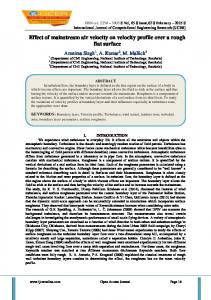
Fig. 1. Schematic representation of different spout fluidized bed contactors: (a) pseudo-2D, (b) rectangular, (c) slotted rectangular, and (d) cylindrical spout fluidized beds. The dotted arrows indicate the positions and angles of the background gas supply [16].
2. The total flow rate required to fluidize particles is lower in comparison to fluidized and spouted beds. This is mainly attributed to cross flow of additional background gas supply. Some of the key features of gas-spouted and gasfluidized beds are reported by Cui and Grace [14]. Spouted beds are primarily utilized for particulate materials which are coarser in size (usually having a mean particle diameters in excess of 1 mm) and narrower in particle size distribution than fluidized particles. In the recent years, computational fluid dynamics (CFD) studies have become popular in the field of gas–solid two phase flow [15–17]. The main advantage of a numerical simulation is that a wide range of flow properties may be obtained simultaneously. In previous study, [18] the effect of draft tube and its distance from the bed inlet at minimum fluidization velocity was studied. The results showed that the existence of draft tube decreases the minimum fluidization velocity and the increase of draft tube distance from the bed inlet increases this velocity. The draft tube insertion improves the bed performance by providing a restriction on the lateral particle flow. The aim of this study is to investigate the hydrodynamics of different spouted beds. In this work, CFD simulation of effect of geometry on flow regimes in different spout-fluidized bed is studied. Flow of gas and solids through the spout and annulus are analyzed and compared with measurements reported in the literature. Then minimum fluidization velocity for each case is calculated and related to the effect of geometry on flow regimes. Different geometries used in this study are shown in Fig. 1.
SIMULATION CONDITION Details of geometry and particle properties are shown in Table 1. Dc and Do are diameters of cylindrical and conical (or rectangular) part of the spouted bed and H0 is the height of bed. In this model triangle mesh with intervals of 1.5 has been used. Air velocity and atmospheric pressure are chosen as inlet and outlet boundary Conditions, respectively. Simulation of hydrodynamic fluidized bed is based on finite volume scheme, k–ε turbulence model. Simple pressure model has used for solving conservation equations. The results of Durate [19] have shown that Granular Eulerian Model can predict spouted bed dynamic. Therefore in this study a 3-D fluid dynamic simulation of spouted bed is calculated based on Granular Eulerian Model with the Gidaspow drag model. RESULT AND DISCUSSION Validation of model. In previous study [18], dynamic behavior of particles in a cylindrical spouted bed was studied and the Simulation results were compared with the experimental data and good agreement was obtained. Figure 2 shows diagram of particle radial velocity at different heights. Experimental data and results of simulation are shown at part (A) and (B) respectively. In these figures U is air velocity and Urms is minimum air inlet velocity. Experimental data are at U = 1.2 Urms. Cylindrical spout fluidized bed minimum fluidization velocity. The minimum spouting velocity is one of the important properties to study the hydrodynamic behavior of spouted and spout fluidized beds which is defined as the superficial gas velocity through the spout inlet at the inception of a spout, without consid-
THEORETICAL FOUNDATIONS OF CHEMICAL ENGINEERING
Vol. 51
No. 4
2017
510
SARA MORADI, SADEGH MORADI
ering particle movement in the annulus. This quantity can be determined by measuring the variation of pressure drop with superficial spout velocity. As the spout velocity increases, the pressure drop also increases linearly until it reaches a maximum value, after which it decreases dramatically up to a certain velocity and then remains constant. The value of the velocity at maximum pressure drop is known as the minimum spout velocity [13]. Minimum fluidization velocity can be calculated based on the volume fraction distribution comparison and by the following equation:
Minimum fluidization velocity Minimum air inlet velocity = . bed voidage In cylindrical spouted bed minimum air velocity was equal to 52.2 m/s [18] and the minimum fluidization velocity was calculated as below:
Minimum fluidization velocity = 52.2 = 82.86. 1 − 0.37 The experimental velocity for spouted bed without draft tube is 90 m/s [20]. The average deviation between the experimental and simulated velocities is 8%. This shows the validation of model.
Table 1. Parameters of the model geometry and particle properties Material
Soybean seed
ρs, kg/m3
1173
dp, mm
6
e, restitution coefficients
0.9
ε0, initial voidage
0.37
Dc, cm
21
Do, cm
3
H, cm
44
h, cm
16
H0, cm
25
Zhonghua et al. [21] have studied on CFD modeling of the gas–particle flow behavior in spouted beds. They observed that when the injected gas velocity is not high enough, a void is generated only in the lower region along the center axis. As the gas velocity is increased, the height of the void zone increases. The void finally reaches the freeboard at a certain gas velocity and a fountain is formed. Thus spouted bed has three regions; the spout, the fountain and the
(a)
(b) Particle velocity, m/s 7
Particle velocity, m/s 7
z = 0.118
6 6
U/Ums = 1.2 z, m
5 4 3
0.022 0.053 0.083 0.118 0.168 0.218 0.268 0.318
z = 0.168 z = 0.268 z = 0.318 4
z = 0.083
2
1
1
10 20 30 Radial distance from spout axis, mm
z = 0.053
3
2
0
z = 0.218
5
0
10 20 30 Radial distance from spout axis, mm
Fig. 2. Distribution of radial velocity: (a) experimental data [16] and (b) simulation results. THEORETICAL FOUNDATIONS OF CHEMICAL ENGINEERING
Vol. 51
No. 4
2017
3D SIMULATION OF EFFECT OF GEOMETRY ON MINIMUM FLUIDIZATION
(a)
(b)
511
(c)
6.29e–01 5.98e–01 5.67e–01 5.35e–01 5.04e–01 4.72e–01 4.41e–01 4.09e–01 3.78e–01 3.46e–01 3.15e–01 2.83e–01 2.52e–01 2.20e–01 1.89e–01 1.57e–01 1.26e–01 9.44e–02 6.29e–02 3.15e–02 0.00e+00
Fig. 3. Particle volume fraction distribution at different velocities: (a) 60, (b) 70, (c) 80 m/s.
annulus which can be observed when the gas velocity is increased further. Slotted Rectangular spout fluidized bed. In slotted rectangular spout fluidized bed a gas distributor, having a 60◦ inclination angle is used at the bottom of the bed. Figure 3 shows particle volume fraction distribution at different air velocities. As shown in Fig. 3 the minimum air velocity for fluidization of the bed is 70 m/s. According to previous section, the minimum fluidization velocity is calculated:
Minimum fluidization velocity = 70 = 111.11. 1 − 0.37 It is obvious that the minimum fluidization velocity has been increased in this situation. In relation to geometry influence, the slot-rectangular spouted bed will lead to higher values of product recovery and lower values of accumulated mass [22]. This occurred because the higher air drying velocity in slot-rectangular spouted bed caused increase in the particle motion inside the bed, increasing the attrition effect, contributing to the removal of the dried product from the spouted bed dryer. Similar behavior was obtained by Souza and Oliveira [23] in drying of herbal extract in a draft-tube spouted bed. Spouted beds of rectangular cross-section have been suggested as a means of eliminating the scale-up disadvantages of cylindrical-conical spouted beds [25, 26]. Passos et al. [26] and Kalwar et al. [25] suggested that the rectangular geometry could be scaled up without difficulty by simply increasing the column thickness for a given width. Freitas et al. [27] observed that spouting of solids in columns of large width/depth ratios requires higher air flowrates than conventional
cylindrical beds. This means that large width/depth ratios slot-rectangular spouted beds are unlikely to be suitable as an alternative to conventional cylindrical spouted beds. Kalwar et al. [28] claimed that the advantages of this configuration consisted in flexibility, simplicity of scale up by moving the facing vertical walls further apart and the ability to operate in direct–indirect mode for higher thermal efficiency in drying. Another advantage is visual studies of flow patterns. Rectangular spout fluidized bed. For this purpose a rectangular fluidized bed with 21 cm side and a square inlet with 3 cm side in the bottom has been used. Figure 4 shows particle volume fraction distribution at different air velocities in a rectangular spout fluidized bed. As shown in the Fig. 4 the minimum air velocity for fluidization of the bed is 45 m/s and the calculated minimum fluidization velocity is:
Minimum fluidization velocity = 45 = 71.43. 1 − 0.37 The minimum fluidization velocity in this case is lower than previous section. One could speculate that the dead zone in the rectangular bed contributes higher volume than the corresponding volume in a cylindrical bed, and therefore a higher flow rate is needed to achieve spouting than in a cylindrical bed of the same depth. However, the experimental data of literature [29] gives no indication that appreciably more flow is dissipated in the dead zone than in a cylindrical column. Flow characteristics in a rectangular spout-fluid bed were studied by Anabtawi et al. [30]. They observed rapid percolation of solid particles from the spout to the annulus for large flow rates when the bed
THEORETICAL FOUNDATIONS OF CHEMICAL ENGINEERING
Vol. 51
No. 4
2017
512
SARA MORADI, SADEGH MORADI
(a)
(b)
(c)
6.29e–01 5.98e–01 5.67e–01 5.35e–01 5.04e–01 4.72e–01 4.41e–01 4.09e–01 3.78e–01 3.46e–01 3.15e–01 2.83e–01 2.52e–01 2.20e–01 1.89e–01 1.57e–01 1.26e–01 9.44e–02 6.29e–02 3.15e–02 0.00e+00
Fig. 4. Particle volume fraction distribution at different velocities: (a) 40, (b) 45, (c) 50 m/s.
(a)
(b)
(c)
6.29e–01 5.98e–01 5.67e–01 5.35e–01 5.04e–01 4.72e–01 4.41e–01 4.09e–01 3.78e–01 3.46e–01 3.15e–01 2.83e–01 2.52e–01 2.20e–01 1.89e–01 1.57e–01 1.26e–01 9.44e–02 6.29e–02 3.15e–02 0.00e+00
Fig. 5. Particle volume fraction distribution at different velocities: (a) 40, (b) 43, (c) 50 m/s.
was spouted. Small jets of fluid were also observed in the annulus as a result of air percolation from the spout to the annulus. When the bed was in the minimum spout-fluidizing condition, an occasional eruption of a small fountain above the nozzle and in the spout region was observed; this lasted not more than 20s and then collapsed again. Anabtawi [29] has worked on effect of different parameters on Minimum spouting velocity for binary mixture of particles in rectangular spouted beds. He showed that the Minimum spouting velocity increases with the increase of the fraction of coarse particles in
the mixture until it eventually reaches that of mono disperse particle. The effect of the column diameter on Minimum spouting velocity in the cylindrical spouted beds was very limited. He also noticed that the deeper the bed and the closer to the maximum spoutable bed height, the longer time taken to achieve minimum spouting conditions. The effect of nozzle diameter on minimum spouting velocity for beds of mixed particles was studied. The results showed that the Minimum spouting velocity increases with the increasing of the nozzle diameter.
THEORETICAL FOUNDATIONS OF CHEMICAL ENGINEERING
Vol. 51
No. 4
2017
3D SIMULATION OF EFFECT OF GEOMETRY ON MINIMUM FLUIDIZATION
Van Buijtenen et al. [31] have worked on the effect of elevating the spout on the dynamics of a spout-fluidized bed, both numerically and experimentally. They showed that due to the elevation of the spout, the bubbles in the annulus remain undisturbed near the bottom of the bed and interact with the spout channel at a higher location depending on the spout height. It seems that the effect of spout elevation in the cylindrical 3-D bed is smaller compared with the rectangular fluidized bed. The bubbles in the annulus region are less affected as the spout elevates, causing the vortices in the annulus being less vertically stretched. Pseudo 2D spout fluidized bed. In experimental studies of fluidized beds, pseudo-2D fluidized beds (also referred to as 2D fluidized beds) are frequently encountered in literature [32]. These beds usually have a rectangular cross section. There is no strict guide line on how a pseudo-2D column should be designed. A general rule for constructing apseudo-2D fluidized bed is that the bed thickness should be less than the characteristic length of the flow i.e., bubble size, to facilitate better observation or imaging measurement [33]. A unique feature of a pseudo-2D system is its ability to facilitate the employment of non-intrusive visual or imaging techniques to directly observe and measure the complex inside flow movements. With this distinctive advantage, pseudo-2D systems have been widely used in fundamental fluidization studies, such as the studies of bubble properties, jet penetration, solids clustering, solids flow patterns, and solids mixing and segregation. A CFD simulation of a rectangular spout fluidized bed with a rectangular thin inlet tube was done. The height and side of inlet tube is 10 and 3 cm. Figure 5 shows particle volume fraction distribution at different air velocities in a pseudo-2D spout fluidized bed. The minimum air velocity for fluidization of the bed is 43 m/s and the calculated minimum fluidization velocity is:
Minimum fluidization velocity = 43 = 68.25. 1 − 0.37 The minimum fluidization velocity is lowest in this case. The existence of a thin rectangular tube in the entrance of fluidized bed increases the air velocity within the bed which leads to decreasing the minimum fluidization velocity required in the bed. Pseudo-2D setups are well suited to provide experimental data for validation purposes as it gives visual access to the main parts of the bed. Once a CFD model is validated for a pseudo-2D setup, it can also be used for practically more relevant systems like full 3D beds. A flow regime map was constructed by Sutkar et.al [7] for a flat bottom pseudo-2D spout fluidized bed with draft plates, by capturing high-speed images and Fast Fourier transformation (FFT) of measured pressure signals. In this study, eight distinct flow regimes
513
were identified by changing the background and the spout velocities. Increasing the spout and background velocities cause continuous particles transport with higher circulations rates through the fluidizing annulus. Moreover increasing the background velocity has a stabilizing effect on the particles in the annulus. CONCLUSIONS In this research, the influence of geometry on minimum fluidization velocity in a spout fluidized bed was investigated. Also the results and achievements of other literatures were reviewed. It was observed that pseudo-2D spout fluidized bed has the lowest minimum fluidization velocity because of its narrow rectangular tube and its usage is in experimental studies. After it, the rectangular spout fluidized bed has lowest velocity. The slotted-rectangular has the highest minimum fluidization velocity. Researcher showed that the slot-rectangular spouted bed will lead to higher values of product recovery and lower values of accumulated mass. Some literatures [30] say that the differences between the minimum spouting and minimum spout-fluidizing velocities in cylindrical and square beds are no greater than the differences between the predictions of various published correlations for cylindrical beds. One can therefore, recommend the use of rectangular beds as an alternative to cylindrical beds, because they are easier to construct and cheaper to manufacture. NOTATION Do
diameter of gas inlet, m
Dc
diameter of cylindrical part, m
d dp
diameter of draft tube, m particle diameter, m
H H0
cylindrical or rectangular height of spouted bed, m static height, m
h ρs
conical or rectangular height of spouted bed, m particle density, kg/m3
REFERENCES 1. Epstein, N. and Grace, J.R., Spouted and Spout-Fluid Beds: Fundamentals and Applications, New York: Cambridge Univ. Press, 2011. 2. Koppolu, L., Prasad, R., and Clements, L.D., Pyrolysis as a technique for separating heavy metals from hyper-accumulators. Part III: Pilot scale pyrolysis of synthetic hyper-accumulator biomass, Biomass Bioenergy, 2004, vol. 26, no. 5, p. 463. 3. Freitas, L.A.P., Dogan, O.M., Lim, C.J., Grace, J.R., and Luo, B., Hydrodynamics and stability of slot rectangular spouted beds. Part I: Thin bed, Chem. Eng. Commun., 2000, vol. 181, no. 1, p. 243.
THEORETICAL FOUNDATIONS OF CHEMICAL ENGINEERING
Vol. 51
No. 4
2017
514
SARA MORADI, SADEGH MORADI
4. Olazar, M., San José, M.J., Aguayo, A.T., Arandes, J.M., and Bilbao, J., Stable operation conditions for gas solid contact regimes in conical spouted beds, Ind. Eng. Chem. Res., 1992, vol. 31, no. 7, p. 1784. 5. Povrenović, D.S., Hadžismajlović, Dz.E., Grbavčić, Z.B., Vucović, D.V., and Littman, H., Minimum fluid flow rate, pressure drop and stability of a conical spouted bed, Can. J. Chem. Eng., 1992, vol. 70, no. 2, p. 216. 6. Bi, H.T., Macchi, A., Chaouki, J., and Legros, R., Minimum spouting velocity of conical spouted beds, Can. J. Chem. Eng., 1997, vol. 75, no. 2, p. 460. 7. Sutkar, V.S., van Hunsel, T.J.K., Deen, N.G., Salikov, V., Antonyuk, S., Heinrich, S., and Kuipers, J.A.M., Experimental investigations of a pseudo-2D spout fluidized bed with draft plates, Chem. Eng. Sci., 2013. vol. 102, p. 524. 8. Kalwar, M.I., Raghavan, G.S.V., and Mujumdar, A.S., Spouting of two-dimensional beds with draft plates, Can. J. Chem. Eng., 1992, vol. 70, no. 5, p. 887. 9. Kawaguchi, T., Sakamoto, M., Tanaka, T., and Tsuji, Y., Quasi-three-dimensional numerical simulation of spouted beds in cylinder, Powder Technol., 2000, vol. 109, no. 1, p. 3. 10. Takeuchi, S., Wang, S., and Rhodes, M., Discrete element simulation of a flat-bottomed spouted bed in the 3-D cylindrical coordinate system, Chem. Eng. Sci., 2004, vol. 59, no. 17, p. 3495. 11. Amsden, A.A. and Harlow, F.H., A simplified MAC technique for incompressible fluid flow calculations, J. Comput. Phys., 1970, vol. 6, no. 2, p. 322. 12. Chatterjee, A., Spout-fluid bed technique, Ind. Eng. Chem. Process Des. Dev., 1970, vol. 9, no. 2, p. 340. 13. Sutkar, S.V., Deen, N.G., and Kuipers, J.A.M., Spout fluidized beds: Recent advances in experimental and numerical studies, Chem. Eng. Sci., 2013, vol. 86, p. 124. 14. Cui, H. and Grace, J.R., Spouting of biomass particles: A review, Bioresour. Technol., 2008, vol. 99, no. 10, p. 4008. 15. Link, J., Zeilstra, C., Deen, N., and Kuipers, H., Validation of a discrete particle model in a 2D spout fluid bed using non intrusive optical measuring techniques, Can. J. Chem. Eng., 2004, vol. 82, no. 1, p. 30. 16. Zhou. H, Flamant.G, Gauthier.D, DEM-LES of coal combustion in a bubbling fluidized bed part 1: gas– solid turbulent flow structure, Chem. Eng. Sci., 2004, vol. 59, no. 20, p. 4193. 17. Du, W., Bao, X.J., Xu, J., and Wei, W.S., Computational fluid dynamics (CFD) modeling of spouted bed: Assessment of drag coefficient correlations, Chem. Eng. Sci., 2006, vol. 61, no. 12, p. 1401. 18. Moradi, S., Asadi, Z., Moradi, S., Salimi, M., Homami, S.S., and Seydei, M.K., Three-dimensional simulation of the effect of draft tube on minimum fluidization velocity in a spouted bed, Teor. Osn. Khim. Tekhnol., 2012, vol. 46, no. 5, p. 534.
19. Duarte, C.R., Neto, J.L.V., Lisboa, M.H., Santana, R.C., Barrozo, M.A.S., and Murata, V.V., Experimental study and simulation of mass distribution of the covering layer of soybean seeds coated in a spouted bed, Braz. J. Chem. Eng., 2004,vol. 21, no. 1, p. 59. 20. Duarte, C.R., Olazar, M., Murata, V.V., and Barrozo, M.A.S., Numerical simulation and experimental study of fluid–particle flows in a spouted bed, Powder Technol., 2009, vol. 188, no. 3, p.195. 21. Zhonghua, W. and Mujumdar, A.S., CFD modeling of the gas–particle flow behavior in spouted beds, Powder Technol., 2008, vol. 183, no. 2, p. 260. 22. Dotto, G.L., Souza, V.C., and Pinto, L.A.A., Drying of chitosan in a spouted bed: The influences of temperature and equipment geometry in powder quality, LWT—Food Sci. Technol., 2011, vol. 44, no. 8, p. 1786. 23. Souza, C.R.F. and Oliveira, W.P., Drying of herbal extract in a draft-tube spouted bed, Can. J. Chem. Eng., 2009, vol. 87, no. 2, p. 279. 24. Mujumdar, A.S., Raghavan, G.S.V., and Anderson, K., Characteristics of asymmetric two-dimensional slot spouted beds for grains, Drying 84, 1984, p. 205. 25. Kalwar, M.I., Raghavan, G.S.V., and Mujumdar, A.S., Circulation of particles in two-dimensional spouted beds with draft plates, Powder Technol., 1993, vol. 77, no. 3, p. 233. 26. Passos, M.L., Mujumdar, A.S., and Raghavan, V.S.G., Prediction of maximum spoutable bed height in twodimensional spouted beds, Powder Technol., 1993, vol. 74, no.2, p. 97. 27. Freitas, L.A.P., Dogan, O.M., Lim, C.J., Grace, J.R., and Luo, B., Hydrodynamics and stability of slot rectangular spouted beds. Part 1: Thin bed, Chem. Eng. Commun., 2000, vol. 181, no. 1, p. 243. 28. Kalwar, M.I., Raghavan, G.S.V., and Mujumdar, A.S., Spouting of two dimensional beds with draft plates, Can. J. Chem. Eng., 1992, vol. 70, no. 5, p. 887. 29. Anabtawi, M. Z., Minimum spouting velocity for binary mixture of particles in rectangular spouted beds, Can. J. Chem. Eng., 1998 vol. 76, no. 1, p. 132. 30. Anabtawi, M.Z., Uysal, B.Z., and Jumah, R.Y., Flow characteristics in a rectangular spout-fluid bed, Powder Technol., 1992, vol. 69, no. 3, p. 205. 31. van Buijtenen, M.S., Buist, K., Deen, N.G., Kuipers, J.A.M., Leadbeater, T., and Parker, D.J., Numerical and experimental study on spout elevation in spout-fluidized beds, AIChE J., 2011, vol. 58, no. 8, p. 2524. 32. Li,T. and Zhang, Y., A new model for two-dimensional numerical simulation of pseudo-2D gas–solids fluidized beds, Chem. Eng. Sci., 2013, vol. 102, p. 246. 33. Jin, Y., Zhu, J., Wang, Z., and Yu, Z., Fluidization Engineering Principle, Beijing: Tsinghua Univ. Press, 2001.
THEORETICAL FOUNDATIONS OF CHEMICAL ENGINEERING
Vol. 51
No. 4
2017