AUTHOR'S PROOF GeoInformatica (2006) 10: 529–548 DOI: 10.1007/s10707-006-0345-5
1 2
Specifying and Implementing Constraints in GIS—with Examples from a Geo-Virtual Reality System
4
Jildou Louwsma & Sisi Zlatanova & Ron van Lammeren & Peter van Oosterom
7 8
5
O O F
6
PR
Received: 10 February 2005 / Revised: 14 September 2005 / Accepted: 29 March 2006 # Springer Science + Business Media, LLC 2006
U
N
C
O
R
R
EC
TE
D
Abstract Constraints are important elements of every modelling process, but until now they have been treated in an ad hoc manner, depending on the specific application domain and the capabilities of the tools used. In GIS and GeoVR applications, constraints are conditions which always have to be valid (true) within the model populated with real geographic object instances. This paper argues that constraints should form a systematic part of the object class definition, similar to other aspects of the definition, viz. attributes, methods and relationships. Also, the implementation of constraints in all GIS and GeoVR subsystems (at front-end, database and exchange (I/O) level) should be derived automatically from the constraints specified by the framework. The paper therefore puts forward a framework for modelling constraints comprising (1) a classification and clarification of constraints, (2) a formal description using the unified modelling language/object constraint language (UML/OCL) and (3) implementation characteristics. The components of the framework are illustrated and applied to SALIX-2, a geo-virtual reality (GeoVR) landscape modelling system.
J. Louwsma
Q1 Waterschap Roer en Overmaas, Parklaan 10, 6131 KG Sittard, The Netherlands e-mail:
[email protected]
S. Zlatanova : P. van Oosterom Q1 GIS Technology Research Group, Delft University of Technology, Jaffalaan 9, 2628 BX Delft, The Netherlands
S. Zlatanova e-mail:
[email protected] P. van Oosterom e-mail:
[email protected] R. van Lammeren (*)
Q1 Centre for Geo-Information, Wageningen University, P. O. Box 47, 6700 AA Wageningen, The Netherlands e-mail:
[email protected]
9 10
13 14 15 16 17 18 19 20 21 22 23 24 25 26 27
AUTHOR'S PROOF 530
GeoInformatica (2006) 10: 529–548
28 29
1 Introduction
30
This paper discusses the important, but often underestimated, role of constraints when modelling geo-information and how to implement them in geographic information systems (GIS), in particular those extended to include Virtual Reality (VR) options, known as FGeoVR_. Constraints are conditions which must always be fulfilled by the user and the data processing functionality of the GeoVR application. So far, unfortunately, they have been treated in a very ad hoc manner, differing from one application to another, because of the lack of an adequate and extensive formal approach. They are very important in most applications, and some functions (e.g., linear programming in spatial decision support systems, least squares adjustment of survey data, cartographic generalisation) are based partially on constraints. However, they are not an integral part of a system development procedure, hence their specifications and implementation are often implicit, Fhidden_ in the application_s source code. It will therefore be very difficult to maintain constraints and constrained objects, especially if the user of the application interactively modifies the object constraints. This is true with respect to GIS in general, but in the interactive and dynamic environment of a GeoVR system the formalised support of constraints is even more essential. Throughout this paper we provide examples from a GeoVR system to illustrate the need for such formalisation and how it can be implemented. Certain types of constraints are already supported at present. Domain value constraints and referential integrity constraints in relational data base management systems (DBMS) [7] are standard functionality: e.g., whenever one object references another object via a foreign key the DBMS checks if the referenced object actually exists, in other words whether the primary key value occurs (otherwise the transaction/change will not be committed). Another example, specific to GIS applications, is support for topological constraints (e.g., certain types of objects must not overlap). Such topology constraints can be supported by the DBMS, based on either LaserScan Radius topology [14] or Oracle Spatial 10 g with topology [20]. They can also be supported at client/edit level, as in the ESRI ArcGIS [6] environment. Referential integrity and topological correctness are just two examples of the various constraint types, however. Constraints can be related to properties of the object itself, and they also can be based on relationships between two or more objects. Typical examples of a constraint relating to relationships between two objects are Fa Yucca tree must never stand in water_ and Fthe boss_s salary must always be higher than those of the other staff_. Constraints such as Fa tree must always be green_ or Fa staff member_s pay should be higher or equal to the minimum statutory pay_ illustrate constraints based on thematic properties of one object only. Such constraints need a formal description and definition. Constraints can be implemented at various levels (or subsystems) of an application, e.g., at front-end or user interface level (e.g., editing, simulation), at data exchange level and at database level. Currently, in geoVR systems, many constraints are implemented as object behaviour (and thus maintained in the
31 32 33 34 35 36 37 38 39 40 41 42 43 44 45 46 47 48 49 50 51 52 53 54 55 56 57 58 59 60 61 62 63 64 65 66 67 68 69 70 71 72 73
U
N
C
O
R
R
EC
TE
D
PR
O O F
Keywords object constraints . object constraint language . unified modelling language . virtual reality . GIS . GeoVR . 3D objects
AUTHOR'S PROOF GeoInformatica (2006) 10: 529–548
531
74 75 76 77 78 79 80 81 82 83 84 85 86 87 88 89 90 91 92 93 94 95 96 97 98 99 100 101 102
O
R
R
EC
TE
D
PR
O O F
application): for example, the constraint Ftwo trees (objects) cannot grow at the same location_ can be implemented (hard-coded in the editing environment) by means of collision detection, a well-known computer graphics technique. Despite the fact that support for constraints is still incomplete or fragmented in practice, there has been some research in this area. First of all, constraints have some relationship to issues such as data quality [11] and the stage and source of the errors [6]: data collection, data input, data storage, data manipulation, data output or use of results. Cockcroft [4] was one of the first researchers to put forward a taxonomy of such spatial integrity constraints. One of the things the current paper sets out to do is refine this taxonomy. Cockcroft [5] also argued that an integrated approach to handling integrity constraints entails developing a repository of data and constraints. The conclusion is that constraints should be part of the object class definition, like other aspects of the definition such as attributes, methods and relationships (generalisation/specialisation, part/whole and associations). The repository will be used by both the database and the application as a consistent source of integrity constraints. Here we continue these investigations into ways of managing constraints in an integrated system-wide manner and add the data exchange level as yet another part of the system where constraints are important. To this end we introduce a framework for object constraints based on the requirements of a GeoVR system for landscape modelling (SALIX-2). The paper is organised in six sections. Section 2 discusses the goal and current functionality of the SALIX-2 system as an illustration of an interactive GeoVR and explains why it needs to be extended to include constraints maintenance. Sections 3 and 4 develop a conceptual framework for classifying and formally defining constraints respectively. Section 5 discusses the implementation of constraints, focusing specifically on the DBMS. The last section discusses the results and makes suggestions for further research. It should be noted that much of the material put forward is still at the conceptual stage; full implementation is still work in progress, though important parts have been completed and proven to work.
C
2 Constraints in GeoVR: The SALIX system
U
N
Combining GIS with Virtual Reality produces GeoVR, where the spatial extent and object properties of the VR part are based upon data provided by the GIS part. The SALIX-2 system is a GeoVR system of this kind, enabling a user to interactively manipulate (e.g., import, delete, move) new objects (trees, bushes, etc.) in a 3D landscape at will and find out how the planting objects will grow. It is designed to provide a three-dimensional digital workspace for landscape architects and students [13]. For example, SALIX-2 (Figure 1) offers functionality for basing the location of planting objects regarding attributes (e.g., height), but this is not obligatory: in fact the user is free to locate the planting objects where he likes. SALIX-2 is also used to prototype and test new findings from geo-visualisation research at Wageningen University, in particular the GeoVR framework approach [1]. Using SALIX-2 in design studios provides information on the impact of VR facilities [10] on landscape architecture students_ progress in spatial thinking and reasoning. Examples of such VR facilities are F1:1 scale_ navigation, simulating growing processes on demand, alternating between architectural primitives and architectural objects, and quick transition between different views and projections.
103 104 105 106 107 108 109 110 111 112 113 114 115 116 117 118 119
AUTHOR'S PROOF 532
GeoInformatica (2006) 10: 529–548
D
PR
O O F
Fig. 1 3D scene in SALIX-2: an interactive landscape modelling system
U
N
C
O
R
R
EC
TE
During the design practicals it was found that students defined a brief, as the starting condition, and design rules during the design process. Both types of design constraints have to be satisfied by the results. As is the case in reality, these constraints are related to planting objects (trees, bushes) that have to fulfil conditions such as (1) being at a certain distance from one another (e.g., two trees have to be planted no closer than 3 metres to and no further than 6 metres from each other), (2) having to form other objects (e.g., a number of trees in a certain pattern together forming a hedgerow), or even (3) not being allowed to be planted in a given area (e.g., no trees on a road). As in a real world situation, a student should be restricted from planting on particular areas and objects: e.g., trees must not be planted in the middle of the road. The system therefore has to be explicitly provided with constraints relating to types of planting objects and geo-information objects which are well defined and can be maintained and changed easily through a formal procedure. Our proposed framework for object constraints identifies three different aspects: 1. classified and clarified constraints, 2. a formal description in a modelling language, 3. implementation at front-end, interface and database level (Figure 2). Depending on the type of constraints (and the application), some constraints can be best implemented at the front end (e.g., Edit, Move), others in the DBMS, and yet others in the exchange protocol. This paper focuses on the constraints to be implemented at database level by the DBMS. There are two reasons for this choice. The specifications of some constraints have to be easily accessible and intuitive to the user: these could be included in the object model, which needs to be as formal as possible. This makes it easier to update and change constraints. It also enables the user to be informed what kinds of constraints are available: for example, there could be a simple list of all the maintained constraints or a more sophisticated attempt-alert in the user interface. Secondly, DBMSs are based on SQL92, and since SQL92 the Fgeneral constraints_
120 121 122 123 124 125 126 127 128 129 130 131 132 133 134 135 136 137 138 139 140 141 142 143 144 145 146 147
AUTHOR'S PROOF GeoInformatica (2006) 10: 529–548
533
PR
O O F
Fig. 2 Constraints in GeoVR: front-end (right) specific, database (left) specific and exchange oriented (arrow)
148 149 150 151 152 153 154
R
R
EC
TE
D
(assertions) have been part of this standard, they could be used to implement the OCL constraints. Assertions are not supported in the DBMSs currently available; however, developers are referred to the use of triggers and procedures. Assertions may be considered as an intermediate step between UML/OCL and the actual implementation of constraints using triggers and procedures in the DBMS. The paper illustrates the implementation of constraints for SALIX-2 in a DBMS using triggers (see Section 5).
O
3 Classification of constraints
155 156 157 158 159 160 161 162 163
(1)
The number of objects/classes/instances involved. Constraints can be related to:
164 165
a single instance (restrictions on attributes and the relationship between attribute values of a single instance) two instances of same class (binary relationship) multiple instances of the same class (aggregate) two instances of two different classes (binary relationship) multiple instances of different classes (aggregate)
166 167 168 169 170 171
U
N
C
Classification of the different types of spatial etc. constraints reveals a complex taxonomy. Cockcroft [4] puts forward a two-dimensional taxonomy of these constraints, where the first axis represents the static versus transitional (dynamic) distinction and the second axis the classification into topological, semantic and user constraints. While we recognise that the transitional aspect of integrity constraints (allowed and valid operations) is relevant, in this paper we regard it as the other side of the same coin. We refine the second axis of Cockcroft_s taxonomy by recognising five sub-axes (different criteria) for the classification of integrity constraints:
& & & & &
AUTHOR'S PROOF 534
GeoInformatica (2006) 10: 529–548
(2)
The type of object properties and relationships between the objects involved: & & & & &
173 174 175 176 177
The dimension (related to the 2nd sub-axis): & & & &
spatial dimension (2D, 3D) temporal dimension mixed time and space, i.e., 4D thematic measurement scale The manner of expression:
& &
The nature of the constraint: & &
Ftheorem-based F (e.g., physically impossible: a tree cannot float in the air) Fdesign-based_ (e.g., bush should be south of tree)
D
(5)
Fmust never_ (a bush must never stand in water) or Fmust always_ (a tree must always be planted in open soil)
PR
(4)
178
O O F
(3)
metric (distance or angle between objects) topological (neighbourhood or containment) temporal thematic (semantic) complex: a combination of the above
172
N
C
O
R
R
EC
TE
In practice the way constraints are expressed is only important when it comes to communication between users. Once the object and the constraints have been formally defined, the expressions Fmust never_ and Fmust always_ can be represented by a single constraint, viz. the one that is more efficient from the implementation point of view: for example, the constraint Fa tree must never be in water, in the street or in a house_ is equivalent to the constraint Fa tree must always be in a garden or park_, assuming there are only five possible objects on the ground, water, street, house, garden and park. The second expression would seem to be more efficient, as it requires only two classes to be considered. Further elaboration will be given upon sub-axes 2 and 3, i.e., constraints with respect to object attributes and spatial relationships, and dimension.
U
3.1 Constraints derived from spatial etc. relationships between objects
179 180 181 182 183 184 185 186 187 188 189 190 191 192 193 194 195 196 197 198 199 200
The components of the proposed classification of integrity constraints based on relationships are as follows:
201 202
(1)
203
Spatial, with the following subtypes of relationship constraints: & & &
(2)
Direction: trees should be always south of paving polygons, so people can walk in the sunshine_. Topology: Fno trees or bushes inside water polygons; no trees or bushes inside paving polygons_. Distance: Fno trees in water, except if 1 metre from paving (so the leaves do not overlap with the paving)_.
204 205 206 207 208 209
Temporal: Fbushes may only be located after trees have been positioned_ (adjacent in time).
210 211
AUTHOR'S PROOF GeoInformatica (2006) 10: 529–548
535
212 213 214 215
The formalisation of such relationship constraints is closely related to that of spatial etc. associations between the objects. We suggest using the same mechanisms for defining constraints as for describing associations between objects. Direction constraints are based on the formalism for directional relationships [21]. A directional relationship is defined as the position of an object in relation to another object, and the directions can be stated as degrees in the range [0-, 360-] or as verbal expressions (Northeast, North, Northwest, West, Southwest, South, Southeast, East). The second approach is in fact a generalisation of the first one, since each expression stands for an interval in degrees. Algorithms can also be written to assign the correct direction to an object. Topological constraints are constructed using frameworks for neighbourhoods [8], [3]. The 9-intersection topology model, also recommended in the OGC/SFS standard, [17] utilises the fundamental notions of general topology for topological primitives to investigate the interactions of spatial objects. The basic criterion for distinguishing between different relationships is the detection of empty and nonempty intersections between the interior, exterior and boundary of objects. The maximum number of detectable relationships between two objects is 512 in theory, but only a small proportion of them are possible in reality. Eight relationships are given names, viz. disjoint, meet, contains, covers, inside, covered by, equal and overlap: for example, if the boundaries of the two objects intersect but the interiors do not, the conclusion is that the objects meet. The constraint Fno bush in water_ can be translated into Fno point-in-a-polygon_ (assuming a bush is represented as a point and water as a polygon), which corresponds to the topology relationship Fnot inside_. Distance constraints impose a constraint on a Euclidean distance between objects. They can be expressed in linear metres or by more approximate linguistic terms such as Fcloser than_, Ffurther than_ or Finterval distance_. Temporal constraints are specified on the basis of frameworks for describing temporal relationships between objects [22]. The temporal relationships between two time intervals are described in [12]. Given two time intervals, there are seven distinct ways in which they can be related (before, meets, overlaps, finishes, during, starts, equals). The relationships can relate to two time intervals or can be seen as existing between two objects with a certain time interval as the existence time (with the start and end time of existence marking the boundaries of the time interval). Thematic constraints are similar to the relationship constraints found in business logic for non-spatio-temporal systems. Finally, it is common to mix these fundamental types of relationship constraint. Specifying a certain density of objects in a certain area by quantity (or aggregate) constraints is only implicitly related to spatial relationships. Once the distribution of objects in a certain area is known, the minimum distance between two objects can be computed and, if appropriate, the approach for metric constraints can be used. From the user_s point of view, however, a more intuitive approach will be to specify a number per given area. This constraint can be stated as a minimum, exact or maximum number of objects related to a surface area (density). Examples of density constraints are the maximum number of houses in a residential area or the minimum number of trees there. Examples of
216 217 218 219 220 221 222 223 224 225 226 227 228 229 230 231 232 233 234 235 236 237 238 239 240 241 242 243 244 245 246 247 248 249 250 251 252 253 254 255 256 257 258 259
PR
D
TE
EC
R
R
O
C
N
U
(4)
O O F
Thematic (with semantics not related to spatial or temporal relationships): Fa parcel must always be owned by at least one person_. Mixed, e.g., quantity (or aggregate): Fmaximum of 10 planting objects in a specified area in the centre of the park_.
(3)
AUTHOR'S PROOF 536
GeoInformatica (2006) 10: 529–548
260 261 262 263
3.2 Constraints derived from properties of objects
264
In this category, constraints on the value of object properties (attributes), we can make a similar distinction as in the case of relationship constraints. We shall discuss the following three categories of property constraints: thematic (non-spatial business-logic-based), temporal, and spatial (area, perimeter, length). Thematic information about objects (with non-spatial temporal semantics) can be found in their attributes (e.g., house, road, grass). Some objects of the same type have relationships with objects of another type, e.g., all objects that are houses have a relationship with all objects that are roads. In interactive modelling, real-world thematic relationships between objects are used to formulate constraints that are understandable to the user, e.g., houses must be placed near roads so as to be accessible. The constraints in such cases are usually mixed with spatial constraints (e.g., Fnear_ in the example above). Temporal property constraints specify allowed values for one or more of the time attributes, e.g., the start time (birth) of an object must be before the end time (death) of that same object. Other temporal property constraints may specify valid values for time attributes, e.g., the date/time associated with a historic event must be in the past. Spatial constraints can be associated with spatial properties of an object such as size or shape. An example of a size constraint is Fa tree should not grow higher than 30 m_ and a constraint on shape could be Fa bush must be represented by an egg shape_.
265 266 267 268 269 270 271 272 273 274 275 276 277 278 279 280 281 282 283
3.3 Dimensional aspects of constraints
284
R
R
EC
TE
D
PR
O O F
exact number are one tower, three benches and one statue must be placed in this garden. This exact number of certain objects can be seen as a special case of a density constraint, as it can be defined as an exact number of certain objects for the whole area (i.e., the area in the 3D model).
285 286 287 288 289 290 291 292 293 294 295 296 297 298
3.4 Constraints selected for implementation in SALIX-2
299
The SALIX-2 system currently maintains three object classes, trees, bushes and ground surface. The possible ground surfaces are water, paving, soft paving, grass and bridge. The possible types of trees and bushes for use in planning are five
300 301 302
U
N
C
O
The last aspect to be discussed here relates to dimension. Generally speaking, all the different kinds of spatial relationship constraints can be specified for both 2D and 3D objects. Constraints can apply to the 2D ground plane or the 3D objects (bushes and trees) that could be placed on the ground plane to create a spatial configuration. The rules concerning the ground plane are based on the planning policy for a certain area and the fact that designations could conflict with one another. Policy makers lay down designations for each area and record them in plans. These designations for the ground plane can easily be stored as additional attributes of the separate polygons. The restrictions laid down by the policy makers could still conflict, however: e.g., a road can never be sited in water (except where a bridge or tunnel is built), a forest can never be sited on a major road and all houses should be accessible by a path or road. On the other hand, such conflicting constraints could also be a source of strategic spatial decision-making. The rules for 3D objects can even be more complex.
AUTHOR'S PROOF GeoInformatica (2006) 10: 529–548
537
303 304 305 306 307 308
4 Formal description of constraints
309
In the second part of the proposed framework, constraints have to be included in the object model, which should be as formal as possible so that constraint implementations can be derived within the various subsystems (Edit, Store, Exchange). Formal modelling is an essential part of every large project, but it is also very helpful in small and medium-size projects. A formal model enables ideas to be communicated with other professionals as well as providing a clear, unambiguous view of implementation strategies. Surveys have shown that large software projects have a high probability of failure if formal approaches are overlooked. Here we shall use Unified Modelling Language (UML), a standard for objectoriented modelling [18, Chapter 3] .UML is a graphic language which provides a wide range of ways of representing objects and their static and dynamic relationships. In general it can be used to model business processes, classes, objects and components, as well as for distribution and deployment modelling. UML consists of diagram elements (icons, 2D symbols, paths, strings), which can be used in nine different diagrams. The most appropriate diagram for describing static constraints is the class diagram, which provides a formalism for describing objects/classes (with their attributes and behaviour) and the relationships between these objects, such as association, generalisation and aggregation. Dynamics of objects (temporal constraints) can be modelled using one of the interaction diagrams, i.e., a sequence or collaboration diagram. While the former
310 311 312 313 314 315 316 317 318 319 320 321 322 323 324 325 326 327 328 329
O
R
R
EC
TE
D
PR
O O F
(CorAve, CorMAs, FraxExc, QueRob and RosCAn). Examples of rules for the positioning of objects in GeoVR environments are: Fa tree (object a) must not overlap with water (object b)_, and Fa tree (object a) must be covered by a polygon with the function Fforest_ (object b)_. For these constraints it makes sense to represent a tree as a circle (an extended object) rather than a point (a centroid). Table 1 shows some examples of constraints for SALIX-2.
t1.1
Type of relationship Direction Topology
Constraints with forced relationships between objects
t1.2
A bush must always be placed south of a tree (1 predicate) Bushes must always be disjoint or meet water (2 predicates) A bush must always meet or be disjoint with paved areas (also thematic constraint) (2 predicates) Trees must always be positioned >1 metre from paving (1 predicate) An oak always grows for 70 years (1 predicate) There must always be at least 10 trees on the specified ground surface (1 predicate) A bush must always meet or be disjoint with paved areas (note the mix topological constraint) (2 predicates) The distance between trees in water must always be >8 m and the distance between the tree and the edge of the water must always be ... post: result = ...
O O F
The context of an invariant is specified by the relevant class: e.g., Fparcel_ if the constraint was Fthe area of a parcel must be at least 5 m2_. It is also possible for a constraint to use an association between two classes (e.g., Fparcel_ must have at least one owner, which is an association with the class Fperson_). Below are two examples in UML/OCL syntax (keywords in bold print): context Parcel inv minimalArea: self.area > 5 context Parcel inv hasOwner: self.Owner -> notEmpty()
379 380 381 382 383 384 385 386 387 388 389 390 391 392 393 394 395 396 397 398 399 400 401 402 403 404
C
O
R
R
EC
TE
D
PR
The word Fself_ is used to specify the context and is omitted in many cases, as it is obvious what is meant by the constraint without this word. Figure 3 shows the UML class diagram with the objects and constraints (depicted as associations) used for SALIX-2 (as introduced in Section 2 and refined in Section 3, Table 1). In principle there is little difference between a Fdata model_ relationship (association, aggregation, specialisation) and a Fdata model_ integrity relationship constraint, both of which are depicted as lines in the UML class diagram. Normal associations are often indented in subsequent implementations so as to be explicitly stored (in one or both directions), however, whereas relationship constraints should not result in such storage (but in a consistency rule in the implementation environment). In order to distinguish between the two, normal relationships are depicted in black and integrity relationship constraints in colour. Notes (written in UML, OCL or natural language text) can be used in the diagram to explain the constraints on relationships and/or properties.
377 378
N
5 Implementation of constraints in the DBMS
U
The UML/OCL models managed in a repository should form the foundation for the user interface (e.g., Edit, Simulate) application environments, the storage data models (described in the DDLs of the DBMS) and the exchange data models. We shall not discuss the editing/simulation application environment here, apart from pointing out that it is very important to incorporate the integrity constraints from the model in these applications automatically. As regards data exchange, eXtensible Markup Language (XML) can be used for models containing the class descriptions at class level (XML schema document Fxsd_) and for data at object instance level (normal XML document with data Fxml_). XML documents also include the geometric aspect of objects (e.g., LandXML, GML, X3D). Here too more research is needed into the best way of incorporating integrity constraints in XML schemas. The UML models (inc. OCL) with constraints should be translated into XML schemas automatically. Note that this is different to encoding a UML model in an XML document using XML Metadata Interchange (XMI). In this section we
405 406 407 408 409 410 411 412 413 414 415 416 417 418 419
AUTHOR'S PROOF GeoInformatica (2006) 10: 529–548
U
N
C
O
R
R
EC
TE
D
PR
O O F
540
Fig. 3 UML class diagram representing the objects of interest in SALIX-2
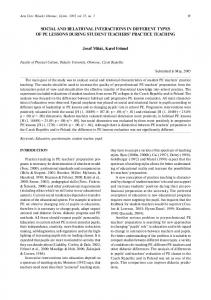
illustrate the implementation of integrity constraints with database examples, mainly because of the relatively high flexibility when it comes to specifying integrity constraints. The apparent benefit of front-end implementation is the direct interaction with the user (Figure 4). If a user places a planting object in the VRML scene, fast feedback on the validity of the placement can be provided if the constraints are also maintained in the visual environment (e.g., the VR component of the SALIX-2 system). Ways of changing constraints within the VR-environment are limited, however, as they are currently hard-coded in the VR application code, as they are in
420 421 422 423 424 425 426 427 428
AUTHOR'S PROOF GeoInformatica (2006) 10: 529–548
541
Users actions 1. select object type and behaviour
Java code
VRML browser
2. click ‘create’ button
3. activate VRML browser to click a place in the scene
3. callback 4. change button text from ‘create’ to ‘click place’
5. click place 6. get clicked location
7. add object
O O F
Database 8. convert local VRML coordinates to RD
Text output no
yes
9. show error message and the text: ‘click another place’
PR
triggers satisfied?
TE
D
9. insert into table_name 11. create VRML object
EC
10. transform coordinates
R
Fig. 4 Flowchart showing the interaction with the system SALIX-2 (with triggers)
U
N
C
O
R
many other editing/simulation environments (not managed centrally). In future development environments it should be possible to generate the part of the VR program application code that implements the constraints (as specified in UML/ OCL) automatically. Database implementation offers better management of constraints. If they are stored in a database, they are kept in a central place, easily accessible and therefore easily modifiable. As the VR application only connects to the database when saving or loading a planting plan (as with SALIX-2), however, there is no connection while the plan is being created (edited) interactively, so the user only receives feedback when the plan is saved, not when a planting object is placed. An obvious and simple improvement would be to connect to the database automatically after the user finishes a Flogical edit unit_. This would enable feedback to be provided immediately, generated by the database but displayed in the editing environment. The ideal solution would probably be for all subsystems to support integrity constraints (especially in disconnected scenarios), i.e., storing the constraints in a database at a central location and encapsulating this information in the application code. This would significantly improve feedback from the system. The constraints are stored more than once, however, which could result in inconsistency between the subsystems. It is very important, therefore, that the implementation of the constraints in the VR environment is derived automatically so as to guarantee consistency.
429 430 431 432 433 434 435 436 437 438 439 440 441 442 443 444 445 446 447 448 449
AUTHOR'S PROOF 542
GeoInformatica (2006) 10: 529–548
5.1 Assertions in SQL92
450
We now discuss the possibilities of implementation at DBMS level. There are two possible ways of implementing constraints, using assertions and triggers. The syntax of an assertion (Fgeneral constraint_) is as follows:
451 452 453
CREATE ASSERTION CHECK
454 455 456 457 458 459 460 461 462 463 464 465 466 467 468 469 470 471 472
create assertion constraint_1 check (not exists ( select * from prcv_treesrd_point t, prcv_gvkrd_poly g where t.treetype in (FCorAve_, FCorMas_, FRosCan_) AND g.descript = Fwater_ AND sdo_relate (g.geom., t.geom., Fmask=inside, querytype=window_) =_TRUE_))
473 474 475 476 477 478
C
O
R
R
EC
TE
D
PR
O O F
This syntax is quite simple and straightforward. When an attempt is made to commit the changes to a database, after a set of updates, inserts, and deletes, the assertion is checked: if the expression evaluates Ftrue_ the commit succeeds, otherwise it fails and the database remains in the old state (for which the expression was also Ftrue_). It is easy to imagine these assertions being generated automatically from the UML/ OCL invariants, similarly to the way database table definitions (DDL) can be derived from UML class diagrams. Assertions are supported in standard SQL92, [7] but unfortunately they have not yet been implemented in any of the mainstream DBMSs (Oracle, DB2, Ingres, Informix, PostgreSQL, MySQL). Assertions are compact representations of integrity constraints in the database, however, and therefore form convenient intermediate representations of their final implementations in the database. Let us now formulate a number of example constraints as assertions. The SALIX2 tables used in the assertions are: prcv_treesrd_point (planting objects of the type trees and bushes) and prcv_gvkrd_poly (ground surface with the description water, paving, soft_paving, grass and bridge). We shall use the examples introduced in Section 2 and refined in Section 3, Table 1 and illustrated in Section 4, Figure 3. Bushes must never be sited in water:
N
A bush must always be placed south of a tree:
U
(This assertion requires a geometry that represents the restricted area: the geometry must first be created, which can be done using a function. Here we use the name Ffu_restricted_area_ and the inputs to the function are two angles representing the direction and a maximum distance to restrict the search area. The function returns a geometry which has its basis in the location of the bush involved and can be used in the assertion.) create assertion constraint_2 check (exists ( SELECT * FROM prcv_treesrd_point t, prcv_treesrd_point b WHERE t.treetype IN (_FraxExc_, _QueRob_) AND b.treetype IN (FCorAve_, FCorMas_, FRosCan_) AND sdo_relate (t.geom, fu_restricted_area(first_angle, second_angle, distance, b.geom), _mask=ANYINTERACT, querytype=window_)=_TRUE_))
479 480 481 482 483 484 485 487 488 489 490 491 492 493
AUTHOR'S PROOF GeoInformatica (2006) 10: 529–548
543
Trees must always be positioned >1 metre from paving:
494
create assertion constraint_3 check (not exists ( SELECT * FROM prcv_treesrd_point t, prcv_gvkrd_poly g WHERE t.treetype IN (FFraxExc_, FQueRob_) AND g.descript IN (Fpaving_, Fsoft_paving_) AND sdo_within_distance (g.geom., t.geom., Fdistance=1_) =_TRUE_))
495 496 497 498 499
There must always be at least three trees on the specified ground surface. (this constraint uses the grass polygon with id 20).
500 501
PR
O O F
create assertion constraint_4 check ( ( SELECT count(t.treeid) FROM prcv_treesrd_point t, prcv_gvkrd_poly g WHERE t.treetype IN (FFraxExc_, FQueRob_) AND g.id=20 AND sdo_relate(t.geom, g.geom, Fmask=ANYINTERACT, querytype= window_)=_TRUE_) >=3) 5.2 Triggers and procedures
502 503 504 505 506 507 508 509 510 511 512 513 514 515 516 517 518 519 520 521 522 523 524 525 526 527
CREATE [OR REPLACE] TRIGGER BEFORE | AFTER INSERT OR UPDATE [] OR DELETE ON [FOR EACH ROW [WHEN (condition)]]
528 529 530 531 532
In order to avoid Flow-level_ hand-coding of constraints (or business rules) Oracle provides a development tool called Custom Development Method (CDM) that generates this code for the DBMS automatically [16], [2]. The CDM RuleFrame is
533 534 535
U
N
C
O
R
R
EC
TE
D
The assertions look nice and are relatively easy to specify, but as mentioned above, they are not supported in the mainstream DBMSs. Triggers therefore offer the only practical way of implementing constraints at present. These can be seen as small programs that check certain conditions and give an alert with respect to them. The same effect, basically, can be achieved using triggers as by defining assertions. One functionally correct, but not very efficient, way of implementing assertions would be to combine all the boolean expressions of the individual assertions into one big boolean expression. This would be checked on each commit to the database (via a trigger and procedure) and if the result is false, the transaction fails. This is not a very efficient implementation, however, and here we shall use triggers and procedures in a more specific way. The user has to develop the specific code for the triggers (and the procedures used) himself, however: while this is more labourintensive than specifying the higher-level assertions, it also provides additional functionality. Database triggers can be before triggers or after triggers, for example, and they can be row triggers or statement triggers. The order in which triggers are executed is critical to the DBMS. When there are two or more triggers of the same type the order in which they are executed is arbitrary. In the case of constraints it does not matter in what order they are checked, as they do not influence one another. The syntax for specifying a trigger is as follows:
AUTHOR'S PROOF 544
GeoInformatica (2006) 10: 529–548
536 537
a function that indicates when the rule should be validated a function that performs the actual validation, if the previous function indicates that this is necessary a handling procedure that manages communication with the outside world
538 539 540 541
CDM RuleFrame does not check business rules at the moment the user performs insert, update or delete statements; instead it stacks the rules that have to be enforced and checks them only at the moment of commit. This stacking of rules and any business rule enforcement is done in the Transaction Management component.
542 543 544 545
& & &
O O F
the CDM_s business rules implementation framework. The rules consist of three parts: [16]
5.3 Our implementation of constraints
U
N
C
O
R
R
EC
TE
D
PR
For the time being, and for the purpose of illustration, we decided to convert and hand-code our constraints in SALIX-2 and use the Oracle before and after triggers. One before each row trigger is sufficient to implement the constraints. First the temporary table is updated, then constraint checking takes place. A stored procedure is used for each constraint check. The disadvantage of using only one trigger for the constraint implementation is that the user cannot enable or disable separate constraints (as database triggers). Consequently the opportunities for interaction are rather limited in our current simple prototype implementation, but using only one trigger is less complex than using more than one. The constraint checking is organised as follows. For each insert or update statement relating to an object in the configuration table (with the trees and bushes that together form the planting plan) a before each row trigger is invoked. This first inserts all the new attribute values of the object involved in package variables. These attributes are easily accessible and can be used in all procedures and functions. All the procedures and functions are stored in a single package (named Fsalix_). A check takes place if the object involved is a bush (first bold line in Appendix); then all the constraints concerning bushes must be checked (using functions and procedures). If the object involved is a tree, the constraints concerning bushes are of no interest and all the constraints concerning trees must be checked (also using functions and procedures). In addition, all the constraints that cannot have the object involved as a starting point are checked in the after statement trigger (in our case, for example, the quantity constraint relates to a specific ground surface polygon). A partial example (Fa bush must not stand in water_) of a constraint implemented in a DBMS using triggers and procedures is shown in Box 1. In the front-end application a new object is created and an insert statement is sent to the DBMS. The statement is checked for integrity constraints (set of bold lines in Appendix) and feedback to the user is given through DBMS outputs. This output can be used by the front-end application. The constraint checking is done using triggers, packages, procedures and functions—all standard functionality in DBMSs. In the procedures more complex spatial etc. constraints can also be checked using PL/SQL, e.g., based on the operators available in Oracle spatial [19]. Further details of the implementation of concepts and a VR interface in SALIX-2 can be found in [15].
546 547 548 549 550 551 552 553 554 555 556 557 558 559 560 561 562 563 Q2 564 565 566 567 568 569 570 571 572 573 574 575 576 577 578 579
AUTHOR'S PROOF GeoInformatica (2006) 10: 529–548
545
580
6.1 Results obtained
581
Constraints have not received much attention in VR-GIS, despite the serious need for them, especially between objects. This paper proposes a classification of the constraint types relevant to a VR-GIS based on five aspects: 1. the number of objects/classes involved; 2. the properties of objects and/or relationships between objects: metric, topological, temporal, quantity, thematic or mixed; 3. the dimension (2D or 3D or mixed time and space, i.e., 4D); 4. the manner of expression Fmust never_ or Fmust always_; and 5. the nature of the constraint: theorem or designbased.. We analysed and defined a number of constraints for our SALIX-2 system, a VR-GIS simulator for landscape architecture. The formalisation of spatial etc. constraints must be specified in UML/OCL. The implementation of different parts of the system should be derived automatically from this single specification (in future, as current development environments are not capable of supporting this). The constraints should be implemented in the front end (to enable users to receive immediate feedback during editing), in the database (to ensure that only valid data is stored and accepted), and during communication or data exchange in the case of loosely coupled clients and servers (to ensure that the client is aware of the constraints). Database assertions do seem to be quite close to UML/OCL invariants, so it is rather disappointing that they are not yet available in mainstream DBMSs, where constraints currently have to be implemented using triggers (and procedures). This is the approach we adopted to implementing (handcoding) the different types of constraints for our SALIX-2 database.
582 583 584 585 586 587 588 589 590 591 592 593 594 595 596 597 598 599 600 601 602
6.2 Further research
603
R
EC
TE
D
PR
O O F
6 Conclusions
U
N
C
O
R
The first step should be to develop a good mechanism for checking whether the constraints specified (as part of the object descriptions) conflict with one another. This study only involved a check beforehand (in the conceptual phase). If users can change the constraint definitions once the application has been created, a conflict check should also take place when constraints are changed. This aspect is also of interest in the case of existing software: for example, topology constraints can be implemented in ESRI (geodatabase) software, [9] but there is no check on whether the constraints conflict with one another (neither beforehand nor while the software is running). This can result in unwanted system behaviour, e.g., Fan infinite loop_ correcting one error (according to rule 1) which results in another error (according to rule 2): there will never be a correct situation that satisfies both rules (integrity constraints). In real interactive applications an end-user, i.e., a non-programmer such as a landscape designer, must be able to change, delete or make new constraints, so a way of creating constraint definitions interactively is needed. This is closely related to modelling: cf. the UML class diagram with all the relevant object classes and their-restricted-relationships. The user should receive visual Ffeedback_ during editing, e.g., areas that turn red or green during an insert. These areas should be derived from constraints and the instance geometry in a DBMS based on spatial functionality (buffers, overlays, etc.).
604 605 606 607 608 609 610 611 612 613 614 615 616 617 618 619 620 621 622 623
AUTHOR'S PROOF 546
GeoInformatica (2006) 10: 529–548
624 625 626 627 628 629 630 631 632
Acknowledgment The authors would like to express their gratitude to Paul Strooper for checking and improving the English grammar and style, the four anonymous reviewers for their constructive remarks on an earlier version of this paper and the research programmes FSustainable Urban Areas_ at Delft University of Technology and FGeo-visualisation and communication_ at the Centre for Geo-Information, Wageningen University for making this publication possible.
633 634 635 636 637
Appendix
638
PR
O O F
Research is needed into whether these areas can be created in the DBMS (and presented as views) or using specific GIS software. This could be extended to 2 1/2D or 3D referenced objects, the objects of interest and their-interrelated-constraints. The objects of interest are currently limited to point objects (planting objects) and polygon objects (ground surfaces), but could be extended to include volume (polyhedron) objects. Data types and operations for 2 1/ 2D and 3D geometry—which are indispensable to implementing 2 1/2D and 3D constraints concerning 2 1/2D or 3D objects—are not yet available in DBMSs, however.
639
TE
D
1.1 Example PL/SQL code for triggers and procedures to implement constraints
U
N
C
O
R
R
EC
CREATE OR REPLACE TRIGGER brt_all_salix BEFORE INSERT ON prcv_treesrd_point FOR EACH ROW BEGIN – The treeid and the treetype of the object involved in the insert – statement are saved in a package. – These attributes can be used in the triggers, procedures and – functions. For the constraint checking in SALIX-2 they are – used to determine if the object is a tree or a bush and – only the corresponding constraints are checked pck_salix.treeid_io := :new.treeid; pck_salix.treetype_io := :new.treetype; END; CREATE OR REPLACE TRIGGER ast_salix AFTER INSERT ON prcv_treesrd_point BEGIN – constraint 1: a bush must never be placed in water; the existing – table with all objects has no bushes in water, so only – after each update or insert does a check have to take place if – the new location of a bush is in water. This can be – an after statement trigger. IF pck_salix.treetype_io IN (FCorMas_, FRosCan_, FCorAve_) THEN – the object is a bush, so all constraints concerning – bushes must be run. DBMS_OUTPUT.PUT_LINE(Fthe object involved is a bush_); pck_salix.pr_topology_c1; ELSE raise_application_error(-20099,Fthe object is a tree, no constraints have to be checked._); END IF; END;
t2.1 t2.2 t2.3 t2.4 Q3 t2.5 t2.6 t2.7 t2.8 t2.9 t1.11 t1.12 t1.13 t1.14 t1.15 t1.16 t1.17 t1.18 t1.19 t1.20 t1.21 t1.22 t1.23 t1.24 t1.25 t1.26 t1.27 t1.28 t1.29 t1.30 t1.31 t1.32 t1.33
AUTHOR'S PROOF GeoInformatica (2006) 10: 529–548
547
t1.34 t1.35 t1.36 t1.37 t1.38 t1.39 t1.40 t1.41 t1.42
CREATE OR REPLACE PACKAGE pck_salix IS treeid_io NUMBER; treetype_io varchar2(15); – procedure to check constraint 1: – a bush can never be placed in water procedure pr_topology_c1; END pck_salix;
t1.44 t1.45 t1.46 t1.47 t1.48 t1.49 t1.50 t1.51 t1.52 t1.53 t1.54 t1.55 t1.56 t1.57 t1.58 t1.59 t1.60 t1.61 t1.62 t1.63 t1.64 t1.65 t1.66 t1.67 t1.68 t1.69 t1.70 t1.71 t1.72 t1.73 t1.74 t1.75 t1.76 t1.77
U
N
C
O
R
R
EC
TE
D
PR
O O F
CREATE OR REPLACE PACKAGE BODY pck_salix AS – – procedure pr_topology_c1: a bush can never be placed in water – PROCEDURE pr_topology_c1 IS description varchar2(15); xrd_io number; yrd_io number; bush_in_water EXCEPTION; BEGIN SELECT g.descript, t.geom.sdo_point.x, t.geom.sdo_point.y INTO description, xrd_io, yrd_io FROM prcv_gvkrd_poly g, prcv_treesrd_point t WHERE t.treeid = pck_salix.treeid_io AND sdo_relate(g.geom, t.geom, _mask=anyinteract, querytype=window_) =FTRUE_ GROUP BY g.descript, t.geom.sdo_point.x, t.geom.sdo_point.y; IF description = Fwater_ THEN raise bush_in_water; ELSE DBMS_OUTPUT.PUT_LINE(F1: the bush is not placed in water_); END IF; EXCEPTION WHEN bush_in_water THEN raise_application_error (-20001, F1: The bush (x=F||to_char(xrd_io)||_, y=F||to_char(yrd_io)||_) is placed in water (a bush must never be placed in water). Place the bush at another location._) END pr_topology_cl; END;
References 1. M. Bloemmen, A. Ligtenberg, R. van Lammeren, T. Hoogerwerf. BApproaches for the use of geo-visualisation in participatory planning processes—version 7.^ PSPE project publication, Wageningen University, 2005, p. 26. 2. L.L. Boyd. BCDM RuleFrame—the business rule implementation framework that saves you work^. Oracle Corporation, iDevelopment Center of Excellence, ODTUG Business Rules Symposium, 2001. 3. E. Clementini, P. Di Felice, and P. van Oosterom. BA small set of formal topological relationships suitable for end-user interaction,^ in SSD_93 (Ed.), Third International Symposium on Large Spatial Databases, Singapore, LNCS No. 692, Springer: Berlin Heidelberg New York, 277–295, 1993.
641 642 643 644 645 646 647 648 Q4 649 650 651
AUTHOR'S PROOF 548
GeoInformatica (2006) 10: 529–548
U
N
C
O
R
R
EC
TE
D
PR
O O F
4. S. Cockcroft. BA taxonomy of spatial data integrity constraints,^ GeoInformatica, Vol. 1(4):327– 343, 1997. 5. S. Cockcroft. BThe design and implementation of a repository for the management of spatial data integrity constraints,^ GeoInformatica, Vol. 8(1):49–69, 2004. 6. F.C. Collins and J.L. Smith. BTaxonomy for error in GIS,^ in R.G. Congalton (Ed.), Proceedings of the International symposium on spatial accuracy in natural resource data bases, BUnlocking the Puzzle,^ American Society for Photogrammetry and Remote Sensing, Williamsburg, VA, pp. 1– 7, 1994. 7. C.J. Date and Hugh Darwen. A Guide to the SQL Standard. 4th edition, Chapter 14, AddisonWesley, 1997, pp. 197–218. 8. M.J. Egenhofer. BA formal definition of binary topological relationships^. In Proceedings of the 3rd International Conference on Foundation of Data Organisation and Algorithms, pp. 457–472, Paris, 1989. 9. ESRI. BWorking with the geodatabase: powerful multi-user editing and sophisticated data integrity^. ESRI white paper, February 2002. 10. M. Heim. Virtual Realism. Oxford University Press: New York, 1998. 11. G.J. Hunter. BManagement issues in GIS: Accuracy and Data Quality,^ in G.J. Hunter (Ed.), Proceedings: Conference on Managing Geographic Information Systems for Success, pp. 95–101, Aurisa: Melbourne, Australia, 1996. 12. Y-M. Kwon, E. Ferrari, and E. Bertino. BModelling spatio-temporal constraints for multimedia objects,^ Data & Knowledge Engineering, Vol. 30:217–238, 1999. 13. R. van Lammeren et al. BVirtual Reality in the landscape design process,^ in D. Ogrin, I. Marusic, and T. Simanic (EDs.), Landscape Planning in the Era of Globalisation, - [S.l.]: [s.n.], pp. 158–165, 2002. 14. Laser-Scan Technical Product Description—Topology Users Guide. Cambridge, UK, 2003. 15. J.H. Louwsma. BConstraints in geo-information models. Applied to geo-VR in landscape architecture^. MSc thesis in Geodetic Engineering, Delft University of Technology, 2004. 16. S. Muller. BCDM RuleFrame Overview: 6 reasons to get framed!^ Oracle Corporation, iDevelopment Center of Excellence, 2002. 17. OGC, Open GIS Consortium, Inc., BOpenGIS Simple Features Specification For SQL, Revision 1.1.^ OpenGIS Project Document 99-049, 1999. 18. OMG, Object Management Group. BUnified Modeling Language Specification (Action Semantics), UML 1.4 with action semantics,^ January 2002. 19. Oracle. BOracle 9i JDBC Developer_s Guide and Reference, release 2 (9.2),^ Part No. A9665401, March 2002. Chapter 3—Basic Features, Chapter 7—Accessing and Manipulating Oracle Data. 20. Oracle, BOracle Spatial Topology and Network Data Models, 10g Release 1 (10.1),^ 2003. 21. D. Papadias and Y. Theodoridis. BSpatial relations, minimum bounding rectangles and spatial data structures,^ International Journal of GIS, Vol. 11(2):111–138, 1997. 22. D.J. Peuquet. BIt_s about time: a conceptual framework for the representation of temporal dynamics in GIS,^ in W. Kuhn and P. Haunold (Eds.), Temporal Data in Geographic Information Systems, pp. 149–170, 1995.
652 Q4 653 654 655 656 657 658 659 660 661 662 663 664 665 666 667 668 669 670 671 672 673 674 675 676 677 678 679 680 681 682 683 684 685 686 687 688 Q4 689 690 691 692 693