Available online at www.sciencedirect.com
ScienceDirect Procedia Engineering 168 (2016) 1642 – 1645
30th Eurosensors Conference, EUROSENSORS 2016
A 2:1 MUX based on multiple MEMS resonators M. A. A. Hafiza*, L. Kosurub, M. I. Younisb and H. Fariborzia a
CEMSE Division, King Abdullah University of Science and Technology, Thuwal 23955-6900, KSA b PSE Division, King Abdullah University of Science and Technology, Thuwal 23955-6900, KSA
Abstract Micro/nano-electromechanical resonator based mechanical computing has recently attracted significant attention. This paper reports a realization of a 2:1 MUX, a concatenable digital logic element, based on electrothermal frequency tuning of electrically connected multiple arch resonators. Toward this, shallow arch shaped microresonators are electrically connected and their resonance frequencies are tuned based on an electrothermal frequency modulation scheme. This study demonstrates that by reconfiguring the same basic building block, the arch microresonator, complex logic circuits can be realized. © Published by Elsevier Ltd. This ©2016 2016The TheAuthors. Authors. Published by Elsevier Ltd.is an open access article under the CC BY-NC-ND license (http://creativecommons.org/licenses/by-nc-nd/4.0/). Peer-review under responsibility of the organizing committee of the 30th Eurosensors Conference. Peer-review under responsibility of the organizing committee of the 30th Eurosensors Conference Keywords: Mechanical computation, arch mems resonator, MUX, logic circuit
1. Introduction Recently, significant research has focused on the development of logic and memory devices based on MEMS/NEMS resonators [1]-[9]. Although there have been successful demonstrations of fundamental logic gates as well as multi-bit logic circuits, realization of more complex logic elements has remained elusive. Lately, we have demonstrated fundamental logic gates implemented with linear MEMS resonators [4]. First logic device realized based on dynamic response of a linear NEMS resonator [10] where the high (low) vibration amplitude of resonance denoted as 1(0). Later, a reprogrammable 2-bit logic device based on bistability of a nonlinearly resonating NEMS resonator capable of executing AND/NAND and OR/NOR logic functions was demonstrated [1]. Interconnect-free universal logic device capable of performing logic functions in parallel, and multibit complex logic operations realized based on the parametric excitation of a single electromechanical resonator [2]. * Corresponding author. Tel.: +0-000-000-0000 ; fax: +0-000-000-0000 . E-mail address:
[email protected]
1877-7058 © 2016 The Authors. Published by Elsevier Ltd. This is an open access article under the CC BY-NC-ND license
(http://creativecommons.org/licenses/by-nc-nd/4.0/). Peer-review under responsibility of the organizing committee of the 30th Eurosensors Conference
doi:10.1016/j.proeng.2016.11.480
M.A.A. Hafiz et al. / Procedia Engineering 168 (2016) 1642 – 1645
1643
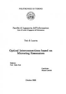
Despite all advances in this area of research, constructing complex logic functions has proven to be a formidable challenge. To address this problem, we demonstrate an alternative approach for construction of combinational logic circuits with MEMS resonators by reconfiguring the actuation and sensing circuits. Here we present a 2:1 MUX, a key logic element widely used as the building block of larger combinational logic circuits, based on electrically connected multiple resonators. 2. 2:1 MUX A digital MUX can select one binary input and then forward it into a single output channel, acting like a mechanical rotary switch. Fig. 1(a) shows a 2:1 MUX schematic that involves two data inputs, one select input, and one output. The selection depends on the binary state of the select input, which switches between the two input channels and forwards the selection to the output channel. As shown in its equivalent switching circuit in Fig. 1(b), the IN1 is directed to the output channel regardless of its binary state when the select input appears as 0. If the select input is 1, the directed input to output is taken from IN2, also regardless of its logic value.
Fig.1. 2:1 MUX: (a) Schematic (b) Switching circuit
2.1. Device structure We demonstrate here, a 2:1 MUX using two electrically connected microresonators. An SEM image of an arch microresonator is shown in Fig. 2(a). Microresonators are fabricated on the silicon device layer of a silicon on insulator (SOI) wafer. The fabrication process details have been described elsewhere [4]. Fig. 2(b) shows the pictorial top view of the experimental setup, which depicts drive electrodes, sense electrodes, and arch microbeam resonators (Res. X in blue, and Res. Y in Red). Res. X and Res. Y are placed in between nodes 1&2, and nodes 2&3, respectively. All the microbeams are biased with a single DC voltage source, VDC = 40V. The dimensions of the arch beams are as follows: Length=500µm, Width=3µm (Res. X), 1.5µm (Res. Y), and Thickness=30µm with a gap of 8µm between resonator and electrode. The initial curvature of the beam is 3µm. AC input signals are connected to the drive electrodes at node 4 and node 5 with respective switches, IN1, and IN2. This configuration then forms the inputs for the MUX, where logic input 1(0) is represented by the presence (absence) of an AC signal. Two sense electrodes are connected together at node 6, which forms the output of the MUX. Agilent Network analyzer is used to measure S21 transmission signal. A high (low) S21 transmission signal at on-resonance (off-resonance) state corresponds to logic output 1(0). A second DC voltage source, VT=0.49V is connected across node 1&3 with a switch, S. Switch ON (OFF) condition for switch S represents logic 1(0) state of the select input. Note that all the experiments have been conducted with the following preset conditions: pressure =1Torr, temperature=25 0C, VAC= (-) 15dBm (0.04Vrms), and fop=118.5 kHz.
Fig. 2. (a) SEM image of an arch microresonator, (b) experimental set-up
1644
M.A.A. Hafiz et al. / Procedia Engineering 168 (2016) 1642 – 1645
3. Results and discussions For the case of select input 0 (VT=0V), the resonance frequencies for Res. X and Res. Y are measured to be around 118.5 kHz and 106 kHz, respectively, Fig. 3(a). Upon changing the select input to 1 (VT=0.49V), a DC current flows through the microbeams. As a result, compressive stress is generated on the microbeam due to resistive heating. This results into increase in curvature and stiffness, hence, the resonance frequencies of Res. X and Res. Y are increased to 121.5 and 118.5 kHz, respectively, Fig. 3(a).
Fig. 3. (a) Resonance frequency vs. electrothermal voltage for Res. X and Res. Y, (b) frequency response at the output port, Out, for IN1=IN2=1.
Fig. 3(b) shows frequency responses of the microresonators sensed at node 6 for IN1=IN2=1. The black (red) line represents the case of select input 0 (1). It shows that at least one of the resonators will be at on-resonance state at fop=118.5 kHz, irrespective of the select switch state (1 or 0). Now, for IN1=1, IN2=0, and S=0, the Res. X is at onresonance state at 118.5 kHz. Hence, the output will show high (1) at fop=118.5 kHz. For IN1=1, IN2=0, and S=1, the output will show low (0) state. The corresponding switching diagram and time response is shown in Fig. 4(a). It clearly demonstrates that the state of IN1 is directed to the output, only for S=0.Next, for IN=0, IN2=1, and S=1, the Res. Y is at on-resonance state at 118.5 kHz, hence, the output will show high (1) for fop=118.5 kHz. And for IN1=0, IN2=1, and S=0, the output will show low (0) state. The corresponding switching diagram and time response is shown in Fig. 4(b). It also clearly demonstrates that the state of IN2 is directed to the output, only when S=1.
Fig. 4. Switching diagram and time response, (a) IN1=1, IN2=0, (b) IN1=0, IN2=1.
For IN=IN2=1 and S=0/1, either Res. X or Res. Y is at on-resonance state at 118.5 kHz. Hence, the output will always show high (1) for fop=118.5 kHz. The corresponding switching and time response is shown in Fig. 5(a). Note that due to a difference between the S21 signal levels at on-resonance states of Res. X and Res. Y, there is a little difference in the high states when the select switch is toggled between 0 and 1. However, for a well-defined threshold value for high (1) state, the successful logic operation can be achieved. Finally, for IN=IN2=0, none of the resonators will be actuated, hence, the output will always show low (0) state, irrespective of the select switch state (1/0). The corresponding switching diagram and time response is shown in Fig. 5(b).
M.A.A. Hafiz et al. / Procedia Engineering 168 (2016) 1642 – 1645
Fig. 5. Switching diagram and time response, (a) IN1=IN2=1, (b) IN1=IN2=0.
The truth table in Table 1 shows full agreement with that of a 2:1 MUX, as traditionally realized in solid state electronics. Table 1. Experimentally obtained truth table for the proposed 2:1 MUX
4. Conclusion In summary, we have demonstrated an alternative approach for construction of core digital logic element; 2:1 MUX based on multiple microresonators with a simple electrothermal frequency tuning scheme. Future directions in this research can be targeted to concatenate multiple MUXs to realize complex logic operations. The standard electrostatic transduction and CMOS friendly fabrication techniques used in this work naturally allow the systems to be compact and integrated on-chip. These practical demonstrations of digital logic elements on multiple MEMS resonators are promising steps towards achieving the ultimate goal of an electromechanical microcomputer. References [1]
D. N. Guerra, A. R. Bulsara, W.L. Ditto, S. Sinha, K. Murali, and P. Mohanty, “A noise assisted reprogrammable nanomechanical logic gate,” Nano Lett., vol. 10, pp. 1168–1171, 2010. [2] I. Mahboob, E. Flurin, K. Nishiguchi, A. Fujiwara, and H. Yamaguchi, “Interconnect-free parallel logic circuits in a single mechanical resonator,” Nat. Commun., vol. 2, p.198, 2011. [3] J. S. Wenzler, T. Dunn, T. Toffoli, and P. Mohanty, “A nanomechanical Fredkin gate,” Nano Lett., vol. 14, p. 89, 2014. [4] M. A. A. Hafiz, L. Kosuru, and M. I. Younis, “Microelectromechanical reprogrammable logic device,” Nat. Commun.,vol.7, p.11137, 2016. [5] R. L. Badzey, G. Zolfagharkhani, A. Gaidarzhy, and P. Mohanty, “A controllable nanomechanical memory element,” Appl. Phys. Lett., vol. 85, no. 16, pp. 3587–3589, Oct. 2004. [6] D. N. Guerra, M. Imboden, and P. Mohanty, “Electrostatically actuated silicon-based nanomechanical switch at room temperature,” Appl. Phys. Lett., vol. 93, no. 3, pp. 033515–33523, June. 2008. [7] H. Noh, S. B. Shim, M. Jung, Z. G. Khim, and J. Kim, “A mechanical memory with a dc modulation of nonlinear resonance,” Appl. Phys. Lett., vol. 97, no. 3, p. 033116, (2010). [8] W. J. Vestra, H. J. R. Westra, and H. S. J. van der Zant, “Mechanical stiffening, bistability and bit operation in a microcantilever,” Appl. Phys. Lett., vol. 97, p. 193107, 2010. [9] A. Uranga, J. Verd, E. Marigo, J. Giner, J. L. Munoz-Gamarra, and N. Narinol, “Exploitation of non-linearities in CMOS-NEMS electrostatic resonators for mechanical memories,” Sens. Actuators A, Phys., vol. 197, no. 1, pp. 88-95, Aug. 2013. [10] S. C. Masmanidis, R. B. Karabalin, I. De. Vlaminck, G. Borghs, M. R. Freeman, and M. L. Roukes, “Multifunctional nanomechanical systems via tunably coupled piezoelectric actuation,” Science, vol. 317, pp. 780-783, 2007.
1645