tored by the Army Intelligence Center under contract DABT63-96-C-. 0037. ... The Imagine architecture matches the demands of media .... These library calls.
To appear in Micro-31
A Bandwidth-Efficient Architecture for Media Processing
Scott Rixner1, William J. Dally, Ujval J. Kapasi, Brucek Khailany, Abelardo López-Lagunas, Peter R. Mattson, and John D. Owens Computer Systems Laboratory Stanford University Stanford, CA 94305 {rixner, billd, ujk, khailany, alopez, pmattson, jowens}@cva.stanford.edu Abstract
ture with a bandwidth-efficient register organization. Media applications are already a dominant consumer of computing cycles and are projected to account for over 90% of the cycles consumed by the year 2000 [2] [3] [6]. These applications, including rendering 2-D and 3-D graphics, image and audio compression and decompression, and image processing, operate on large streams of low-precision integer data and share three key characteristics. First, operations on one stream element are largely independent of the others. Thus, they can exploit large amounts of parallelism and tolerate large amounts of latency. Second, every stream element is read exactly once, resulting in poor cache performance. Finally, they are computationally intensive, often performing 100-200 arithmetic operations for each element read from memory. These applications are poorly matched to conventional architectures that cannot exploit the available parallelism, are optimized for low latency, depend on data reuse, and cannot support a high computation to memory access ratio. These applications are well matched, however, to the characteristics of modern VLSI technology. Modern VLSI computing systems are limited by communication bandwidth rather than arithmetic. In a contemporary 0.25µm CMOS technology, a 32-bit adder requires less than 0.25mm2 of chip area and a multiplier is smaller than 0.5mm2 of area.2 Hundreds of these arithmetic units fit on an inexpensive 1cm2 chip. The challenge is keeping these hungry units fed with instructions and data. It is infeasible to provide the data bandwidth required out of a global register file or the instruction bandwidth needed from a global issue unit. Locality is required to realize the potential of the technology. Fortunately, the streaming nature of media applications provides exactly the locality
Media applications are characterized by large amounts of available parallelism, little data reuse, and a high computation to memory access ratio. While these characteristics are poorly matched to conventional microprocessor architectures, they are a good fit for modern VLSI technology with its high arithmetic capacity but limited global bandwidth. The stream programming model, in which an application is coded as streams of data records passing through computation kernels, exposes both parallelism and locality in media applications that can be exploited by VLSI architectures. The Imagine architecture supports the stream programming model by providing a bandwidth hierarchy tailored to the demands of media applications. Compared to a conventional scalar processor, Imagine reduces the global register and memory bandwidth required by typical applications by factors of 13 and 21 respectively. This bandwidth efficiency enables a single chip Imagine processor to achieve a peak performance of 16.2GFLOPS (single-precision floating point) and sustained performance of up to 8.5GFLOPS on media processing kernels.
1. Introduction Application and technology trends together motivate a departure from the scalar, general-purpose register architecture in wide use today toward a stream-based architec1
Scott Rixner is an Electrical Engineering graduate student at the Massachusetts Institute of Technology. The research described in this paper was supported by the Defense Advanced Research Projects Agency under ARPA order E254 and monitored by the Army Intelligence Center under contract DABT63-96-C0037.
2
1
Based on area measurements taken from automatically generated layouts of actual arithmetic units.
needed. Forwarding streams of data from one processing kernel to the next localizes data communication and makes it easy to manage. Exploiting data parallelism allows a single instruction to be used by multiple arithmetic units and localizes data to a small cluster of units. The computational intensity of the applications can be exploited through instruction-level parallelism. Most importantly, it is easy to program a media application as a sequence of operations on streams of data in a manner that exposes the parallelism and locality required to execute the algorithm on a VLSI architecture. The Imagine architecture matches the demands of media applications to the capabilities of VLSI technology by supporting a stream-based programming model.3 Imagine is organized around a large (64KB) stream register file (SRF). Load and store operations move entire streams of data between memory and the SRF. To the programmer, Imagine is a load/store architecture for streams: one codes an application to load streams into the SRF, pass these streams through a number of computation kernels, and store the results back to memory. A stream computation, for example transforming triangle vertices, is performed by reading a stream from the SRF, passing its elements through a set of eight arithmetic clusters, and storing the results back into the SRF. Both data and instruction-level parallelism are exploited in a stream computation. The arithmetic clusters work in parallel on different elements of the stream and each cluster has several arithmetic units that operate under VLIW control on a single data element. Intermediate results during a computation are kept local to a cluster and do not use SRF bandwidth. This allows data bandwidth to be used efficiently in the sense that expensive, communication limited global register bandwidth is not wasted on the arithmetic units where inexpensive local bandwidth is easy to provide and use. Similarly, the recirculation of streams through the large SRF minimizes the use of scarce off-chip data bandwidth in favor of global register bandwidth. This is in contrast to conventional architectures which use less efficient global register bandwidth when local bandwidth would suffice, in turn forcing the use of more off-chip bandwidth. This paper introduces streams as a programming model and describes how the Imagine architecture uses a storage bandwidth hierarchy to exploit the parallelism and locality of streaming applications and achieve very high performance in a single-chip media processor. As described in Section 2, media applications are easily expressed as a sequence of computation kernels that operate on streams of data. Triangle rendering, for example, can be expressed as passing a stream of triangles through the stages of the tradi3
Memory
Arithmetic Clusters
Stream Register File
Memory Bandwidth
word
Register Bandwidth
record
Triangle Records 24 W
Input Data
Transform 108 ops
Triangle Records 24 W
Shade 513 ops
Shaded Triangle Records 15 W
Project/ Cull 171 ops
Projected Triangle Records 12 W
Span Setup 222 ops
Span Records 7W
Process Span 30 ops
Fragment Records 4W
Sort 20 ops
Fragment Records 4W Image Buffer Indices
Compact 10 ops
1W
Pixel Depth & Color 2W
Image Depth & Color
Pixel Depth & Color 2W
Z-Composite 3 ops
Pixel Depth & Color 2W
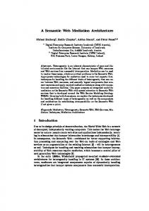
Figure 1: Stream-Based Triangle Rendering
tional graphics pipeline. The Imagine architecture, described in Section 3, provides a three-level storage hierarchy designed to support streaming applications. Programming of Imagine by writing a set of kernels that are then sequenced by application-level instructions is described in Section 4. The performance and bandwidth demands of applications are discussed in Section 5, and the stream architecture is compared to alternate architectures.
2. Stream Processing Media processing applications are easily expressed as a series of computation kernels that operate on large data streams. A kernel is a small program that is repeated for each successive element of its input streams to produce output streams for the next kernel in the application. Streams are organized as a sequence of records. Each record in a stream is a collection of related data words. Expressing a computation in the stream model enables a system to meet the large instruction and data bandwidth demands of media processing. The data bandwidth required by the kernels can be provided by a storage hierarchy optimized for streams, and the instruction bandwidth
The Cheops video processor [1] was also organized around the concept of streams, but with specialized function units and without the memory hierarchy of Imagine.
2
requirements are greatly reduced by exploiting data parallelism across the records of a stream. Figure 1 shows one way that triangle rendering [4], a representative media application, maps onto the stream processing model. Triangle rendering is composed of eight computation kernels that operate on data streams in succession. The input to the application is a stream of triangles used to represent objects. Each triangle in this stream is transformed into the viewing coordinate system, creating a new stream of triangles. This new stream is passed through the Phong shading kernel (although any shading algorithm could be used) to light the triangle vertices. This creates another stream, which is passed along to the next kernel, and so on, as depicted in Figure 1. The output of the application is the pixel color and depth information that is emitted from the z-composite kernel. As triangle streams are passed through the application, the image buffer will be the composition of all of the visible rendered pixels from those triangle streams. Ultimately, all of the objects’ triangles will have passed through the computation pipeline, and the image buffer will hold the final rendered image. The computation kernels themselves are expressed as compound stream operations. A compound stream operation is a small program that has access to the record at the head of each of its input streams and to its local variables. Explicit instructions read the input streams, so there is no need for the consumption rate of the input streams to be matched. Similarly, the tail of each output stream can be written explicitly at any point in the program. Since all streams are read and written independently, the length and record size of each stream can be different. These operations are compound in the sense that they perform multiple arithmetic operations on each stream element. This is in contrast to conventional vector (or stream) operations that perform a single operation on each element of the vector. Consider, for example, the first kernel in triangle rendering: model to world space transformation. For this transformation, there is only a single input and a single output stream. Both streams consist of 24 element triangle records, with the input triangles positioned in model space, and with the output triangles positioned in world space. Each triangle is composed of three vertices. A vertex contains eight 32-bit words: its three-dimensional coordinates in single precision floating point, a homogenous coordinate used for perspective, its rgb color packed into a single 32bit integer, and the normal vector for the vertex described by three coordinates in single precision floating point. The transformation computation can be expressed as a single compound stream operation, as shown in Figure 2. The outer loop is repeated for each 24 element triangle record in the input stream. Figure 1 also shows how triangle rendering maps onto a stream storage hierarchy. The storage hierarchy has three
loop over all triangles { loop over 3 vertices { // read vertex data from input stream [x, y, z, w, rgb, nx, ny, nz] = InputStream0; // tx ty tz
compute = r11 * = r21 * = r31 *
transformed x + r12 * y x + r22 * y x + r32 * y
// compute transformed tnx = n11 * nx + n12 * tny = n21 * nx + n22 * tnz = n31 * nx + n32 *
vertex coordinates + r13 * z + r14 * w; + r23 * z + r24 * w; + r33 * z + r34 * w; normal vector ny + n13 * nz; ny + n23 * nz; ny + n33 * nz;
// write vertex data to output stream OutputStream0 = [tx, ty, tz, w, rgb, tnx, tny, tnz]; } }
Figure 2: Transformation Kernel
components: the memory system, the stream register file, and local register files in the arithmetic clusters. The offchip memory holds persistent data. The SRF stores streams as they pass between computation kernels. The arithmetic clusters execute compound stream operations and contain local register files so that intermediate results do not need to recirculate through the stream register file. The triangle rendering computation begins by reading a stream of triangles from memory to the stream register file as shown in the upper left corner of Figure 1. The application then proceeds vertically down the figure by passing streams through successive computation kernels, as described earlier. During the course of these computations, streams are recirculated through the stream register file, and do not need to return to memory. Intermediate data within the kernels are held in local registers and thus do not consume stream register bandwidth. Finally, after processing by eight kernels, a stream of pixels is written from the stream register file back to memory. For each step, the number associated with each stream in the stream register file represents the number of words per data record, and the number associated with each kernel denotes the number of arithmetic operations performed by that kernel on each input record. For typical data (average triangles covering 25 pixels with a depth complexity of 5), rendering each triangle requires 1929 arithmetic operations, 666 SRF references, and 44 memory references. With a conventional microprocessor architecture, at least 5787 global register file references would be required (3 for each arithmetic operation). Thus, by capturing locality within the kernels, coding the application in the stream model reduces global register bandwidth demand by a factor of eight.
3. Imagine Stream Architecture Imagine is a programmable single-chip processor that supports the stream programming model. Imagine provides
3
SDRAM
SDRAM
SDRAM
SDRAM Memory Bandwidth
Host Processor
Host Interface
Network Interface
Stream Register File
Network
Streaming Memory System
ALU Cluster 7
ALU Cluster 6
ALU Cluster 5
ALU Cluster 4
ALU Cluster 3
ALU Cluster 2
ALU Cluster 1
MicroController
ALU Cluster 0
SRF Bandwidth
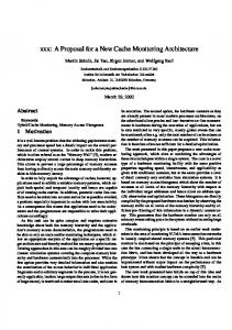
Imagine Stream Processor Figure 3: Block Diagram of Imagine
set shown in Figure 4. Load and store instructions move streams between the SRF and memory. These instructions take a stream descriptor that identifies a starting location, length, and record size of a stream in the SRF, and an address descriptor that provides the base address in memory and addressing mode (constant stride, indexed, or bitreversed). Send and receive instructions allow streams to be passed from the SRF of one Imagine to the SRF of another for multiprocessor applications. Finally, kernels are invoked by operate instructions. This instruction specifies the start address of the kernel in the control store of the microcontroller, stream descriptors for up to four source streams, and stream descriptors for up to four destination streams. For example, the triangle rendering application of Figure 1 is coded with just 11 application-level instructions. One load instruction reads the stream of triangles from memory. Seven operate instructions sequence the kernels from 75$16)250 to &203$&7. A load instruction uses the index vector computed by &203$&7 to read the old Z-values of the pixels in question. One more operate instruction initiates the =�&20326,7( kernel. Finally, a store instruction writes the visible pixels, and their Z-values, back to memory. Figure 3 shows a block diagram of the Imagine stream processor. The stream register file (SRF) is the nexus of the processor. The memory system, arithmetic clusters, host interface, microcontroller, and network interface all interact by transferring streams to and from the SRF. Kernel
a storage bandwidth hierarchy that corresponds to the three levels of Figure 1. Using this hierarchy to exploit the parallelism and locality of streaming media applications, Imagine is able to sustain performance of 8.5GFLOPS on key kernels. This is comparable to special purpose processors, yet Imagine is still easily programmable for a wide range of applications. Imagine is designed to fit on a 1cm2 0.25µm CMOS chip and to operate at 400MHz. Imagine is a coprocessor that is programmed at two levels: kernel and application. Kernels, like the triangle transformation kernel in Figure 2, are coded in a programming language using the expression syntax of the C language. Kernels may access local variables, read input streams, and write output streams, but may not make arbitrary memory references. As described in Section 4, kernels are compiled into microcode programs that sequence the units within the arithmetic clusters to carry out the kernel function on each stream element in turn. Load
Stream AddressDescriptor
Store
Stream AddressDescriptor
Send
Stream RoutingHeader Channel
Receive Stream Channel Operate Kernel IStream0..IStream3 OStream0..OStream3
Figure 4: Imagine Application-Level Instruction Set
At the application level, Imagine is programmed using C++ library calls on a host processor. These library calls pass instructions to Imagine using the stream instruction 4
+
+
+
*
*
/
To SRF
CU
intercluster network
Local Register File
cross point From SRF Figure 5: Imagine Cluster Organization
to be optimized for stream throughput, rather than the throughput of individual, independent accesses. The memory system provides 1.6GB/s of bandwidth to off-chip SDRAM storage via four independent 32-bit wide SDRAM banks operating at 100MHz.4 The system can perform two simultaneous stream memory transfers. To support these simultaneous transfers, four streams (two index streams and two data streams) connect the memory system to the SRF. Imagine addressing modes support sequential, constant stride, indexed (scatter/gather), and bit-reversed accesses on a record-by-record basis.
programs are loaded into the microcontroller’s control store by loading streams from the SRF.
3.1 Stream Register File (SRF) The SRF is a 64KB memory organized to handle streams. The SRF can hold any number of streams of any length. The only limitation is the actual size of the SRF. Streams are referenced using a stream descriptor, which includes a base address in the SRF, a stream length, and the record size of data elements in the stream. An array of 18 64-word stream buffers is used to allow read or write access to 18 stream clients simultaneously. The clients are the units which access streams out of the SRF, such as the memory system, network interface, and arithmetic clusters. The internal memory array is 32 words wide, allowing it to fill or drain half of one stream buffer each cycle, providing a total bandwidth of 51.2GB/s for all 18 streams. Each stream client may access its dedicated stream buffer every cycle if there is data available to be read or space available to be written. The eight stream buffers serving the clusters are accessed eight words at a time, one word per cluster, while the other ten stream buffers are accessed a single word at a time. The peak bandwidth of the stream buffers is therefore 74 words per cycle, or 118GB/s, allowing peak stream demand to exceed the SRF bandwidth during short transients. Stream buffers are bidirectional, but may only be used in a single direction for the duration of each logical stream transfer.
3.3 Cluster Array Eight arithmetic clusters, controlled by a single microcontroller, perform kernel computations on streams of data. Each cluster operates on one record of a stream so that eight records are processed simultaneously. As shown in Figure 5, each cluster includes three adders, two multipliers, one divide/square root unit, one 128-entry scratch-pad register file, and one intercluster communication unit. This mix of arithmetic units is well suited to our experimental kernels. However, the architectural concept is compatible with other mixes and types of arithmetic units within the clusters. Each input of every functional unit in the cluster is fed by a separate sixteen element local register file (LRF). These local register files store kernel constants, parameters, and local variables, reducing the required SRF bandwidth. Each cluster has 17 16-word LRFs for a total of 272 words per cluster and 2176 words across the eight clusters. Each local register file has one read port and one write port. The 17 local register files collectively provide 54.4 GB/s of peak data bandwidth per cluster, for a total bandwidth of 435.2 GB/s within the cluster array. In order to provide the equivalent bandwidth and storage needed within a cluster using a single register file, a
3.2 Memory System As described above, all Imagine memory references are made using stream load and store instructions that transfer an entire stream between memory and the SRF. This stream load/store architecture is similar in concept to the scalar load/store architecture of contemporary RISC processors. It simplifies programming and allows the memory system
4
5
The memory system architecture could also support Direct RDRAM.
across eight clusters, provide a peak computation rate of 16.2GOPS for both single precision floating point and 32bit integer arithmetic. The rate for byte operations is 64.2GOPS (the divider does not perform subword operations).
29-port, 256-entry register file would be required. This is significantly less efficient in terms of area and speed than the LRF organization. A simple storage cell for such a register file could be no less than 29 wiring tracks in both dimensions - one data wire and one control wire for each port. A more realistic storage cell would likely be much larger. An actual LRF storage cell is 6 wiring tracks by 8 wiring tracks. Therefore, the large multi-ported register file would require more than a 16x area increase over the 17 LRFs, making it the same size as three entire arithmetic clusters on Imagine. The LRF organization is also faster than a single multiported register file for two reasons. First, LRFs hold 16 words instead of 256 words. This leads to much less capacitive loading and faster register file accesses by at least a factor of two. Second, with a large multi-ported register file, read and write accesses each require one wire delay across a cluster. In modern VLSI, this global communication incurs a significant delay for every register file access. With the LRF structure, this wire delay is only incurred for writes, since the reads occur locally to each ALU. Additional storage is provided by a 128-word scratchpad register file, the second unit from the right in Figure 5. It can be indexed with a base address specified in the instruction word and an offset specified in a local register. The scratch-pad allows for coefficient storage, short arrays, small lookup tables, and some local register spilling. The intercluster communication unit, labelled &8 in the figure, allows data to be transferred among clusters over the intercluster network using arbitrary communication patterns. The communication units are useful for kernels such as the Fast Fourier Transform, where interaction is required between adjacent stream elements. The adders and multipliers are fully pipelined and perform single precision floating point arithmetic, 32-bit integer arithmetic, and 16-bit or 8-bit parallel subword integer operations, as found in MMX [9] and other multimedia extensions [8] [10]. The adders are also able to perform 32bit integer and parallel subword integer shift operations. All multiplication and floating point addition has a latency of four cycles, while logical operations and integer addition have latencies of one and two cycles respectively.5 The divide/square root unit is not pipelined and operates only on single precision floating point and 32-bit integers. The divider has a latency of 14 cycles for floating point divide, 13 cycles for floating point square root, and 21 cycles for integer divide.5 This gives a total of up to 21 arithmetic operations in flight for each cluster (168 for all eight clusters), half of which are utilized by key media processing kernels. The 48 total arithmetic units, six units replicated 5
3.4 Network Interface The network interface connects the SRF to four bidirectional links (400MB/s per link) that can be configured in an arbitrary topology to interconnect Imagine processors. A send instruction executed on the source Imagine processor reads a stream from the SRF and directs it onto one of the links and through the network as specified by a routing header. At the destination Imagine processor, a receive instruction directs the arriving stream into the SRF. The send and receive instructions both specify channels to allow a single node to discriminate between arriving messages. Using the stream model, it is easy to partition an application over multiple Imagine processors using the network. In the triangle rendering application of Figure 1, for example, higher throughput could be achieved by running the first three kernels on one Imagine, transmitting the output stream over the network to a second Imagine, and running the last five kernels on the second processor. The application is adapted by dividing the application-level code across the two processors, inserting a send instruction at one end, and inserting a receive instruction at the other.
3.5 Host Interface A host processor issues application-level instructions to Imagine with encoded dependency information. The host interface buffers these instructions in an instruction window and issues them when their resource requirements and dependency constraints are satisfied. The host interface allows an Imagine processor to be mapped into the host processor’s address space, so the host processor can read and write Imagine memory and can execute programs that issue the appropriate application-level instructions to the Imagine processor.
4. Programming Model Figure 6 shows the actual code for the triangle rendering application, as presented in Figure 1. This C++ program executes on the host processor and issues application-level instructions that direct Imagine to perform stream operations. A set of library functions provide an interface to the application-level instructions. The /2$'B0,&52&2'(� function loads the requested routine (e.g., 75$16)250�8&) if it is not already in the control store, and returns its starting
These latencies are derived from HSPICE simulations of the arithmetic units, including wiring parasitics extracted from the arithmetic unit layout.
6
void render_triangle_streams() { // Make sure the kernels are loaded into the Imagine microcontroller int transform = load_microcode(“transform.uc”); int shade = load_microcode(“shade.uc”); int project_cull = load_microcode(“project_cull.uc”); int span_setup = load_microcode(“span_setup.uc”); int process_span = load_microcode(“process_span.uc”); int sort = load_microcode(“sort.uc”); int compact = load_microcode(“compact.uc”); int z_composite = load_microcode(“z_composite.uc”); // Render a series of triangle streams for (int i=0; i