JOURNAL OF LATEX CLASS FILES, VOL. 6, NO. 1, MAY 2009
1
A Barycentric Vector Fitting Algorithm for Efficient Macromodeling of Linear Multiport Systems Dirk Deschrijver, Member, IEEE, Luc Knockaert, Senior Member, IEEE, and Tom Dhaene, Senior Member, IEEE
Abstract—Common-pole modeling of frequency responses can be time consuming for systems with highly resonant responses. This letter presents a Barycentric Vector Fitting algorithm that improves the running time of existing Vector Fitting algorithms. The effectiveness of the approach is demonstrated by applying it to coupled microstrip lines. Numerical results confirm the accuracy of the model and the savings in computation time. Index Terms—Macromodeling, Barycentric Interpolation, Vector Fitting, Transfer Functions, System Identification.
I. I NTRODUCTION ATIONAL modeling of frequency responses has received a lot of attention over the past decade. Such models are very important for efficient time domain and frequency domain simulation of microwave systems. When compared to other rational fitting methods, the Vector fitting (VF) algorithm was found to be a highly robust and efficient method, applicable to both smooth and sharply resonant responses of high order and wide frequency bands [1], [2]. Over the past decade, a lot of improvements to VF have been proposed. In [3], a fast QR step was proposed to reduce the computational complexity of the algorithm when fitting multi-port systems with many ports and poles. It was shown in [4] that also the convergence properties can be enhanced in the presence of noise by adding an additional relaxation constraint. This combined approach has become the de-facto standard algorithm, available on [5]. This letter presents a barycentric vector fitting algorithm that is able to compute models with comparable accuracy at a reduced computational cost. In particular, the computation time of the pole-identification step is reduced by exploiting the specific form of the barycentric interpolation formula. Numerical results confirm that this leads to significant savings in terms of computation time, while preserving a good accuracy. Another key difference with the existing VF algorithms is that the new approach does not require an a-priori choice of starting poles, which is often based on a heuristic procedure [1].
R
II. O UTLINE OF THE A LGORITHM The goal of the algorithm is to compute a macromodel that approximates all scattering elements Hv (s) (for v = 1, ..., V ) of a transfer matrix with a common set of P poles over a given frequency range of interest [smin , smax ]. All data samples are split in 2 disjoint sets S¯ and S, such that S¯ ∩ S = ϕ. K S¯ = {¯ sm , Hv (¯ sm )}M (1) m=1 , S = {sk , Hv (sk )}k=1 Manuscript received Jun 26 2012; revised Nov 7 2012. Authors are with Dept. of Information Technology, Ghent University-iMinds, Gent, Belgium (email:
[email protected]). D. Deschrijver is post-doctoral fellow of FWO-Vlaanderen. The work was supported by Interuniversity Attraction Poles Programme BESTCOM initiated by Belgian Science Policy Office
S¯ contains a small amount of M =P /2 samples that are equally spaced over the frequency range [6], whereas S comprises the K remaining data samples (usually K≫M). First, the algorithm computes a causal rational model that interpolates all data in S¯ (Sect. III). Then, the coefficients of this model are iteratively calculated such that the model also approximates the data S in a least-squares (LS) sense (Sect. IV). In each step of the iteration, the starting poles of the model are relocated to a better position. This process is called pole-identification. Once the accuracy of the model has converged or stalled, the iteration is terminated and the poles of the final model are found by solving an eigenvalue problem. Once these poles are calculated, all available data in S ∪ S¯ can be used to identify the corresponding residues as a linear LS problem, see [1]. III. R ATIONAL M ODEL R EPRESENTATION A. Barycentric Interpolation Formula A rational function Rv (s) that interpolates all the data in S¯ can be obtained by applying the barycentric interpolation formula. This formula yields an interpolating transfer function for any choice of non-zero barycentric weights (wm ̸= 0) [7] M ∑
Rv (s) =
Nv (s) = D(s)
wm Hv (¯ sm ) s − s¯m m=1 M ∑
(2)
wm w0 + s − s¯m m=1
Although (2) resembles the VF model representation, there are some differences: 1) both Nv (s) and D(s) share the same set of coefficients wm and 2) the common set of starting poles s¯m are purely imaginary instead of complex-valued. The starting poles s¯m are equally spaced over the frequency range (Sect. II) and located on the positive part of the imaginary axis. Unfortunately, the causality of model (2) is not guaranteed. B. Causal Model Representation As to obtain a real-rational causal model (Rv∗ (s)=Rv (s∗ )), both {¯ sm , Hv (¯ sm )} and {¯ s∗m , Hv∗ (¯ sm )} are interpolated and a linear combination of the basis functions is formed as shown in Appendix A of [1]. This modification leads to a transfer function with P = 2M complex conjugate, purely imaginary starting poles s¯ = {¯ sm , s¯∗m }M m=1 having real coefficients cp . P ∑
Rv (s) =
Nv (s) = D(s)
cp ΦN ¯) p,v (s, s
p=1
c0 +
P ∑ p=1
(3) c p ΦD ¯) p (s, s
JOURNAL OF LATEX CLASS FILES, VOL. 6, NO. 1, MAY 2009
2
The basis functions ΦN ¯) and ΦN ¯) are defined for p,v (s, s p+1,v (s, s each complex conjugate pole-pair {¯ sm , s¯∗m } of Nv (s) as ΦN ¯) = p,v (s, s ΦN ¯) = p+1,v (s, s
Hv (¯ sm ) Hv∗ (¯ sm ) + s − s¯m s − s¯∗m iHv (¯ sm ) iHv∗ (¯ sm ) − s − s¯m s − s¯∗m
(4) (5)
and similarly, ΦD ¯) and ΦD ¯) in D(s) are defined p (s, s p+1 (s, s for each complex conjugate pole-pair {¯ sm , s¯∗m } of D(s) as ΦD ¯) p (s, s
=
¯) ΦD p+1 (s, s
=
1 1 + s − s¯m s − s¯∗m i i − sk − s¯m sk − s¯∗m
(6) (7)
where p = 2m − 1 and m = 1, ..., M . Hence, for any choice of real-valued coefficients cp ̸= 0, the transfer function model ¯ Rv (s) in (3) will be causal and interpolates the data in S. IV. BARYCENTRIC V ECTOR F ITTING (B-VF) The flexible choice of coefficients cp allows one to impose extra properties to the model [8]. Here, coefficients cp are calculated iteratively such that the model also approximates the data in S in a LS sense. A linear formulation is obtained by multiplying both sides of (3) with D(s) and by minimizing: arg min cp
V ∑ K ∑
2
|Nv (sk ) − Hv (sk )D(sk )|
(8)
v=1 k=1
Hence, if the following definitions are introduced (c0 = 1), Hv′
= [Hv (s1 )...Hv (sK )]
(9)
diag([ℜe(Hv′ )
(10) (11)
ℑm(Hv′ )])
Hv = ˆ1 = (2K × 1) column vector of ones
then the coefficients cp of (3) can be calculated by solving the following overdetermined set of linear equations H1 ˆ 1 XvN −H1 X D XvN −H2 X D ˆ [C] = H2 1 (12) ... ... N D Xv −HV X HV ˆ 1 where the matrices XvN and XD are defined as follows [ ] [ ] ℜe(XvN ′ ) ℜe(X1D′ ) D XvN = , X = (13) ℑm(XvN ′ ) ℑm(X1D′ ) x Φ1,v (s1 , s¯) ... ΦxP,v (s1 , s¯) ... ... ... Xvx′ = (14) x x Φ1,v (sK , s¯) ... ΦP,v (sK , s¯) Here, x is a generic variable that denotes either N or D. Once the coefficients cp in solution vector C are found, one can simplify (3) by cancelling out the starting poles s¯. The relocated poles θ = {θ1 , ..., θP } of the transfer function are then the zeros of D(s). These zeros are calculated by solving an eigenvalue problem that is based on the minimal state space realization (A, B, C, D) of D(s), as shown in App. B of [1] θ = eig(A − BD−1 C)
(15)
The estimated poles can iteratively be refined by applying the Sanathanan-Koerner (SK) iteration with explicit weighting [2] 2 K (t) ∑ Nv (sk ) − H(sk )D(t) (sk ) arg min (16) (t) D(t−1) (sk ) cp k=1 So, instead of replacing the initial poles s¯ with the relocated poles θ, an inverse weighting function (1/D(t−1) (s)) is applied to each row of the LS matrix and updated values for the co(t) efficients cp are computed in each iteration step t = 1, ..., T . Once the accuracy of the model has converged, any unstable poles are flipped into the left half plane and the standard residue identification of VF is applied to compute a full LS ¯ see [1] for details. solution using all data in S ∪ S, V. R ELAXATION In order to improve the convergence properties of the SK iteration [9], the high frequency asymptotic constraint on D(t) (s)/D(t−1) (s) can be removed. This is achieved by making c0 a free variable, and adding an additional relaxation condition to the LS equations as shown in [4]. The implementation of relaxation [4] is completely analogous, and can easily be combined with the new presented methodology. VI. C OMPLEXITY A NALYSIS The computational complexity of the new algorithm can be analyzed by counting the number of floating point operations for the linear algebra problems that are involved. Following the same procedure as outlined in Sect. III of [10], it is shown that the number of flops for the QR-based VF algorithm is FlVF (V, K, M, P, T ) =
≃
T · [V · FlQR (2(K + M ), 2P ) +FlLSP (P V, P, 1) + Fleig (P )] +FlLSP (2(K + M ), P, V ) 16V KP 2 T
(17)
A similar analysis on the Barycentric VF algorithm shows that the number of flops can be further reduced by a constant factor FlB−VF (V, K, M, P, T ) = ≃
T · FlLSP (2KV, P, 1) + Fleig (P ) +FlLSP (2(K + M ), P, V ) 4V KP 2 T (18)
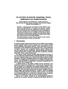
For both algorithms, the pole-identification step is the most expensive part. The VF algorithm performs a QR decomposition for each single matrix element (see (10) in [3]), and then it solves a compound least-squares problem (see (11) in [3]). The B-VF algorithm can reduce this cost because it only needs to solve a least-squares problem (12), albeit with a matrix on the left-hand-size that is somewhat taller in size. VII. N UMERICAL RESULT: C OUPLED M ICROSTRIP L INES This example demonstrates the modeling of a 6 inch coupled microstrip lines on an FR4 PC board [11]. The noisy Sparameters of the 4×4 transfer matrix were measured at 799 frequencies over the range [0.05 - 20 GHz]. They are modeled using the different modeling approaches outlined in Table I. A macromodel with P =100 poles was computed using B-RVF
JOURNAL OF LATEX CLASS FILES, VOL. 6, NO. 1, MAY 2009
3
0
10
Model Data Deviation
OVERVIEW Name QR-VF QR-RVF B-VF B-RVF
−1
Magnitude
10
−3
10
0
5
10 Frequency [GHz]
15
20
Response of model calculated with B-RVF (P = 100). x 10
QR−VF B−VF QR−RVF B−RVF
4.5
RMS Error
P 50 100 200 300 400 500
P 50 100 200 300 400 500
4 3.5
QR-VF 0.349 s 0.631 s 1.576 s 2.916 s 4.857 s 6.968 s
Gain 1.40× 1.56× 2.34× 2.72× 3.80× 4.33×
QR-VF 2.76 s 5.76 s 12.96 s 24.63 s 40.26 s 60.18 s
B-VF 1.38 s 3.58 s 7.94 s 12.77 s 17.71 s 22.36 s
Gain 1.99× 1.61× 1.63× 1.92× 2.27× 2.69×
C OMPUTATION TIME FOR
2.5
Algorithm QR-(R)VF
2
B-(R)VF
Fig. 2.
B-VF 0.248 s 0.404 s 0.671 s 1.069 s 1.276 s 1.606 s
QR-RVF 0.348 s 0.620 s 1.450 s 3.164 s 4.661 s 7.224 s
B-RVF 0.246 s 0.397 s 0.697 s 1.037 s 1.333 s 1.738 s
Gain 1.41× 1.56× 2.08× 3.05× 3.49× 4.15×
QR-RVF 2.96 s 5.56 s 14.10 s 25.46 s 39.61 s 59.85 s
B-RVF 1.57 s 3.76 s 8.26 s 13.08 s 18.07 s 22.74 s
Gain 1.88× 1.47× 1.70× 1.94× 2.19× 2.63×
TABLE IV
3
1.5 1
Description QR-based Vector Fitting QR-based Relaxed Vector Fitting Barycentric Vector Fitting (new) Barycentric Relaxed Vector Fitting (new)
TABLE III T OTAL C OMPUTATION TIME FOR MULTIPLE ELEMENT FITTING (V=16)
−3
5
TABLE I V ECTOR F ITTING A LGORITHMS
TABLE II T OTAL C OMPUTATION TIME FOR SINGLE ELEMENT FITTING (V=1)
−2
10
Fig. 1.
OF
2
3
4 Iteration count
5
6
POLE - IDENTIFICATION :
Pole Identification QR decompositions (10) in [3] LS matrix (11) in [3] LS matrix (12)
P=400 & V=16
Operations 272 Gflop 20 Gflop 61 Gflop
Time 19.25 s 1.42 s 7.95 s
7
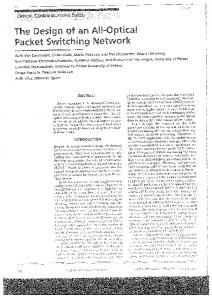
Evolution of RMS error in terms of iteration count t
and the result is shown in Fig. 1. In Fig. 2, the evolution of the RMS error is compared in terms of iteration count, and it is found that B-VF and B-RVF have a similar accuracy and convergence behavior as QR-VF and QR-RVF, respectively. In Tables II and III, also the total computation time is compared for the modeling of a single matrix element (V =1) or all the matrix elements (V =16). It turns out that the new barycentric algorithms are significantly faster, especially as the number of poles increases. Table IV shows that this speed-up is due to the faster pole identification step, as discussed in Sect. VI 1 . VIII. C ONCLUSIONS A fast approach for the macromodeling of frequency responses was presented. The method exploits the barycentric interpolation formula in order to speed-up the pole identification step. Numerical results show that the method delivers accurate results, even when the data is contaminated with noise. It improves the running time of QR-based VF algorithms, for the fitting of single/multiple elements of a transfer matrix. 1 All timing results are for T =10 iterations in MATLAB on 64-bit operating system with Intel(R) Core(TM) i7-2760 QM CPU at 2.4 GHz and 8 GB RAM. Timing results QR-VF and QR-RVF are based on implementation [5]. The starting poles are always chosen in an optimal way as discussed in [1], [2]
R EFERENCES [1] B. Gustavsen and A. Semlyen, “Rational approximation of frequency domain responses by vector fitting”, IEEE Trans. Power Del., vol. 14, no. 3, pp. 1052–1060, Jul. 1999. [2] D. Deschrijver, B. Gustavsen and T. Dhaene, “Advancements in iterative methods for rational approximation in the frequency domain”, IEEE Trans. Power Del., vol. 22, no. 3, pp. 1633–1642, Jul. 2007. [3] D. Deschrijver, M. Mrozowski, T. Dhaene and D. De Zutter, “Macromodeling of multiport systems using a fast implementation of the vector fitting method”, IEEE Microw. Wirel. Comp. Lett., vol. 18, no. 6, pp. 383-385, Jun. 2008. [4] B. Gustavsen, “Improving the pole relocating properties of vector fitting”, IEEE Trans. on Power Del., vol. 21, no. 3, pp. 1587-1592, Jul. 2006. [5] Public domain vectfit3.m software package, Vector Fitting website, http://www.energy.sintef.no/Produkt/VECTFIT/. [6] A. Semlyen and B. Gustavsen, “Vector Fitting by Pole Relocation for the State Equation Approximation of Nonrational Transfer Matrices”, Circ., Syst. and Sign. Proc., vol. 19, no. 6, pp. 549-566, 2000. [7] C. Schneider and W. Werner, “Some New Aspects of Rational Interpolation”, Math. of Comput., vol. 47, no. 175, pp. 285-299, Jul. 1986. [8] L. Knockaert, “A simple and accurate algorithm for Barycentric rational interpolation”, IEEE Signal Process. Lett., vol. 15, pp. 154–157, 2008. [9] C. Sanathanan and J. Koerner, “Transfer function synthesis as a ratio of two complex polynomials”, IEEE Trans. Autom. Contr., vol. AC-8, no. 1, pp. 56–58, Jan. 1963. [10] A. Chinea and S. Grivet-Talocia, “On the parallelization of vector fitting algorithm”, IEEE Trans. Comp. Pack. Manuf. Tech., vol. 1, no. 11, pp. 1761-1773, Nov. 2011. [11] W. Beyene and C. Yuan, “An Accurate Transient Analysis of High-Speed Package Interconnects Using Convolution Technique”, Analog Integr. Circuits and Sign. Processing, vol. 35, no. 2-3, pp. 107-120, 2003.