c(t) d(t). Acos(2Ïf0t) e(t) n(t) r(t) g(t) s(t) i(t). Channel. Transmitter bn i(tn+1). Receiver reset. Acos(2Ïf0t). 1. 2. VPP-PNS generator tn tn +1 tn+1. Data source. 2. 1.
A Chaos-based Direct-Sequence/Spread-Spectrum Communication Scheme Nguyen Xuan Quyen, Vu Van Yem, Thang Manh Hoang School of Electronics and Telecommunications, Hanoi University of Science and Technology, 1 Dai Co Viet, Hanoi, VIETNAM
Abstract—This paper proposes a novel direct sequence/spread spectrum (DS/SS) communication scheme, where bit duration is varied according to a chaotic behavior but always equal to a multiple of the fixed chip duration in the communication process. To recover exactly the data bits, the receiver needs an identical regeneration of both the pseudo-noise (PN) sequence and chaotic behavior.
I. P ROPOSED C OMMUNICATION S CHEME
Acos(2πf0t) Data source
d(t)
b(t)
p(t)
p(t) =
∞ ∑
PTc (t − tn ) ,
and its position is determined by the interval ⌋ ⌋ n ⌊ n ⌊ (k) ∑ ∑ Xk F (X0 ) tn − t0 = Tc = Tc ; m m k=1
g(t)
s(t) tn+1 tn reset p(t)
i(t)
i(tn+1)
bn
t n+1
c(t) 2 1 VPP-PNS generator
1 2 VPP-PNS generator Channel (a)
Receiver
reset m Clock generator fc =1/Tc
C(t) Tc X(t)
Xn-1
F(.)
1 p(t)
Xn
S/H (X0) start PN sequence generator
(1)
n=1
where the nth pulse is generated at the instance ⌊ ⌋ Xn tn = tn−1 + Nn−1 Tc = tn−1 + Tc , m
r(t)
c(t)
Transmitter
The pulse train at the output 1 is expressed as follows:
e(t)
∫ (.)dt
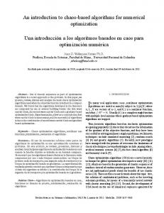
The proposed chaos-based DS/SS communication [1] scheme is presented in Fig. 1(a). Basically, the scheme is built around variable-position pulse and PN sequence (VPP-PNS) generator as in Fig. 1(b). A. VPP-PNS Generator
Acos(2πf0 t)
n(t)
2 c(t)
(b)
(2)
(3)
k=1
PTc (t) is the rectangular pulse shaping function given by { 1, 0 ≤ t ≤ Tc , PTc (t) = (4) 0, otherwise. With the initial instance t0 being fixed, Eq. 3 points out that this variation of position depends on the chaotic map F (.), initial value X0 and count-step m.
Fig. 1. (a) Proposed chaos-based DS/SS communication scheme, (b) Scheme for the VPP-PNS generator.
With a specific chaotic map F (.), in the iteration process, its output values vary chaotically in a defined range of [Xmin , Xmax ]. This leads to the variation of the bit duration within a defined time range of [Tbmin , Tbmax ] in the communication process. Since the chip duration Tc is fixed, the number of chips per each bit, Nn = Tbn /Tc , called the spreading factor, also varies in a defined range of [Nmin , Nmax ] which is determined based on Eq. 5 as follows: { Nmin = Tbmin /Tc = ⌊Xmin /m⌋ , (6) Nmax = Tbmax /Tc = ⌊Xmax /m⌋ . C. Receiver
B. Transmitter In the transmitter, each pulse of the train p(t) triggers the data source to shift the next bit to the output. It means that the nth bit is shifted at the instance tn and its bit duration is equal to the interval of [tn , tn+1 ]. Based on Eq. 2, the duration of the nth bit is determined by ⌋ ⌊ (n+1) ⌋ ⌊ F (X0 ) Xn+1 Tc = Tc . Tbn = tn+1 −tn = Nn Tc = m m (5)
III-1
The output signal i(t) of the integrator is reset to zero by the trigger of each pulse of the train p(t). Before each reset instance, the signal i(t) is sampled. The output value of the sampler at the instance tn+1 is determined by ∫ tn+1 ∫ Tbn (7) i(tn+1 ) = s(t)dt = s(t)dt. tn
0
Finally, the binary value of the data bit is recovered by the decision device based on the sign of the resulting sample.
D. BER Performance Bit error rate (BER) performance for the proposed communication scheme with the channel noise being additive white Gaussian noise (AWGN) is evaluated approximately as follows: N∑ max PN BERN , (8) BER = N =Nmin
where PN is the probability to the spreading factor being equal to N , and BERN is the BER of the scheme for case of the spreading factor being equal to N . Assume that the chaotic values distribute uniformly in [Xmin , Xmax ]. It means that the probability PN is the same for all values of N ∈ [Nmin , Nmax ], so we have PN = 1/(Nmax − Nmin + 1).
to exponentially increasing errors in the regeneration [3]. In this case, the detection of the variation of bit duration is completely incorrect, as a result, the BER is very high. This is proved by simulation results in Fig. 2. With only a very slight mismatch in the initial values (i.e., ∆X0 = 0.0001) between the transmitter and receiver, the BER performances for all four cases become the same and much worse than those of the no mismatch scheme. Although the ratio Ec /N0 increases gradually, the mismatch BERs are nearly unvaried and approximately equal to 1.6 10−1 . It is noted that the set of values of m, X0 and F (.) is considered as a secret key. It is impossible for the intruder to recover correctly the data without having full information on this secret key.
(9)
10
Based on the evaluation result of the error probability for the conventional DS/SS communication scheme with AWGN channel [2], the BERN is determined by [√ ] BERN = Q 2N (Ec /N0 ) , (10)
10
Conventional scheme Proposed scheme − Evaluation Proposed scheme − Simulation Proposed scheme − Initial value mismatch
−2
−3
[21, 41]
BER
here Ec is called the energy per chip, N0 is the noise power spectral density, Ec /N0 is known as the signal-to-noise ratio ∫ ∞ u2 (SNR) per chip, and the function Q[x] = √12π x e− 2 du. From Eqs. 8, 9, 10, the theoretical evaluation of the BER performance is given by the following equation: [√ ( )] N∑ max 1 Ec BER = 2N . Q (Nmax − Nmin + 1) N0 N =Nmin (11)
10
−1
10
−4
[26, 36]
10
−5
[48, 78] N=31
10
−6
[53, 73] N=63 −7
10 −13
−12
−11
−10
−9
−8
−7
−6
−5
−4
−3
E c /N0 (SNR per chip)
II. S IMULATION R ESULTS AND D ISCUSSIONS A numerical simulation for the proposed communication scheme with AWGN channel are carried out in Simulink for cases of [Nmin , Nmax ] = [26, 36], [21, 41], [53, 73], [48, 78]. Here, the nonlinear function used is tent map [3]. BER performances obtained from the simulation as well as the evaluation according to Eq. 11 are presented in Fig. 2. It can be seen that the simulation and evaluation results are nearly the same. The BER performances for cases having the same average spreading factor (i.e., Nav = (Nmin +Nmax )/2) are compared to each other and to that of the equivalent conventional scheme [2] which has a fixed spreading factor (N = Nav ). We can find that the proposed scheme with [26, 36] case performs slightly worse than the conventional scheme with (N = 31) and better than the [21, 41] case. Similarly, the performance of [53, 73] case is between that of the conventional scheme with (N = 63) and [48, 78] case. These comparison results point out a general rule is that the performance of the proposed system with [Nmin , Nmax ] gets better and approaches that of the corresponding conventional system with (N = Nav ) when both the values Nmin and Nmax tend closer to the value Nav and vice versa. Due to the sensitive dependence of the chaotic behavior on the initial value, a very slight error in its detection leads
III-2
Fig. 2. Evaluation and simulation BER performances of the proposed communication scheme for different cases of [Nmin , Nmax ] in comparison to those of the equivalent conventional scheme.
III. C ONCLUSION Analysis and simulation results point out that the proposed scheme not only still maintains an approximately good performance but also achieves a significant improvement of the information security compared to the equivalent conventional scheme. ACKNOWLEDGMENT This research is funded by Vietnam National Foundation for Science and Technology Development (NAFOSTED) under grant number 102.02-2012.34. R EFERENCES [1] F. C. M. Lau and C. K. Tse, Chaos-based Digital Communication Systems: Operating Principles, Analysis Methods, and Performance Evaluation, Springer, 2003. [2] R. L. Peterson, R. E. Zeimer, and D. E. Borth, Introduction to Spread Spectrum Communications, New York: Prentice-Hall, 1995. [3] R. C. Hilborn, Chaos and Nonlinear Dynamics: An Introduction for Scientists and Engineers, Oxford University Press, 2001.