Proceedings of the World Congress on Engineering 2012 Vol I WCE 2012, July 4 - 6, 2012, London, U.K.
A Combinatorial Application of Necklaces: Modeling Individual Link Failures in Parallel Network-on-Chip Interconnect Links Arseniy Vitkovskiy, Paul Christodoulides, Vassos Soteriou
Abstract— The advent of the multicore era [1, 2] has made the execution of more complex software applications more efficient and faster. On-chip communication among the processing cores, in the form of packetized messages, is managed with the use of on-chip networks (NoCs) [3]. Routers handling on-chip communication are point-to-point topologically interconnected using parallel links laid onto the silicon surface comprising a number of individual parallel wires. With the underlying interconnect structure becoming denser, due to improvements in CMOS technology, parallel links become susceptible to wear-out [4], with permanent link failures inhibiting communication completely and indefinitely. It is hence critical to explore their failure patterns in the wires comprising these links and hence build mechanisms which can recover corrupted in-transit data [5, 6]; since no real data from chip manufacturers exist, the derivation of a mathematical model in aiding the understanding of the distribution of individual wire faults in parallel on-chip links becomes mandatory. This paper takes the first steps in such direction. First it is shown how the given problem reduces to an equivalent combinatorial problem through partitions and necklaces. Then a model that counts certain classes of necklaces is derived by making a separation between periodic and aperiodic cases. The model is tested against a brute-force algorithm to prove its exactness. Finally the obtained model is used in finding the probability distribution of the size of the fault segment of wires in a parallel NoC-based multicore chip. Index Terms—Network-on-Chip, fault-tolerance, probability distribution, integer partition, necklace, combinatorics, modeling.
I
I. INTRODUCTION
N this article we derive and demonstrate the combinatorics-based models that can be used to calculate the spatial probability distribution of wire faults in a parallel Network-on-Chip (NoC) [3] interconnect link given its width (summation of the numbers of healthy and unhealthy1 wires in this parallel link), and a given number of faulty wires that can appear in this link. In previous studies [5, 6] that target the recovery of corrupted packetized data being re-transmitted through Partially Faulty Links (PFLs) it has been shown that the This work was supported in part by a startup research grant provided by the Cyprus University of Technology. All authors are with the Faculty of Engineering and Technology, Cyprus University of Technology, 3603 Limassol, Cyprus (e-mail:
[email protected]). 1 The terms “unhealthy”, “corrupted”, and “faulty” are used interchangeably throughout this article.
ISBN: 978-988-19251-3-8 ISSN: 2078-0958 (Print); ISSN: 2078-0966 (Online)
consecutiveness2 or “clustering” of these faulty wires directly determines the recovery latency required to restore received corrupted data among a pair of sender-receiver link-interconnected NoC routers. We are, therefore, particularly interested in the number of such consecutive faulty wires in a parallel NoC link as the “maximum wire fault clustering” directly determines the number of additional or overhead clock cycles that are required to retransmit a flit over a faulty parallel link that are necessary for data reconstruction and recovery at the downstream (receiver) router. To achieve this we derive a novel algorithm that can be used to determine the segmentation probability for an ordered collection of objects (i.e., parallel wires) of two distinct classes (faulty wires and healthy or “non-faulty” wires). The adjacent faulty wires form fault-segments (faulty wire clusters) separated by at least one healthy wire. As stated, the size of the largest segment determines the additional clock-cycle delay required by the Partially Faulty Link Recovery Mechanism (PFLRM) demonstrated in [5, 6] to recover corrupted flit3 data at a receiver router. We pay particular attention to the wire fault segmentation since the PFLRM mechanism is based on a flit data recovery scheme that utilizes a 1-bit circular rotation (per cycle of flit recovery) of the received flit vectors at the receiver router to extract and combine healthy bit portions from these corrupted received flit copies (at each cycle) with the rotated intermediate flit data results from the previous clock cycle(s) to eventually re-generate the flit in its healthy form downstream (the reader is urged to refer to [5, 6] for details). Hence, to be able to construct our faulty wire spatial distribution probabilistic model, the link comprised of parallel wires can be abstractly represented as a ring of parallel wires (since the rotational nature of the PFLRM mechanism virtually connects together the two wires found at the two ends of the parallel wire; refer to Fig. 1 for demonstration). We assume a random spatial distribution of faulty wires in the parallel NoC link, and aim to determine the probability distribution of corrupted (and noncorrupted) flit data bits. A flit is assumed to consist of a number of binary bits, equal to the width of the parallel link, i.e. each wire in the parallel NoC link carries one bit of data. To reach the goal of a complete mathematical model describing the probability distribution of the length of a fault-segment for a given number of wires and faulty wires 2 The terms “consecutive”, “clustering”, “adjacent”, and “segment(s)” are used interchangeably throughout this article. 3 A flit or “flow-control unit” is a logical segment of a packetized NoC message.
WCE 2012
Proceedings of the World Congress on Engineering 2012 Vol I WCE 2012, July 4 - 6, 2012, London, U.K.
we make use of a series of combinatorial arguments that include partitions and necklaces. Necklaces, apart from their intrinsic usefulness in the field of Combinatorics, have proven to be a powerful tool in other areas of Mathematics and other sciences. Some customary notions and theories related to necklaces include the Lyndon word [7], the actual homonym necklace problem (see, for example [8]), the necklace spitting problem [9], and most notably a proof of Fermat’s little theorem [10]. The rest of this article is organized as follows. In Section II the problem is formally defined. In Section III we explain the algorithm that leads to the determination of the probability distribution of the length of fault-segments for a given number of wires and faulty wires comprising a parallel NoC link, which is constructed through basic counting principles and probability rules, where appropriate, and through a derivation showing its correspondence to an equivalent necklace problem. In Section IV a series of results based on the derived model are presented, and then proven to coincide with the results of a brute-force algorithm implemented with the relevant Matlab software toolbox. In Section V an arithmetic example demonstrates the effectiveness of the obtained analytical model. Finally, Section VI concludes this article and sets future work directions with regard to the findings of this study. II. PROBLEM DEFINITION
T
HERE is a [parallel] NoC link consisting of W wires that are placed in parallel, wrapped around a common axis forming a ring shape (refer to Fig. 1). Each of these wires may be either healthy or faulty, and cannot possess both of these states. The number F and position (placement) of faulty wires are both random, where
0 ≤ F ≤ W.
Consecutively (adjacent) positioned faulty wires form a fault segment. Let S denote the size (or length) of the largest fault segment present in the link, where 0 ≤ S ≤ F . For given values of W and F , we seek to find the probability distribution of S , PW ( S | F ).
the construction of the algorithm through arithmetic examples that clarify all notions involved. A. Number of Possible Wire Arrangements Let A(W , F ) denote the set of all possible wire arrangements, for given W and F values. The cardinality (i.e., number of elements) of set A(W , F ) is simply equal to the number of combinations in choosing F faulty wires out of W wires, given by
⎛W ⎞ W! A(W , F ) = ⎜⎜ ⎟⎟ = . F F ! ( W − F )! ⎝ ⎠
(1)
Similarly, let A(W , F , S ) ⊂ A(W , F ) denote the set of all possible wire arrangements for given W , F and S values. Then, the problem reduces to finding A(W , F , S ) which when divided by A(W , F ) will yield exactly the required probability distribution PW ( S | F ). B. Initial Values As a first step, it is not difficult to see (using basic counting principles and probability rules) that for certain value choices of S and F , PW ( S | F ) can be obtained as follows
PW (0 | 0) = 1, PW (1 | 1) = 1, PW (W | W ) = 1, PW (W − 1 | W − 1) = 1,
⎛W ⎞ PW ( S | F ) = ( S + 1) ⎜⎜ ⎟⎟ ⎝F⎠ ⎛W − S − 2 ⎞ ⎟⎟ PW ( S | F ) = W ⎜⎜ ⎝ F −S ⎠
(if F = (W − F ) S ),
⎛W ⎞ (2) ⎜⎜ ⎟⎟ ⎝F ⎠ (if ⎡( F + 1) / 2⎤ ≤ S ≤ F ).
Thus, the task is reduced to finding the probability distribution PW ( S | F ) for all 0 < S < ⎡( F + 1) / 2⎤ , for given values of W and F . C. Size of Fault-Segment Let H denote the number of healthy wires in a parallel NoC link, i.e., H = W − F . From the problem definition, the size of the largest fault segment S has a lower bound which is equal to zero. However, it is possible to define the greatest lower bound of S more precisely (refer to Example 1 for demonstration) as
Fig. 1. An example of a parallel link (cross section) consisting of W = 8 wires with F = 4 faulty wires (shaded), where the largest fault-segment size is S = 2 (formed by the clustering of faulty wires 3 and 4). In reality, wires 1 and 8 are physically located at the two opposite ends of the parallel link.
H
III. ALGORITHM DESCRIPTION
EREAFTER we present an algorithm in order to find the probability PW ( S | F ) for each value of S for
given values of W and F . We find it useful to demonstrate ISBN: 978-988-19251-3-8 ISSN: 2078-0958 (Print); ISSN: 2078-0966 (Online)
⎡F / H ⎤ ≤ S ≤ F .
(3)
Example 1: Let W = 12 , F = 7. Then H = W − F = 5 and the greatest lower bound of S is ⎡F / H ⎤ = ⎡7 / 5⎤ = 2 ≤ S . Consequently for this case S can never be equal to 0 or 1. An illustration of such a wire arrangement is ××○××○×○×○×○, where the link is shown as an “unwrapped” transverse section, with ○ and × denoting a healthy and faulty wires, WCE 2012
Proceedings of the World Congress on Engineering 2012 Vol I WCE 2012, July 4 - 6, 2012, London, U.K.
respectively. The same link/wire representation is adopted throughput the remaining length of this article. D. Number of Fault-Segments Let σ denote the number of fault-segments in a parallel NoC link. It is not difficult to see (refer to the demonstration exhibited in Example 2) that
⎡F / S ⎤ ≤ σ ≤ min( F − S + 1, H ), S > 0.
(4)
Example 2: Let W = 12 , F = 7 and S = 4. Then,
σ min = ⎡F / S ⎤ = ⎡7 / 4⎤ = 2. Moreover, σ max = min( F − S + 1, H ) = min(4,5) = 4( = F − S + 1).
Such wire arrangements for σ = 2, 3 and 4, are respectively, the following: ××××○×××○○○○, ××××○××○×○○○, ××××○×○×○×○○, Now let S = 2 for the same W and F values. Then, σ min = ⎡F / S ⎤ = ⎡7 / 2⎤ = 4. Moreover,
σ max = min( F − S + 1, H ) = min(6,5) = 5( = H ). Such wire arrangement for σ = 4 and 5, are respectively, the following: ××○××○××○×○○, ××○××○×○×○×○. E. String Representation of Wire Arrangements Let a wire arrangement a ∈ A(W , F , S ) be represented by the string l = s1 s2 ...s H , where si is the size of the i th fault-segment followed by a single healthy wire. Making the convention that s1 = S , we have: H
∑s i =1
i
=F
( si ∈ Ζ 0+ ≤ S ,
s1 = S ).
(5)
Note that (5) allows si = 0, denoting an empty fault segment followed by a single healthy wire (refer to Example 3 below). Example 3: Let W = 12 , F = 6 and S = 2. Then H = W − F = 6. Clearly, one of the respective wire arrangements ××○○××○×○○×○ can be expressed by the string l = s1 s2 s3 s 4 s5 s6 = 202101 . The string representation for a wire arrangement, as described above, will allow us to count the actual number of wire arrangements. We now introduce some terminology that will help us to reach this goal. Definition 1: (a) The string l = s1 s2 ...s H is said to be periodic iff (i) H is a composite integer, and (ii) there exists t ∈ Ζ + such that si +t = si , ∀i ∈ Ζ + . We call t the period of string l. (b) If there is more than one t satisfying the condition (ii) above, then the string is said to have multiple periods that are all prime divisors of H , excluding 1 and H . (c) If condition (ii) is not satisfied, although the string l is non-periodic, for the sake of simplicity, the period is considered to be t = H . (d) The period t w of a wire arrangement a ∈ A(W , F , S ) ISBN: 978-988-19251-3-8 ISSN: 2078-0958 (Print); ISSN: 2078-0966 (Online)
that is represented by the string l of period t , can be obtained as follows. t
t
i =1
i =1
t w = ∑ ( si + 1) = ∑ si + t.
(6)
Example 4: As a demonstration of (6) consider the wire arrangement ××○×○××○×○ ∈ A(10,6,2) which has a period of t w = 5 (while the corresponding string s1 s2 s3 s4 = 2121 is of period t = 2 ). Definition 2: The frequency f of string l = s1 s 2 ...s H is the number of occurrences of a repeating substring lt = s1 s2 ...st within l , where t is the period of l , and is given by
f = H / t.
(7)
Clearly, if string l has multiple periods, hence it has multiple frequencies as well. Definition 3: The frequency f w of the wire arrangement a ∈ A(W , F , S ) is the number of occurrences of a repeating sub-arrangement at within a, where t w is the period of a, w and it is given by
f w = W / tw .
(8)
Clearly, using (6), (7), and (8) and Definition 2, the respective frequencies f w and f of the wire arrangement a ∈ A(W , F , S ) and the corresponding string l are equal. Note here that, due to the convention in the definition of string l above (refer to (5)), one string l corresponds to t w equivalent rotations of wire arrangements (refer to Example 5). If string l is non-periodic, i.e. t = H , then, by (5), the number of equivalent rotations of wire arrangements is t
t w = ∑ si + t = F + H = W .
(9)
i =1
Example 5: Let W = 8, F = 4 , and S = 2 . Then H = 4. A non-periodic string l = 2200 corresponds to t w = W = 8 equivalent rotations of wire arrangements, demonstrated as follows: ××○××○○○, ○××○××○○, ○○××○××○, ○○○××○××, ×○○○××○×, ××○○○××○, ○××○○○××, ×○××○○○×. However the periodic string l = 2020 corresponds to only t w = s1 + s2 + t = 2 + 0 + 2 = 4 equivalent rotations of wire arrangements: ××○○××○○, ○××○○××○, ○○××○○××, ×○○××○○×. Clearly, with the introduction of the notion of the string as explained above has reduced the presented problem to finding all possible strings l with non-intersecting sets of equivalent rotations of wire arrangements.
WCE 2012
Proceedings of the World Congress on Engineering 2012 Vol I WCE 2012, July 4 - 6, 2012, London, U.K.
F. Partitioning of the Number of Faulty Wires and Corresponding Necklaces We use integer partitions in order to find all string representations of all wire arrangements. Definition 4: A k-partition p of a positive integer n is a partition consisting of exactly k terms, adding zeros whenever necessary. Returning to the presented problem for a parallel link arrangement of W wires, with F faulty wires and a largest fault segment S , an H -partition p of (integer) F consists of H (number of healthy wires) terms, with the largest term being equal to S (refer to Example 6). Example 6: Let W = 18, F = 12 and S = 3. Then H = 6 . The 6-partitions of F = 12 , with the largest term being equal to S = 3 , are given as follows:
3+ 3+ 3+ 3+ 0 + 0, 3+ 3+ 3+ 2 +1+ 0, 3 + 3 + 3 + 1 + 1 + 1, 3 + 3 + 2 + 2 + 2 + 0 , 3 + 3 + 2 + 2 + 1 + 1, 3 + 2 + 2 + 2 + 2 + 1 . Clearly there is no 1-1 correspondence between the 6partitions above with the strings l of the wire arrangements. For instance p = 3 + 3 + 3 + 3 + 0 + 0 corresponds to a set of strings, namely 333300, 333030, 333003, and so forth. Hence, still, knowing the actual H partitions corresponding to given W , F and S does not solve the problem, as the number of strings per partition must be found. This can be achieved by noting that the number of all possible strings l with non-intersecting sets of equivalent rotations of wire arrangements can be represented by the number of necklaces of each H -partition (refer to Example 7 for illustration). We recall the definition of a necklace as follows. Definition 5: A k-ary necklace of length n is an equivalence class of n-character strings over an alphabet of size k, taking all rotations as equivalent [11]. Example 7: Let W = 6 , F = 3 and S = 2 . Then H = 3. It turns out that there is only one 3-partition of F = 3 , with the largest term being equal to S = 2 , namely 2 +1+ 0. All necklaces for the 3-partition above, with the corresponding equivalent rotations of wire arrangements, are 210 : ××○×○○, ○××○×○, ○○××○×, ×○○××○, ○×○○××, ×○×○○×. 201 : ××○○×○, ○××○○×, ×○××○○, ○×○××○, ○○×○××, ×○○×○×. Note that there is a 1-1 correspondence between the necklaces above and (all possible, for this case) strings l , whose corresponding sets of equivalent rotations of wire arrangements do not intersect. For each H -partition one can compute the corresponding number of necklaces (refer to (11)), which in turn can be used to compute the number of wire arrangements. Hence, the problem reduces to finding: (a) all such H -partitions, as described above, and subsequently, (b) their corresponding number of necklaces.
generate such a list of H -partitions in a constant amortized time [12]. Note here that a partition can be extended to an H -partition by simply adding the necessary number of zeros. However, we use an alternative and simpler approach. We define a string r = n0 n1n2 ...n S , where n j is equal to the number of occurrences of integer j in a string l. Then, from the way the strings l and r are constructed and from (4) and (5), we set the following system of equations. This system has a limited number of solutions for n j , with each solution giving a distinct string r.
⎧S ⎪∑ ( S + 1 − j ) ⋅ n j = F , ⎪ j =1 ⎪S ⎪∑ n j ∈ [ ⎡F / S ⎤, min( F − S + 1, H )], ⎨ j =1 S ⎪ ⎪n0 + ∑ n j = H , ⎪ j =1 ⎪ + ⎩n j ∈ Ζ 0 , n1 ≠ 0.
(10)
2) Necklaces Using the substring n0 n1n2 ...nk −1 ⊂ r , where n j ≠ 0 and
k is the number of non-zero terms in string r, we can find the number of necklaces of an initial string l as follows.
N ( n0 , n1 ,..., nk −1 ) = 1 n
∑
j|gcd( n0 ,n1 ,...,nk −1 )
(11)
⎛
ϕ ( j )⎜⎜
⎝ ( n0
⎞ ( n j )! ⎟, j )! (n1 j )!...( nk −1 j )! ⎟⎠
where N ( n0 , n1 ,..., nk −1 ) denotes the number of necklaces composed of n j occurrences of j = 0,1,..., k − 1, k −1 ⎛ 1⎞ n = ∑ n j = H and ϕ ( j ) = j ∏ ⎜⎜1 − ⎟⎟ is the Euler’s q⎠ q| j ⎝ j =0
Totient Function, defined as a number of positive integers less than or equal to j , that are coprime to j [13, 14]. For computational purposes (refer to Example 5), it is necessary to separate periodic and aperiodic necklaces. To calculate the periodic cases one needs to find the prime common factors of all elements in a string r, which are no more than the frequencies f of string l (refer to Definition 2). Once we know the frequencies of each periodic necklace we divide each of the elements in the corresponding string r by frequency f , with the result corresponding to the repeating substring lt (refer to Definition 2). Consequently, the number of periodic necklaces is given by
K ( n0 , n1 ,..., nk −1 ) = ∑ N j ( j
n0 n1 n , ,..., k −1 ) , fj fj fj
(12)
where j runs through all frequencies f of string l .
1) H-partitions There are a number of known algorithms that can actually ISBN: 978-988-19251-3-8 ISSN: 2078-0958 (Print); ISSN: 2078-0966 (Online)
WCE 2012
Proceedings of the World Congress on Engineering 2012 Vol I WCE 2012, July 4 - 6, 2012, London, U.K.
G. Full Model for the Probability Distribution To complete the construction of the model describing the probability distribution PW ( S | F ) we first establish a conjecture based on empirical data. Conjecture: The number of periodic wire arrangements is given by U A( W , F , S ) , where f m are the prime fm fm m common factors of W and F . This can be illustrated by Example 8. Example 8: Let W = 12 , F = 6 and S = 2 . Then H = 6. The prime common factors of W and F are f1 = 2 and f 2 = 3 and the periodic wire arrangements for A(12,6,2) are the following:
t w1 = 6 , f 1 = 2 :
××○×○○××○×○○, ××○○×○××○○×○,
tw2 = 4 , f 2 = 3 :
○××○×○○××○×○, ○○××○×○○××○×, ×○○××○×○○××○, ○×○○××○×○○××, ×○×○○××○×○○×, ××○○××○○××○○,
○××○○×○××○○×, ×○××○○×○××○○, ○×○××○○×○××○, ○○×○××○○×○××, ×○○×○××○○×○×, ○××○○××○○××○,
○○××○○××○○××, ×○○××○○××○○×. The total number of wire arrangements is
W
U A( f m
m
,
W F W F F , S ) = A( , , S ) ∪ A( , , S ) = 16, fm f1 f1 f2 f2
as A(W / f1 , F / f1 , S ) = A(6,3,2) and A(W / f1 , F / f1 , S ) = A( 4,2,2) are disjoint with cardinalities 12 and 4 respectively (these values were pre-calculated specifically for this example). Now it is not difficult to derive the following recursive equation that yields the desired number of wire arrangements (once the number of H -partitions; strings, i.e. necklaces, and frequencies are known):
A(W , F , S ) = W ( ∑ N i ( n0 , n1 ,..., nk −1 )
verified by the results obtained from a brute-force algorithm implemented in Matlab. The brute-force algorithm calculates wire combinations in a straight-forward manner and spends considerable time (in terms of days) to count combinations for W = 40 and 0 ≤ F ≤ 23 , running on a workstation consisting of an Intel Xeon X5560 Quad Core CPU at 2.80 GHz and 12 GB of DDR3 random access memory. TABLE I. RESULTS OBTAINED USING THE SET OF EQUATIONS IN (14) FOR W = 16 SHOWING THE NUMBER OF ALL POSSIBLE FAULTY WIRE ARRANGEMENTS.
F=1 F=2 F=3 F=4 F=5 F=6 F=7 F=8 F=9 F=10 F=11 F=12 F=13 F=14 F=15 F=16
S=1 16 104 352 660 672 336 64 2 0 0 0 0 0 0 0 0
S=2 0 16 192 968 2640 4224 4032 2212 608 56 0 0 0 0 0 0
S=3 0 0 16 176 880 2568 4704 5432 3776 1400 208 4 0 0 0 0
S=4 0 0 0 16 160 720 1920 3304 3696 2560 960 136 0 0 0 0
S=5 S=6 0 0 0 0 0 0 0 0 16 0 144 16 576 128 1344 448 2016 896 1976 1120 1184 896 360 424 32 80 0 0 0 0 0 0
S=7 0 0 0 0 0 0 16 112 336 560 560 336 112 8 0 0
S=8 S=9 S=10 S=11 S=12 S=13 S=14 S=15 S=16 0 0 0 0 0 0 0 0 0 0 0 0 0 0 0 0 0 0 0 0 0 0 0 0 0 0 0 0 0 0 0 0 0 0 0 0 0 0 0 0 0 0 0 0 0 0 0 0 0 0 0 0 0 0 0 0 0 0 0 0 0 0 0 16 0 0 0 0 0 0 0 0 96 16 0 0 0 0 0 0 0 240 80 16 0 0 0 0 0 0 320 160 64 16 0 0 0 0 0 240 160 96 48 16 0 0 0 0 96 80 64 48 32 16 0 0 0 16 16 16 16 16 16 16 0 0 0 0 0 0 0 0 0 16 0 0 0 0 0 0 0 0 0 1
IV. NUMERICALLY VERIFIED ANALYTICAL RESULTS
T
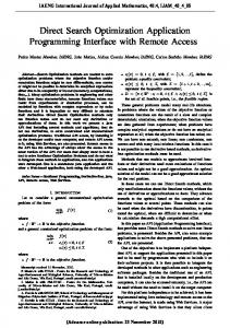
HE following results for a parallel NoC link with W = 16 wires were obtained with the help of Matlab using our spatial faulty wire probability distribution model from (13) and (14). Again, the results were verified to be correct when compared against the results of extensive brute-force simulations in Matlab. Table 1 shows the number of wire arrangements for all possible combinations of F and S , while Fig. 2 shows the distribution of the corresponding probabilities PW ( S | F ).
(13)
i
− ∑N j( j
n0 n1 n , ,..., k −1 )) + fj fj fj
W
U A( f m
m
,
F , S) , fm
where i denotes the index for each of the necklaces corresponding to the H -partitions of F , j the index of the prime common factors of all elements in string r (corresponding to a periodic necklace), and m the index of the prime common factors of W and F . Finally, combining (1), (2), and (13), one can obtain the following formula for the probability distribution
Fig. 2. Probability distribution PW(S|F) for a parallel NoC link with a total of W = 16 parallel wires including F faulty wires, where S is the size of the largest fault-segment.
PW ( S | F ). ⎛W − S − 2 ⎞ ⎟⎟ PW ( S | F ) = W ⎜⎜ ⎝ F −S ⎠
⎛W ⎞ (if ⎡ F + 1⎤ ), ⎜⎜ ⎟⎟ ⎢⎢ 2 ⎥⎥ ≤ S ≤ F ⎝F ⎠ (14)
⎛W ⎞ PW ( S | F ) = A(W , F , S ) ⎜⎜ ⎟⎟ ⎝F⎠
F + 1⎤ ) (if 0 < S < ⎡ ⎢⎢ 2 ⎥⎥
The formula above has been numerically tested and is ISBN: 978-988-19251-3-8 ISSN: 2078-0958 (Print); ISSN: 2078-0966 (Online)
V. AN ARITHMETIC EXAMPLE AND DEMONSTRATION OF THE EFFECTIVENESS OF THE DERIVED MODEL
W
E demonstrate the applicability and, consequently, the effectiveness of the derived model using the following parameters that were chosen at random (relatively large numbers have been picked to show both the efficiency and accuracy of the derived model). Let W = 18 , F = 12 and S = 3. Hence H = 6. The 6partitions of F = 12 , with the largest term being equal to WCE 2012
Proceedings of the World Congress on Engineering 2012 Vol I WCE 2012, July 4 - 6, 2012, London, U.K.
S = 3 are given as follows with the corresponding string r (refer to Section III.F.1): p = 3 + 3 + 3 + 3 + 0 + 0 ~ (4, 0, 0, 2) = r, p = 3 + 3 + 3 + 2 + 1 + 0 ~ (3, 1, 1, 1) = r, p = 3 + 3 + 3 + 1 + 1 + 1 ~ (3, 0, 3, 0) = r, p = 3 + 3 + 2 + 2 + 2 + 0 ~ (2, 3, 0, 1) = r, p = 3 + 3 + 2 + 2 + 1 + 1 ~ (2, 2, 2, 0) = r, p = 3 + 2 + 2 + 2 + 2 + 1 ~ (1, 4, 1, 0) = r. Then, the number of necklaces for each of the partitions above is (refer to (11)): N ( 4,2) = 3 , N (3,1,1,1) = 20 , N (3,3) = 4 , N ( 2,3,1) = 10 , N ( 2,2,2) = 16 , N (1,4,1) = 5 , giving a total of 58 necklaces. Moreover, the number of periodic necklaces is (refer to (12)) K ( 4,2) = N ( 2,1) = 1 , K (3,3) = N (1,1) = 1 , K ( 2,2,2) = N (1,1,1) = 2 , giving a total of 4 periodic necklaces. Using the conjecture established in Section III.G, we find, recursively, the number of periodic wire arrangements W F U A( f , f , S ) = A(18 / 2,12 / 2,3) ∪ A(18 / 3,12 / 3,3) = 33, m m m as A(9,6,3) and A(6,4,2) are disjoint with cardinalities 27 and 6, respectively. The next step is to proceed with the calculation of the total number of wire arrangements using (13) as follows.
A(18,12,3) = W ( ∑ N i − ∑ K j ) + i
j
18 12 , ,3) fm m
U A( f m
= 18(58 4) + 33 = 1005, which is in complete agreement with the brute-force computation. Finally, we compute the desired probability (from (14)) to be
⎛18 ⎞ 1005 . P18 (3 | 12) = A(18,12,3) ⎜⎜ ⎟⎟ = ⎝12 ⎠ 18564
T
results. Next, future, steps, include the rigorous proof of the recursive conjecture established in the presented algorithm, while the derivation of a fully non-recursive algorithm persists as a challenge. REFERENCES [1]
[2]
[3] [4] [5]
[6]
[7] [8] [9] [10] [11] [12] [13] [14]
S.R. Vangal, J. Howard, G. Ruhl, S. Dighe, H. Wilson, J. Tschanz, D. Finan, A. Singh, T. Jacob, S. Jain, V. Erraguntla, C. Roberts, Y. Hoskote, N. Borkar, S. Borkar, “An 80-Tile Sub-100-W TeraFLOPS Processor in 65-nm CMOS,” IEEE Journal of Solid-State Circuits, Vol. 43, No. 1, pp. 29–41, Jan. 2008. S. Bell, B. Edwards, J. Amann, R. Conlin, K. Joyce, V. Leung, J. MacKay, M. Reif, Liewei Bao, J. Brown, M. Mattina, Chyi-Chang Miao, C. Ramey, D. Wentzlaff, W. Anderson, E. Berger, N. Fairbanks, D. Khan, F. Montenegro, J. Stickney, J. Zook, “TILE64 Processor: A 64-Core SoC with Mesh Interconnect,” Proc. of the IEEE Int'l Solid-State Circuits Conference, pp. 588–598, Feb. 2008. W.J. Dally and B. Towles, “Route Packets not Wires: On-Chip Interconnection Networks,” Proc. of the IEEE Design Automation Conference, pp. 684–689, May 2001. J.R. Black, “Electromigration Failure Modes in Aluminum Metallization for Semiconductor Devices,” Proc. of the IEEE, Vol. 57, No. 8, pp. 1587–1594, Sept. 1969. A. Vitkovskiy, V. Soteriou and C. Nicopoulos, “A Fine-Grained LinkLevel Fault-Tolerant Mechanism for Networks-on-Chip,” Proc. IEEE International Conference on Computer Design, pp. 447–454, Oct. 2010. A. Vitkovskiy, V. Soteriou and C. Nicopoulos, “A Dynamically Adjusting Gracefully Degrading Link-Level Fault-Tolerant Mechanism for NoCs,” To appear in the IEEE Transactions on Computer-Aided Design of Integrated Circuits and Systems, 2012. R.C. Lyndon, “On Burnside’s Problem,” Transactions of the American Mathematical Society, Vol. 77, pp. 202–215, 1954. L. Pebody, “Reconstructing Odd Necklaces,” in Combinatorics, Probability and Computing, Vol. 16, pp. 503–514, Feb. 2007. N. Alon, “Splitting Necklaces,” Advances in Mathematics, Vol. 63, No. 3, pp. 247–253, March 1987. S.W. Golomb, “Combinatorial Proof of Fermat’s ‘Little Theorem,” in The American Mathematical Monthly, Vol. 63, No 10, pp. 718, 1956 E.W. Weisstein, “Necklace,” MathWorld--A Wolfram Web Resource, available [online]: http://mathworld.wolfram.com/Necklace.html D.E. Knuth, “The Art of Computer Programming: Vol. 4A Combinatorial Algorithms, Part 1,” Upper Saddle River, New Jersey: Addison-Wesley, 2011, pp xvi+883. The Object Server, “Necklaces, Unlabelled Necklaces, Lyndon Words, De Bruijn Sequences,” Available [online]: http://www.theory.cs.uvic.ca/~cos/inf/neck/NecklaceInfo.html E.W. Weisstein, “Totient Function,” MathWorld--A Wolfram Web Resource, available [online]: http://mathworld.wolfram.com/TotientFunction.html.
VI. CONCLUSION
HIS article derives and demonstrates the combinatoricsbased model which can be used to calculate the spatial probability distribution of wire faults in a parallel NoC interconnect link given its width and a given number of faulty wires which can appear in this link. Particular emphasis was paid upon the adjacency of the faulty wires that form fault-segments separated by at least one healthy wire, as the size of the largest segment determines the additional delay required by data recovery mechanisms, such as the Partially Faulty Link Recovery Mechanism (PFLRM) [9, 10], to recover corrupted flit data at the receiver router. The developed model constitutes a combinatorial application of partitions and necklaces through a systematic approach that derives the correspondence between the presented problem and necklaces, where periodicity plays a crucial role. The model proves to be highly accurate when compared against extensive brute-force numerical simulations and associated ISBN: 978-988-19251-3-8 ISSN: 2078-0958 (Print); ISSN: 2078-0966 (Online)
WCE 2012