A Compact Topological DBMS Data Structure For 3D Topography Friso Penninga and Peter van Oosterom Delft University of Technology, OTB, section GIS Technology, Jaffalaan 9, 2628 BX the Netherlands
[email protected],
[email protected] Summary. The objective is to develop a data structure that is capable of handling large data volumes and offers support for querying, analysis and validation. Based on earlier results (i.e. the full decomposition of space, the use of a TEN structure and applying Poincar´e simplicial homology as mathematical foundation) a simplicial complex-based TEN structure is developed. Applying simplicial homology offers full control over orientation of simplexes and enables one to derive substantial parts of the TEN structure, instead of explicitly store the entire network. The described data structure is developed as a DBMS data structure and the usage of views, function based indexes and 3D R-trees result in a compact topological 3D data structure. Theoretical aspects of this approach are described earlier [12, 17, 18]. This paper describes both theory and implementation of the approach.
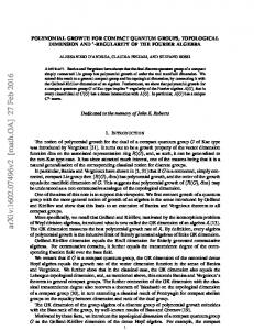
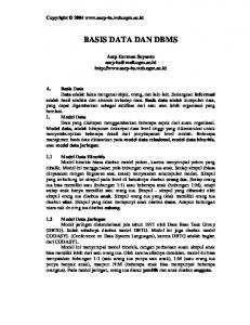
1 Introduction 1.1 Motivation Most current topographic data sets are limited to representing the real world in two dimensions. Nevertheless, due to developments in multiple land use, environmental modelling and data acquisition techniques, attention is shifting towards 3D topographic data modelling. Early 3D developments focused mostly on 3D visualisation, while with the maturing of 3D GIS research the scope has broadened and now also includes 3D query and analysis. As a result the need arised for a data structure capable of storing 3D data and supporting 3D query and analysis (see Figure 1). As data volume increases substantially with the step from 2D to 3D, which is partly due to new high point density data acquisition techniques (see Figure 2), maintaining data consistency becomes an important objective of the new data structure. The objective of the research is to develop a data structure that is capable of handling large data volumes and offers support for querying, analysis and validation. An obvious step in dealing with large data volumes is to use spatial databases. Even though 3D coordinates can be used in some spatial databases,
2
Friso Penninga and Peter van Oosterom
3D data types are still missing [1]. Defining a new 3D data type is part of the research and in this research tetrahedrons will be used as building blocks for the 3D models.
Fig. 1. Increasing reality: analysis in 3D (example from http://www.esri.com)
Fig. 2. Terrestrial laser scanning provides insight in complex objects
1.2 Related research Research in the field of 3D GIS has been performed for about the last two decades. Zlatanova et al. [2] give an overview of the most relevant develop-
2 Previous research
3
ments in this period. Related to the topics introduced in this paper, Carlson [3] can be seen as the starting point as he introduced a simplicial complex-based approach of 3D subsurface structures. However, this approach was limited to the use of 0-, 1- and 2-simplexes in 3D space. Extending this into higher dimensions (as indicated by Frank and Kuhn [4]) is mentioned as a possibility. The explicit use of 3D manifolds to model 3D features is explored by Pigot [5, 6] and Pilouk [7] introduces the TEtrahedral irregular Network (TEN), in which the 3-simplex is used as building block. A topological data model based on 2D simplicial complexes (in 2D space) is introduced [8] and implemented in the PANDA system [9], an early object-oriented database. In applications polyhedrons are often used as 3D primitive [10, 11].
2 Previous research 2.1 Modelling 3D Topography: full decomposition of 3D space With respect to modelling 3D topographic data two fundamental observations are of great importance [12]: • Physical objects have by definition a volume. In reality, there are no point, line or polygon objects, only point, line or polygon representations exist (at a certain level of generalisation). The ISO 19101 Geographic information - Reference model [13] defines features as ’abstractions of real world phenomena’. In most current modelling approaches the abstraction (read ’simplification’) is in the choice for a representation of lower dimension. However, as the proposed method uses a tetrahedral network (or mesh), the simplification is already in the subdivision into easy-to-handle parts (i.e. it is a finite element method!). • The real world can be considered a volume partition: a set of nonoverlapping volumes that form a closed modelled space. As a consequence, objects like ’earth’ or ’air’ are explicitly part of the real world and thus have to be modelled. Inclusion of air and earth objects is often considered unnecessary, thus more serving the abstract goal of ’clean modelling’ than an actual useful goal. This is however not the case. These air and earth objects do not just fill up the space between features of the other types, but are often also subject of analyses, such as noise and odour modelling. Although the model consists of volume features, some planar features might still be very useful, as they mark the boundary (or transition) between two volume features. The new approach supports these planar features, but only as ’derived features’, meaning that these features are lifetime dependent from their parents (the two neighbouring volume features). For instance, a ’wall’ might be the result of the association between a ’house’ and the ’air’. These planar features may even have attributes, but semantically they do not
4
Friso Penninga and Peter van Oosterom
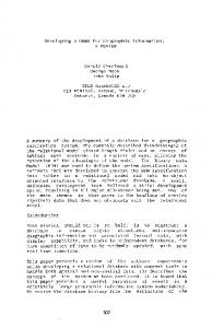
bound the building. In other words: the house is represented by a volume, with neighbouring volumes that may represent air, earth or perhaps another adjacent house. 2.2 Using a Tetrahedral irregular network (TEN) After initial ideas [14] on a hybrid data model (an integrated TIN/TEN model, based on the pragmatic point of view: model in 2,5D where possible and only in exceptional cases switch to a full 3D model) the decision was made [12] to model all features in a single TEN. The preference for these simplex-based data structures is based on certain qualities of simplexes: • Well defined: a n-simplex is bounded by n + 1 (n − 1)-simplexes. E.g. a 2-simplex (triangle) is bounded by 3 1-simplexes (edges) • Flatness of faces: every face can be described by three points • A n-simplex is convex (simplifies amongst others point-in-polygon tests) A disadvantage of simplexes is the introduction of a 1:n relationship between features and their representations. Increasing perceived complexity and data volume are usually the result. However, the problem of complexity might be tackled by a well-designed user interface. An average user should handle features (as polyhedrons) and internally these polyhedrons can be tetrahedronised and inserted into the topographic data model. The data volume problem is tackled in our approach by utilising the mathematical foundations of simplicial complexes. 2.3 Mathematical foundation: Poincar´ e simplicial homology The new volumetric approach uses tetrahedrons to model the real world. These tetrahedrons in the TEN structure consist of nodes, edges and triangles. All four data types are simplexes: the simplest geometry in each dimension. A more formal definition [15] of a n-simplex Sn can be given: a n-simplex Sn is the smallest convex set in Euclidian space IRm containing n + 1 points v0 , . . . , vn that do not lie in a hyperplane of dimension less than n. As the n-dimensional simplex is defined by n + 1 nodes, it has the following notation: Sn =< v0 , . . . , vn >. The boundary of a n-simplex is defined by the following sum of n−1 dimensional simplexes [16] (the hat indicates omitting the specific node): n X ∂Sn = (−1)i < v0 , . . . , vˆi , . . . , vn > i=0
This results in (see Figure 3): S1 =< v0 , v1 > ∂S1 =< v1 > − < v0 > S2 =< v0 , v1 , v2 > ∂S2 =< v1 , v2 > − < v0 , v2 > + < v0 , v1 > S3 =< v0 , v1 , v2 , v3 > ∂S3 =< v1 , v2 , v3 > − < v0 , v2 , v3 > + < v0 , v1 , v3 > − < v0 , v1 , v2 >
2 Previous research
5
Fig. 3. Simplexes and their boundaries (From [15])
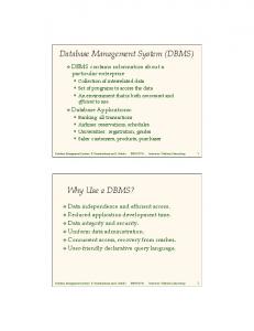
It is assumed that all simplexes are ordered. As a simplex Sn is defined by n+1 vertices, (n+1)! permutations exist. All even permutations of an ordered simplex Sn =< v0 , . . . , vn > have the same orientation, all odd permutations have opposite orientation. So edge S1 =< v0 , v1 > has boundary ∂S1 =< v1 > − < v0 >. The other permutation S1 = − < v0 , v1 >=< v1 , v0 > has boundary ∂S1 =< v0 > − < v1 >, which is the opposite direction. In a similar way the boundaries of the other five combinations of S2 and the other 23 combinations of S3 can be given. As a consequence operators like the dual of a simplex become very simple: it only requires a single permutation. Another favourable characteristic is that with S3 either all normal vectors of the boundary triangles point inwards or all normal vectors point outwards. This is a direct result from the definition of the boundary operator, as it is defined in such a way that ∂ 2 Sn is the zero homomorphism, i.e. the boundary of the boundary equals zero. For example, consider ∂ 2 S3 , a tetrahedron. The boundary of this tetrahedron consist of four triangles, and the boundaries of these triangles consist of edges. Each of the six edges of S3 appears two times, as each edge bounds two triangles. As the zero homomorphism states that the sum of these edges equals zero, this is the case if and only if the edges in these six pairs have opposite signs. The edges of two neighbouring triangles have opposite signs if and only if the triangles have the same orientation, i.e. either both are oriented outwards or both are oriented inwards. This characteristic is important in deriving the boundary of a simplicial complex (construction of multiple simplexes). If this identical orientation is assured for all boundary triangles of tetrahedrons (which can be achieved by a single permutation when necessary), deriving the boundary triangulation of a feature will reduce to adding up boundary triangles of all related tetrahedrons, as internal triangles will cancel out in pairs due to opposite orientation. Figure 4 shows an example in which all boundaries of the tetrahedrons are added up in order to obtain the boundary triangulation of the building.
6
Friso Penninga and Peter van Oosterom
Fig. 4. Deriving the boundary triangulation from the TEN
3 A simplicial complex-based TEN structure 3.1 Conceptual model In a TEN structure tetrahedrons are usually defined by four triangles, triangles by three edges and edges by two nodes. Geometry is stored at node level. As a result reconstructing geometry of for instance a tetrahedron becomes a relatively laborious operation. In simplicial homology simplexes of all dimensions are defined by their vertices. Relationships between other simplexes, for instance between tetrahedrons and triangles, can be derived by applying the boundary operator. As a result [17], there is no need for explicit storage of these relationships. This concept is illustrated in the UML class diagram in Figure 5. The associations between the tetrahedron, triangle and edge class and the node class show that these simplexes are specified by an ordered list of nodes. The interrelationships between tetrahedrons, triangles and nodes (the boundary/coboundary relationships) are derived and signed (i.e. oriented). Figure 5 shows also the concept of the full decomposition of space. The real world consists of volume features and features of lower dimension are modelled as association classes. As a result, instances of these classes are lifetime dependent from a relationship between two volume features.
3 A simplicial complex-based TEN structure
Fig. 5. UML class diagram of the simplicial complex-based approach
7
8
Friso Penninga and Peter van Oosterom
3.2 Vertex encoding In the simplicial complex-based approach simplexes will be defined by their vertices, resulting in a lot of references to these vertices. Since the geometry is the only attribute of a vertex, adding a unique identifier to each point and building an index on top of this table will cause a substantial increase in data storage. To deal with this an alternative approach is used. It is based on the observation that adding a unique identifier is a bit redundant, as the geometry in itself will be a unique identifier as well. To achieve this the coordinate pair is concatenated into one long identifier code. Sorting this list will result in a very basic spatial index. In a way this approach can be seen as building and storing an index, while the original table is deleted. The possibilities of applying techniques like bitwise interleaving, 3D Morton or Peano-Hilbert coding are recognised, but for reasons of insightfulness the concatenated version will be used in this paper. Figure 6 illustrates this idea of vertex encoding in a simplicial complexbased approach. A house is tetrahedronised and the resulting tetrahedrons are coded as concatenation of their four vertices’ coordinates. Each row in the tetrahedron encoding can be interpreted as x1 y1 z1 x2 y2 z2 x3 y3 z3 x4 y4 z4 . For reasons of simplicity only two positions are used for each coordinate element. Therefore the last row (100000000600100600100608) should be interpret as the tetrahedron defined by the vertices (10, 00, 00), (00, 06, 00), (10, 06, 00) and (10, 06, 08), which is the tetrahedron at the bottom right of the house.
Fig. 6. Describing tetrahedrons by their encoded vertices
4 Implementation: proof of concept In order to provide more insight in the proposed new approach this section will outline the current DBMS implementation. It is developed and tested with a
4 Implementation: proof of concept
9
small test dataset, consisting of 56 tetrahedrons, 120 triangles, 83 edges and 20 nodes. At this moment the required tetrahedronisation algorithms are not implemented yet, although previous research did focus on this topic [17, 18]. As a temporal workaround the test dataset was tetrahedronised by hand and the same dataset was used in a previous implementation (a classical TEN approach). Based on this implementation a 2D viewer (Oracle MapViewer) was adapted for 3D data by the use of a function rotateGeom. Both the implementation and the viewer are described in [17]. In Figure 7 the small dataset can be seen in the MapViewer. The dataset basically represents a small piece of the earth surface with a house and a road on top of it. This section will start with creating the data structure, i.e. to define the table and views to store tetrahedrons, triangles, edges and nodes. After that it will be shown that also the constraints can be derived, so no additional explicit storage is required. The next topic is deriving topological relationships. The section continues with some remarks on validation, followed by some examples on querying and analysis and ends with initial remarks on performance.
Fig. 7. Adapting the 2D MapViewer for 3D data by a function rotateGeom
4.1 Building the data structure The tetrahedron table is the only table in the implementation. It consists of a single column (NVARCHAR2)in which the encoded tetrahedrons are described
10
Friso Penninga and Peter van Oosterom
in the form x1 y1 z1 x2 y2 z2 x3 y3 z3 x4 y4 z4 id. Note that besides the geometry also an unique identifier is added, which refers to a volume feature that is (partly) represented by the tetrahedron. Each tetrahedron has positive orientation, meaning that all normal vectors on boundary triangles are oriented outwards. This consistent orientation is required to ensure that each boundary triangle appears two times: once with positive and once with negative orientation. The orientation simplifies determination of left/right and inside/outside relations. To achieve this, each tetrahedron’s orientation is checked. All tetrahedrons with inward orientation are replaced by tetrahedrons with outward orientation: create or replace procedure tettableoutwards (...) checkorientation(codelength,currenttetcode,bool); if (bool = 0) then permutation12(codelength,currenttetcode,newtetcode); update tetrahedron set tetcode=newtetcode where current of tetcur; (...) The checkorientation procedure compares the direction of the normal vector of one of the boundary triangles with a vector from this triangle to the fourth (opposite) point of the tetrahedron. In case of an inward orientation a single permutation is carried out by the procedure permutation12, which permutes the first and second vertex: permutation12(< v0 , v1 , v2 , v3 >) results in < v1 , v0 , v2 , v3 >. Based on the encoded tetrahedrons the boundary triangles can be derived by applying the boundary operator: create or replace procedure deriveboundarytriangles( (...) a := (SUBSTR(tetcode,1,3*codelength)); b := (SUBSTR(tetcode,1+3*codelength,3*codelength)); c := (SUBSTR(tetcode,1+6*codelength,3*codelength)); d := (SUBSTR(tetcode,1+9*codelength,3*codelength)); id := (SUBSTR(tetcode,1+12*codelength)); ordertriangle(codelength,’+’||b||c||d||id, tricode1); ordertriangle(codelength,’-’||a||c||d||id, tricode2); ordertriangle(codelength,’+’||a||b||d||id, tricode3); ordertriangle(codelength,’-’||a||b||c||id, tricode4); (...) Note that the triangles inherit the object id from the tetrahedron, i.e. each triangle has a reference to the volume feature represented by the tetrahedron of which the triangle is part of the boundary. The reason for this will be introduced in the next section. It can also be seen that each boundary triangle is ordered by the ordertriangle procedure. The objective of this procedure is
4 Implementation: proof of concept
11
to gain control over which permutation is used. A triangle has six (= 3!) permutations, but it is important that both in positive and negative orientation the same permutation is used, as they will not cancel out in pairs otherwise. The ordertriangle procedure always rewrites a triangle < a, b, c > such that a < b < c holds, which is an arbitrary criterion. Slightly altered versions of the deriveboundarytriangles procedure are used to create the triangle view. The modified procedures derive respectively the first, second, third and fourth boundary triangle of a tetrahedron. The resulting view contains all triangles and their coboundaries (the coboundary of a n-dimensional simplex Sn is the set of all (n+1)-dimensional simplexes Sn+1 of which the simplex Sn is part of their boundaries ∂Sn+1 ). In this case the coboundary is the tetrahedron of which the triangle is part of the boundary. This coboundary will prove useful in deriving topological relationships later in this section. The view is created as: create or replace view triangle as select deriveboundarytriangle1(3,tetcode) tetcode fromtetcode from tetrahedron UNION ALL select deriveboundarytriangle2(3,tetcode) tetcode fromtetcode from tetrahedron UNION ALL select deriveboundarytriangle3(3,tetcode) tetcode fromtetcode from tetrahedron UNION ALL select deriveboundarytriangle4(3,tetcode) tetcode fromtetcode from tetrahedron;
tricode,
tricode,
tricode,
tricode,
The resulting view will contain four times the number of tetrahedrons, and every triangle appears two times: once with positive and once with sign negative sign (and not in a permutated form, due to the ordertriangle procedure). In a similar way the views with edges and nodes can be constructed. In current implementation edges are undirected en do not inherit object ids, as no application for this is identified at the moment. However, strict application of the boundary operator would result in directed triangles. With the tetrahedron table and triangle, edge and node view the data structure is accessible at different levels. Due to the encoding of the vertices, both geometry and topology are present at every level, thus enabling switching to the most appropriate approach for every operation. 4.2 Creating views with derived constraints Features in the model are represented by a set of tetrahedrons. To ensure that these tetrahedrons represent the correct geometry, the outer boundary is triangulated and these triangles are used as constraints. This implies that these triangles will remain present as long as the feature is part of the model
12
Friso Penninga and Peter van Oosterom
(i.e. they are not deleted in a flipping proces). To achieve this, the incremental tetrahedronisation algorithm needs to keep track of these constrained triangles. In contrast with what one might expect, it is not necessary to store these constraints explicitly, as they can be derived as well: create or replace view constrainedtriangle as select t1.tricode tricode from triangle t1 where not exists (select t2.tricode from triangle t2 where t1.tricode = t2.tricode*-1); This statement uses the fact that although every triangle (in a geometric sense) appears two times (with opposite orientation) in the triangle view, not every triangle code appears two times. As stated before the triangle code inherits the object id from the tetrahedron (its coboundary). This implies that for internal triangles (i.e. within an object) the triangle and its dual will have (apart from the sign) the exact same triangle code (geometry + object id), but in case of boundary triangles (i.e. constrained triangles) this code will differ due to the different inherited object id’s. So in simplified form, consider triangle codes -1,7,2,-7,-3 and 1. In this case triangles 2 and -3 will be constrained triangles. The inherited object id’s can also be used in visualisations in order to derive the colour or texture. Deriving constrained edges from constrained triangles is straightforward, as all boundary edges from constrained triangles are constrained edges. 4.3 Creating views with derived topological relationships In a TEN the number of possible topological relationships is limited. As the TEN can be considered as a decomposition of space, relationships like overlap, cover or inside do not occur. Only relationships based on the interaction between tetrahedron boundaries occur. Tetrahedrons (and their boundaries) are either disjoint or touch. The case in which two boundary triangles touch (i.e. the faces touch each other) is the neighbour relation. Two related relationships are derived in views in the implementation. The first is the relationship between a triangle and its dual. This relationship is important in the proces of finding neighbours from tetrahedrons. The view is created by a select statement that uses the identical geometric part of the triangle codes: create or replace view dualtriangle as select t1.tricode tricode, t2.tricode dualtricode from triangle t1, triangle t2 where removeobjectid(3,t2.tricode) = -1 *removeobjectid(3,t1.tricode); By combining the triangle view and the dualtriangle view, neighbouring tetrahedrons can be found:
4 Implementation: proof of concept
13
create or replace function getneighbourtet1( (...) select fromtetcode into neighbourtet from triangle where tricode = (select dt.dualtricode from dualtriangle dt where dt.tricode = deriveboundarytriangle1(codelength,tetcode)); (...) and based on functions like this one the view with tetrahedrons and their neighbours can be created. 4.4 Validating the data structure A TEN is valid when it is a full decomposition of space, i.e. there are no overlaps or gaps in the structure. Additional requirements are that each tetrahedron has positive orientation, meaning that the normal vectors of the bounding triangles all point outwards. The data structure can be validated by applying the Euler-Poincar´e formula: N −E +F −V = 0 with N the number of nodes, E the number of edges, F the number of faces and V the number of volumes (including the exterior). As can be seen in Figure 8, the Euler-Poincar´e formula holds for all simplicial complexes, including simplicial complexes that consist of simplexes of different dimensions. Due to this characteristic dangling edges and faces cannot be detected, but for instance holes (i.e. missing faces) can be detected. Within the simplicial complex-based approach the validation strategy is to start with a valid tetrahedronisation and to check every update for correctness before committing it to the database. As a result one will migrate from one valid state into another valid state. This strategy will also include the application of for instance flipping algorithms for the deletion of vertices [19], as such algorithms are designed to maintain a valid TEN during each step of the proces. Other correctness checks can be implemented, like for instance a check on the triangle view to ensure that every triangle appears two times (with opposite sign, ignoring the inherited object id’s). Also validation on feature level can be considered, for instance one can check whether all constrained triangles form a valid polyhedron. For more details on the validation of polyhedrons, see [20]. 4.5 Query and analysis The presence of views helps to simplify a lot of queries as the functions on which the views are based can be omitted from the queries. The most frequently used elements and relationships are made available through these views. If one is interested in for instance a boundary representation of a feature, one could query the constrained triangle view with a specific object id.
14
Friso Penninga and Peter van Oosterom
Fig. 8. Using Euler-Poincar´e in 2D and 3D for validation: dangling edges and faces remain undetected
The resulting set of constrained triangles will form a valid polyhedron, see Figure 9 for an example. One might consider to simplify this polyhedron further by merging triangles with identical (given a specific tolerance) normal vectors into polygons. However, a polyhedron may consist of triangular faces and these triangulation might be useful for visualisation purposes. The number of analyses that can be performed on the TEN structure is virtually unlimited. One can think of basic operations like distance, line-of-sight or volume calculations, or more complex operations like tetrahedron-based buffer and overlay [21]. Also a wide variety of simulations can be performed on the tetrahedral mesh, like flooding or air flow simulations. Tetrahedronal meshes can be used and optimized for simulation purposes [22, 23]. 4.6 Performance The tetrahedron table is potentially very large, so indexing becomes an important aspect of the data structure. Sorting the table on the tetrahedron code will function as an index, as tetrahedrons in a particular area will be stored closed to each other in the table as well. However, a secondary index might still be needed. As the tetrahedron code contains all geometry, constructing the minimal bounding boxes and building a R-tree will be a logical step. To ensure performance for queries on the views, function based indexes are created for all functions that are used to create views.
5 Discussion and Conclusions
15
Fig. 9. Output in VRML: result of select tricode from constrainedtriangle where getobjectid(3,tricode)=3;. This is the same object as in Figure 7
5 Discussion and Conclusions 5.1 Discussion An important question is whether the proposed method is innovative. As mentioned in section 1.2 both the idea to use a TEN data structure for 3D data and using simplexes (in terms of simplicial homology) in a DBMS implementation are described by other. However, the proposed approach reduces data storage and eliminates the need for explicit updates of both topology and less dimensional simplexes. By doing so, the approach tackles common drawbacks as TEN extensiveness and laboriousness of maintaining topology. Furthermore, applying simplicial homology offers full control over orientation of simplexes, which is a huge advantage especially in 3D. Integrating these concepts with database functionality results in a new innovative approach to 3D data modelling. 5.2 Conclusions As stated in the introduction, the objective of this research is to develop a data structure that is capable of handling large data volumes and offers support for querying, analysis and validation. Based on earlier results (i.e. the full decomposition of space, the use of a TEN structure and applying Poincar´e simplicial homology as mathematical foundation) a simplicial complex-based
16
Friso Penninga and Peter van Oosterom
TEN structure is developed. Applying simplicial homology offers full control over orientation of simplexes and enables one to derive substantial parts of the TEN structure, instead of explicitly store the entire network. As a result only the single column tetrahedron table has to be stored explicitly. Due to the encoded vertices and inheritance of object id’s all constrained edges and faces can be derived, thus avoiding redundant data storage. Since the topological relationships are also derived, updating the structure turns out to be limited to updating the tetrahedron tables. All implicit updates in less dimensional simplexes or topological relationships propagate from this single update action. The described data structure is developed as a DBMS data structure. Spatial DBMS characteristics as the usage of views, function based indexes and 3D R-trees are extensively used and contribute to the compactness and versatility of the data structure. Furthermore a database is capable of coping with large data volumes, which is an essential characteristic in handling large scale 3D data.
References 1. Kothuri, R., Godfrind, A., Beinat, E.: Pro Oracle Spatial: The essential guide to developing spatially enabled business applications. Apress (2004) 2. Zlatanova, S., Abdul Rahman, A., Pilouk, M.: 3D GIS: Current Status and Perspectives. In: Proceedings of Joint Conference on Geo-Spatial Theory, Processing and Applications, Ottawa, Canada. (2002) 3. Carlson, E.: Three-dimensional conceptual modeling of subsurface structures. In: Auto-Carto 8. (1987) 336–345 4. Frank, A.U., Kuhn, W.: Cell Graphs: A provable Correct Method for the Storage of Geometry. In: Proceedings of the 2nd International Symposium on Spatial Data Handling, Seattle, Washington. (1986) 5. Pigot, S.: A Topological Model for a 3D Spatial Information System. In: Proceedings of the 5th International Symposium on Spatial Data Handling. (1992) 344–360 6. Pigot, S.: A topological model for a 3-dimensional Spatial Information System. PhD thesis, University of Tasmania, Australia (1995) 7. Pilouk, M.: Integrated Modelling for 3D GIS. PhD thesis, ITC Enschede, Netherlands (1996) 8. Egenhofer, M., Frank, A., Jackson, J.: A Topological Data Model for Spatial Databases. In: Proceedings of First Symposium SSD’89. (1989) 271–286 9. Egenhofer, M., Frank, A.: PANDA: An Extensible Dbms Supporting ObjectOriented Software Techniques. In: Datenbanksysteme in B¨ uro, Technik und Wissenschaft. Proceedings of GI/SI Fachtagung, Z¨ urich, 1989. Informatik Fachberichten, Springer-Verlag (1989) 74–79 10. Zlatanova, S.: 3D GIS for urban development. PhD thesis, Graz University of Technology (2000) 11. Stoter, J.: 3D Cadastre. PhD thesis, Delft University of Technology (2004) 12. Penninga, F.: 3D Topographic Data Modelling: Why Rigidity Is Preferable to Pragmatism. In Cohn, A.G., Mark, D.M., eds.: Spatial Information Theory,
References
13. 14.
15. 16. 17.
18.
19.
20. 21.
22.
23.
17
Cosit’05. Volume 3693 of Lecture Notes on Computer Science., Springer (2005) 409–425 ISO/TC211: Geographic information - reference model. Technical Report ISO 19101, International Organization for Standardization (2005) Penninga, F.: Towards 3D Topography using a Feature-based Integrated TIN/TEN Model. In Toppen, F., Painho, M., eds.: AGILE 2005, 8th Conference on Geographic Information Science. Conference Proceedings. Estoril, Portugal, May 26-28. (2005) 373–381 Hatcher, A.: Algebraic Topology. Cambridge University Press (2002) Available at http://www.math.cornell.edu/∼hatcher Poincar´e, H.: Compl´ement ´ a l’Analysis Situs. Rendiconti del Circolo Matematico di Palermo 13 (1899) 285–343 Penninga, F., van Oosterom, P., Kazar, B.M.: A TEN-based DBMS approach for 3D Topographic Data Modelling. In Riedl, A., Kainz, W., Elmes, G., eds.: Progress in Spatial Data Handling, 12th International Symposium on spatial Data Handling, Springer (2006) 581–598 Penninga, F., van Oosterom, P.: Updating Features in a TEN-based DBMS approach for 3D Topographic Data Modelling. In Raubal, M., Miller, H.J., Frank, A.U., Goodchild, M.F., eds.: Geographic Information Science, Fourth International Conference, GIScience 2006, M¨ unster, Germany, September 2006, Extended Abstracts. Volume 28 of IfGI prints. (2006) 147–152 Ledoux, H., Gold, C.M., Baciu, G.: Flipping to robustly delete a vertex in a Delaunay tetrahedralization. In: Proceedings International Conference on Computational Science and its Applications-ICCSA 2005. Volume 3480 of Lecture Notes on Computer Science., Springer (2005) 737–747 Arens, C., Stoter, J., van Oosterom, P.: Modelling 3D spatial objects in a geoDBMS using a 3D primitive. Computers & Geosciences 31(2) (2005) 165–177 Verbree, E., van der Most, A., Quak, W., van Oosterom, P.: Towards a 3D Feature Overlay through a Tetrahedral Mesh Data Structure. Cartography and Geographic Information Science 32(4) (2005) 303–314 Joe, B.: Construction of three-dimensional improved-quality triangulations using local transformations. SIAM Journal on Scientific Computing (6) (1995) 1292–1307 Cutler, B., Dorsey, J., McMillan, L.: Simplification and Improvement of Tetrahedral Models for Simulation. In Scopigno, R., Zorin, D., eds.: Proceedings of Eurographics Symposium on Geometry Processing. (2004) 93–102