Florida Institute of Technology,. Melbourne, FL 32901. This paper presents the definition of a coordinate frame, entitled the principal frame PF , that is useful for ...
A Coordinate Frame Useful for RigidBody Displacement Metrics Venkatesh Venkataramanujam Pierre M. Larochelle Department of Mechanical and Aerospace Engineering, Robotics and Spatial Systems Laboratory, Florida Institute of Technology, Melbourne, FL 32901
This paper presents the definition of a coordinate frame, entitled the principal frame 共 PF兲, that is useful for metric calculations on spatial and planar rigid-body displacements. Given a set of displacements and using a point mass model for the moving rigidbody, the PF is determined from the associated centroid and principal axes. It is shown that the PF is invariant with respect to the choice of fixed coordinate frame as well as the system of units used. Hence, the PF is useful for left invariant metric computations. Three examples are presented to demonstrate the utility of the PF. 关DOI: 10.1115/1.4002245兴
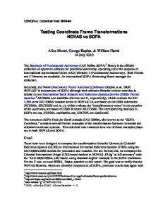
The PF has been introduced to support the ongoing development of polar decomposition based metrics on the displacement groups 关21–23兴. These techniques are based on the polar decomposition 共PD兲 of the homogenous transform representation of the elements of SE共N兲 and the principal frame 共PF兲 associated with the finite set of rigid-body displacements. The mapping of the elements of the special Euclidean group SE共N-1兲 to SO共N兲 yields hyperdimensional rotations that approximate the rigid-body displacements. Conceptual representations of the mapping of SE共N-1兲 to SO共N兲 are shown in Figs. 1 and 2. Once the elements are mapped to SO共N兲 distances can then be evaluated by using a bi-invariant metric on SO共N兲. Due to the use of the PF, the resulting metric on SE共N − 1兲 is left invariant 共i.e., independent of the choice of fixed frame F兲.
2
Metric on SO(N)
Here, we briefly the review the use of the polar decomposition to yield the hyperdimensional rotations that approximate spatial or planar displacements. The elements in SO共N兲 are derived from homogenous transformations representing planar SE共2兲 or spatial SE共3兲 displacements by polar decompositions, as shown in Fig. 2 and derived in Refs. 关21,24兴. The distance between any two elements 关A1兴 and 关A2兴 in SO共N兲 is determined by using the Frobenius norm as follows: d = 储关I兴 − 关A2兴关A1兴T储F
1
共1兲
Introduction
The focus here is on presenting a methodology for identifying a useful fixed frame for performing metric computations on finite sets of planar or spatial displacements. A metric is used to measure the distance between two points in a set. There are various metrics for finding the distance between two points in Euclidean space. However, finding the distance between two locations of a rigid-body is still the subject of ongoing research, see Refs. 关1–13兴. Kazerounian and Rastegar 关13兴 defined metrics that depend on the shape and mass density of the finite moving body. More recently, Sharf et al. 关14兴 discussed Riemannian and Euclidean averages for rigid-body rotations and Angeles 关15兴 investigated the use of characteristic lengths that are used to combine translations and rotations in some manner for use in distance metrics. Furthermore, Zhang and Ting 关16兴 examined Riemannian metrics on point-line displacements. Finally, Di Gregorio 关17兴 sought to employ a geometric approach to identify useful distance metrics. For two locations of a rigid-body 共either SE共2兲-planar or SE共3兲spatial兲 all metrics yield a distance, which is dependent on the chosen fixed or moving frames of reference and the units used, see Refs. 关4,7兴. But, a metric independent of these choices, referred to as bi-invariant, is desirable. Metrics independent of the choice of coordinate frames and the units used do exist on SO共N兲, see the work of Larochelle and McCarthy 关8兴. One bi-invariant metric defined by Ravani and Roth 关18兴 defines the distance between two orientations of a rigid-body as the magnitude of the difference between the associated quaternions. Of related background interest are the works by Horn 关19兴 and Shoemake and Duff 关20兴. Horn solved the problem of finding the rigid-body transformation between two coordinate frames using point coordinates by using Hamilton’s quaternions, whereas Shoemake and Duff examined the problem of decomposing homogeneous rigid-body displacements into rotations and translations using the polar decomposition. Contributed by the Mechanisms and Robotics Committee of ASME for publication in the JOURNAL OF MECHANISMS AND ROBOTICS. Manuscript received July 25, 2008; final manuscript received July 19, 2010; published online September 30, 2010. Assoc. Editor: Frank C. Park.
Journal of Mechanisms and Robotics
It has been verified that this is a valid metric on SO共N兲, see Ref. 关25兴.
3
Finite Sets of Locations
As was reviewed in Sec. 2, the elements of SE共N − 1兲 can be approximated by elements of SO共N兲 by using the polar decomposition. However, the metric on SO共N兲 will not be well defined because of its dependence on the choice of fixed reference frame. In order to yield a useful metric for a finite set of displacements, the principal frame 共PF兲 is introduced. The principal frame is unique for a finite set of displacements and invariant with respect to the choice of fixed coordinate frame and the system of units, see Refs. 关26,27兴. All of the displacements are then expressed with respect to the principal frame and all distances are measured with respect to this same frame. Hence, the polar decomposition based metric yields results that are invariant with respect to the choice of fixed frame. Next, we present the detailed implementation of this methodology. Consider the case when a finite number of n displacements 共n ⱖ 2兲 are given and we have to find the magnitude of these displacements. The displacements depend on the coordinate frames and the system of units chosen. In order to yield a left invariant metric, we utilize a PF that is derived from a unit point mass model for a moving body as suggested by Larochelle 关24兴. A unit point mass is assigned to the origin of each of the coordinate frames representing rigid-body displacements, as shown in Fig. 3. The point masses are then used to determine the center of mass of the system and, eventually, the invariant principal frame of the set of displacements, as shown in Fig. 4. This is done to yield a metric that is independent of the geometry and mass distribution of the moving body. The center of mass and the principal frame are unique for the system and invariant with respect to both the choice of fixed coordinate frame and the system of units 关26,27兴. The procedure for determining the center of mass c and the PF associated with the n prescribed locations is now described. A unit point mass is located at the origin of each location, as shown in Figs. 3 and 4.
Copyright © 2010 by ASME
NOVEMBER 2010, Vol. 2 / 044503-1
RN2 SE(N-1)
[T]
2 M6
M5 1.5
M7 M4
1 M8
[P]
Tangent Plane to SO(N) at [P]
0.5 M9
M3
M10
0
F
M11
−0.5 M2
SO(N)
−1
M1
−2
−1.5
−1
Fig. 1 SE„N − 1… to SO„N…
−0.5
0
0.5
1
1.5
2
Fig. 3 Unit point mass model
n
兺
1 c= di n i=1
共2兲
where di is the translation vector associated with the ith location 共i.e. the origin of the ith location with respect to F兲. The PF is defined such that its axes are aligned with the principal axes of the n point mass system and its origin is at the centroid c. After finding the centroid of the system, we determine the principal axes of the point mass system as follows. The inertia tensor is computed from n
关I兴 = 关1兴
兺
tensor are not unique; i.e., both vi and −vi are eigenvectors associated with 关I兴. In order to resolve this ambiguity and yield a unique PF, we choose the eigenvector directions that most closely aligned PF to F. Note that in the planar case, the PF reduces to a 3 ⫻ 3 matrix 关PF兴 =
i=1
兺dd i=1
冋
册
关− v2 v1 v3 兴
where vi are the principal axes 共eigenvectors兲 associated with the inertia tensor 关I兴, see the work of Greenwood 关26兴. The directions of the vectors along the principal axes vi are chosen such that the principal frame is a right-handed system. However, Eq. 共4兲 does not uniquely define the PF since the eigenvectors vi of the inertia
关v2 v1 − v3 兴
0
0
0 1
2 M5
SE(N-1)
共5兲
关− v1 − v2 v3 兴
共4兲
关PF兴 =
册
关v2 − v1 v3 兴
where 关I兴 is the 3 ⫻ 3 共spatial兲 or 2 ⫻ 2 共planar兲 identity matrix. The principal frame is then determined to be v1 v2 v3 c
0 1
0
关v1 v2 v3 兴
共3兲
T i i
v1 v2 c
The eight different right-handed PF orientations that are possible in the spatial case are
n
储di储2 −
冋
M6
1.5
M7
M4
T1
1
T2
M8
PF
0.5
M9
M3
Polar Decomposition
SO(N) A1
A2
0
M10
F
M11
−0.5 M2
−1
M1
Frobenius Norm −1.5
Fig. 2 Mapping to SO„N…
044503-2 / Vol. 2, NOVEMBER 2010
−1
−0.5
0
0.5
1
1.5
2
Fig. 4 Unit point mass model and associated PF
Transactions of the ASME
Table 1 11 planar locations x
y
共deg兲
Mag.
⫺1.0000 ⫺1.2390 ⫺1.4204 ⫺1.1668 ⫺0.5657 ⫺0.0292 0.2632 0.5679 1.0621 1.6311 2.0000
⫺1.0000 ⫺0.5529 0.3232 1.2858 1.8871 1.9547 1.5598 0.9339 0.3645 0.0632 0.0000
90.0000 77.3621 55.0347 30.1974 10.0210 1.7120 10.0300 30.1974 55.0346 77.3620 90.0000
2.0076 1.7762 1.3165 0.7483 0.2644 0.0807 0.2606 0.7464 1.3159 1.7762 2.0078
v2
v1
F
Fig. 5 Four possible orientations for the PF
关v1 − v2 − v3 兴 关− v2 − v1 − v3 兴 关− v1 v2 − v3 兴 and in the planar case there are four possible orientations of the PF, as seen in Fig. 5,
5
Example: 11 Planar Locations
Consider the rigid-body guidance problem proposed by J. Michael McCarthy, U.C. Irvine for the 2002 ASME International Design Engineering Technical Conferences held in Montreal, Quebec, as shown in Fig. 3 关28兴. The 11 planar locations are listed in Table 1 and the origins of the coordinate frames with respect to the fixed reference frame F are shown in Fig. 4. The centroid and the principal axes directions are calculated and used to determine the PF 共Fig. 6兲
冤
关v1 − v2 兴 关− v2 v1 兴 The PF is selected as the frame that is most closely oriented, per Eq. 共1兲, to the fixed frame. However, there are degenerate cases that must now be addressed. In the degenerate planar case in which the lines defining the PF form equal angles 共i.e., 45 deg兲 with the axes of the fixed frame, then all four possible orientations will be equidistant to the fixed frame’s orientation. In this case, we define the x-axis of the PF along the eigenvector in the first quadrant. In the similarly degenerate spatial case, in which the eigenvectors form equal angles 共i.e., 54.7 deg兲 with each axis of the fixed frame, we define the x-axis of the PF along the eigenvector in the first octant and the y and z axes are chosen such that PF is the frame that is most closely oriented, per Eq. 共1兲, to the fixed frame.
4
Summary of the PF and PD Metric Technique
For a set of n finite rigid-body locations the steps to be followed are as follows: 1. Determine the PF associated with the n locations. 2. Determine the relative displacements from the PF to each of the n locations. 3. Determine the characteristic length R associated with the n displacements with respect to the PF and scale the translation terms in each by 1 / R. 4. Compute the projections of PF and each of the scaled relative displacements using the polar decomposition. 5. The magnitude of the displacement is defined as the distance from the PF to the scaled relative displacement as computed via Eq. 共1兲. The distance between any two of the n locations is similarly computed by the application of Eq. 共1兲 to the projected scaled relative displacements. Journal of Mechanisms and Robotics
0.0067 0.0094
关PF兴 = − 0.0067 1.0000 0.6199 0.0000 0.0000 1.0000
关v1 v2 兴 关v2 − v1 兴
1.0000
冥
共6兲
Note that this PF differs from that originally reported in Ref. 关21兴 due to the more rigorous methodology presented here. The 11 locations are now determined with respect to the PF and the maximum translational component is found to be 1.9947 and the resulting characteristic length is R = 24L / = 15.239. To illustrate the utility of the PF, we present its application for distance metric calculations per Ref. 关21兴. The 11 locations are then scaled by the characteristic length in order to find the distance to the principal frame. The magnitude of each of the displacements with respect to the PF is listed in Table 1. The distance between any two of the locations is computed by the
2 M6
M5
1.5
M7
M4 1 M8 PF 0.5 M9
M3
M10
0
F
M11
−0.5 M2
−1
M1 −1.5
−1
−0.5
0
0.5
1
1.5
2
Fig. 6 Principal frame for eleven desired locations
NOVEMBER 2010, Vol. 2 / 044503-3
Table 2 Ten desired locations
Table 3 Ten desired locations
x
y
z
Long 共兲
Lat 共兲
Roll 共兲
x
y
z
Long 共兲
Lat 共兲
Roll 共兲
1 2 3 4 5 6 7 8 9 10
0 0 0 0 0 0 0 0 0 0
5 4 3 2 1 ⫺1 ⫺2 ⫺3 ⫺4 ⫺5
100 90 80 70 60 50 40 30 20 10
0 0 0 0 0 0 0 0 0 0
0 10 20 30 40 50 60 70 80 90
5.0 4.0 3.0 4.0 5.0 6.0 7.0 8.0 8.5 9.0
9.0 8.0 7.0 6.0 5.5 5.0 6.0 7.0 8.0 9.0
1.0 2.0 3.0 4.5 5.0 6.0 7.0 8.0 8.5 8.0
100 90 80 70 60 50 40 30 20 10
20 30 35 45 57 35 45 50 72 85
35 10 20 30 40 50 60 70 80 90
application of Eq. 共1兲 to the projected scaled relative displacements. For example, the distance between locations 1 and 2 was found to be 0.3115.
6
Example: Ten Spatial Locations
Consider the rigid-body guidance problem investigated by Larochelle 关24兴. The ten spatial locations with respect to the fixed reference frame F are listed in Table 2 and shown in Fig. 7. The principal frame is given by
关PF兴 =
冤
0.756
0.655
0.000 5.500
0.000
0.000
1.000 0.000
0.655 − 0.756 0.000 0.000 0.000
0.000
0.000 1.000
冥
共7兲
Example: Pick and Place Task
Consider the following rigid-body guidance problem representing a spatial pick and place operation commonly found in an industrial assembly line. The ten spatial locations with respect to the fixed reference frame F are listed in Table 3 and shown in Fig. 8. The principal frame is given by
冤
0.378
0.002
0.880
− 0.702 5.950 0.475
7.050
0.797 − 0.289
0.530
5.300
0.000
0.000
1.000
0.000
冥
共8兲
The maximum translational component L is found to be 4.0920 and the associated characteristic length is R = 24L / = 31.2602. The distance from the first location to the principal frame was found to be 2.8135. The distance between locations 1 and 2 was found to be 0.7842.
8
The maximum translational component L is found to be 6.7256 and the associated characteristic length is R = 24L / = 51.3795. The distance from the first location to the principal frame was found to be 2.7488. The distance between locations 1 and 2 was found to be 0.3485.
7
关PF兴 =
0.603
Conclusions
A coordinate frame, entitled the principal frame 共PF兲, that is useful for metric calculations on spatial and planar rigid-body displacements was rigorously defined and presented. Given a set of displacements and using a point mass model for the moving rigid-body, the PF is determined from the associated centroid and principal axes. It was shown that the PF is left invariant, i.e., independent of both the choice of the fixed coordinate frame and the system of units used. Hence, by defining relative displacements with respect to the PF, the PF has proven useful in obtaining left invariant distance metric computations. Three examples that utilized the PF and the polar decomposition based metric of Larochelle et al. 关21兴 were presented to demonstrate the utility of the PF. The principal frame has potential applications in mechanism approximate motion synthesis, robot motion planning, and other applications, which benefit from left invariant metrics on the spatial and planar displacement groups.
T1 T2 T3 T4
PF T5
T6 F
T7 T8 T9 T10
Fig. 7 Principal frame for ten desired locations
044503-4 / Vol. 2, NOVEMBER 2010
Fig. 8 Principal frame for the pick and place task
Transactions of the ASME
Acknowledgment This material is based on the work supported by the National Science Foundation under Grant No. 0422705.
关14兴 关15兴
References 关1兴 Park, F., and Brocket, R., 1994, “Kinematic Dexterity of Robotic Mechanisms,” Int. J. Robot. Res., 13共1兲, pp. 1–15. 关2兴 Lin, Q., and Burdick, J., 2000, “Objective and Frame-Invariant Kinematic Metric Functions for Rigid Bodies,” Int. J. Robot. Res., 19共6兲, pp. 612–625. 关3兴 Bobrow, J., and Park, F., 1995, “On Computing Exact Gradients for Rigid Body Guidance Using Screw Parameters,” Proceedings of the ASME Design Engineering Technical Conferences, New York, NY, ASME, New York, Vol. 1, pp. 839–844. 关4兴 Park, F., 1995, “Distance Metrics on the Rigid-Body Motions With Applications to Mechanism Design,” ASME J. Mech. Des., 117共1兲, pp. 48–54. 关5兴 Chirikjian, G., 1998, “Convolution Metrics for Rigid Body Motion,” Proceedings of the ASME Design Engineering Technical Conferences, New York, NY, ASME, New York, Vol. 1. 关6兴 Chirikjian, G., and Zhou, S., 1998, “Metrics on Motion and Deformation of Solid Models,” ASME J. Mech. Des., 120, pp. 252–261. 关7兴 Martinez, J., and Duffy, J., 1995, “On the Metrics of Rigid Body Displacements for Infinite and Finite Bodies,” ASME J. Mech. Des., 117共1兲, pp. 41– 47. 关8兴 Larochelle, P., and McCarthy, J. M., 1995, “Planar Motion Synthesis Using an Approximate Bi-Invariant Metric,” ASME J. Mech. Des., 117共4兲, pp. 646– 651. 关9兴 Etzel, K. R., and McCarthy, J. M., 1996, “A Metric for Spatial Displacement Using Biquaternions on SO共4兲,” Proceedings of the 1996 IEEE International Conference on Robotics and Automation. 关10兴 Gupta, K. C., 1997, “Measures of Positional Error for a Rigid Body,” ASME J. Mech. Des., 119共3兲, pp. 346–348. 关11兴 Tse, D., and Larochelle, P., 2000, “Approximating Spatial Locations With Spherical Orientations for Spherical Mechanism Design,” ASME J. Mech. Des., 122共4兲, pp. 457–463. 关12兴 Eberharter, J., and Ravani, B., 2004, “Local Metrics for Rigid Body Displacements,” ASME J. Mech. Des., 126, pp. 805–812. 关13兴 Kazerounian, K., and Rastegar, J., 1992, “Object Norms: A Class of Coordinate and Metric Independent Norms for Displacements,” Proceedings of the
Journal of Mechanisms and Robotics
关16兴 关17兴 关18兴 关19兴 关20兴 关21兴 关22兴 关23兴 关24兴 关25兴 关26兴 关27兴 关28兴
ASME 1998 Design Engineering Technical Conferences and Computers and Information Conference. Sharf, I., Wolf, A., and Rubin, M., 2008, “Arithmetic and Geometric Solutions for Average Rigid-Body Rotation,” Mech. Mach. Theory, 45共9兲, pp. 1239– 1251. Angeles, J., 2005, “Is There a Characteristic Length of a Rigid-Body Displacement,” Proceedings of the 2005 International Workshop on Computational Kinematics. Zhang, Y., and Ting, K., 2008, “Point-Line Distance Under Riemannian Metrics,” ASME J. Mech. Des., 130共9兲, p. 092304. Di Gregorio, R., “A Novel Point of View to Define the Distance Between Two Rigid-Body Poses,” Proceedings of the 11th International Symposium on Advances in Robot Kinematics 共ARK兲. Ravani, B., and Roth, B., 1983, “Motion Synthesis Using Kinematic Mappings,” ASME J. Mech., Transm., Autom. Des., 105, pp. 460–467. Horn, B., 1987, “Closed-Form Solution of Absolute Orientation Using Unit Quaternions,” J. Opt. Soc. Am., 4共4兲, pp. 629–642. Shoemake, K., and Duff, T., 1992, “Matrix Animation and Polar Decomposition,” Proceedings of the Conference on Graphics Interface ‘92, Vancouver, BC, Canada, Morgan Kaufmann, San Francisco, CA. Larochelle, P., Murray, A., and Angeles, J., 2007, “A Distance Metric for Finite Sets of Rigid-Body Displacements via the Polar Decomposition,” ASME J. Mech. Des., 129共8兲, pp. 883–886. Venkataramanujam, V., 2007, “Approximate Motion Synthesis of Robotic Mechanical Systems,” MS thesis, Florida Institute of Technology, Melbourne, FL. Venkataramanujam, V., and Larochelle, P., 2008, “A Displacement Metric for Finite Sets of Rigid Body Displacements,” ASME Paper No. DETC200849554. Larochelle, P., 2006, “A Polar Decomposition Based Displacement Metric for a Finite Region of SE共N兲,” Proceedings of the 10th International Symposium on Advances in Robot Kinematics 共ARK兲, Lubljana, Slovenia. Schilling, R. J., and Lee, H., 2000, Engineering Analysis—A Vector Space Approach, Wiley, New York. Greenwood, D. T., 2003, Advanced Dynamics, Cambridge University Press, Cambridge, London. Angeles, J., 2003, Fundamentals of Robotic Mechanical Systems, Springer, New York. Al-Widyan, K., Cervantes-Sànchez, J. J., and Angeles, J., 2002, “A Numerically Robust Algorithm to Solve the Five-Pose Burmester Problem,” Proceedings of the ASME Design Engineering Technical Conferences, Montreal, Canada, Sept. 29–Oct. 2, ASME, New York.
NOVEMBER 2010, Vol. 2 / 044503-5