22
A data structure for a generic design model Yasmina HARANl, Franf(ois VERNADAT Universite de Metz, D.M.l. Ile du Saucly, 57045 Metz Cedex 01 FRANCE Phone: (+33) 87315414, FAX: (+33) 87315273 E-mail:
[email protected]
Abstract Modern CAD systems need to be enriched by knowledge about the design process for classes of artifacts of a given design domain. This paper presents a generic model to capture knowledge about the product and its design process. This integrated model is made of a process model, describing the sequence of design tasks and states, and a product model, describing features of the product from different points of view. Keywords CAD systems, product, design process, design task, generic model.
1
INTRODUCTION
The future success of CAD systems will depend on their capabilities to help and assist as much as possible designers in their design activity. In the past, these systems placed the priority on the description and reusability of the structural and geometrical characteristics of the design object components. However, this approach appears to be insufficient because of increasing needs for a better and precise description of the different design tasks. The needs are now expressed in terms of the design process capability to be taken into account and, at the same time, by the different aspects of the designed object or artifact. The design activity of a product consists in defining all its characteristics (structural, functional, geometrical, parametric, regarding different points of view) in the case of a new and innovative design. It also concerns the adjustment of a set of information elements from an existing database in the case of a design modification using some previous design plans. The design process is a·set of steps defining all product design phases. Our approach consists in defining as completely as possible the designed product, its design-process and the associated knowledge. This is achieved by the specification of two different types of models: a product model and a design process model. The integration of these two models have already been introduced by Yoshikawa in (Takeda et aI., 1990) where it's specified: " ... intelligent CAD systems will be fully realised only when the representation of design objects and the representation of design processes are integrated". The design of a given product is performed on the basis of different points of view by which it is perceived. The two models are made generic by introducing three conceptual levels: the meta, specification and instantiation levels, in order to avoid to restrict the design to a unique application area. The meta level is generic and the instantiation level is domain-dependent.
L. M. Camarinha-Matos et al. (eds.), Balanced Automation Systems II © Springer Science+Business Media Dordrecht 1996
A data structure for a generic design rrwdel
229
So, compared to other existing systems (Trichon, 1991), this genericity provides the two models with extensibility improvement and reusability capabilities. A product model and a design process model can also be found in DEKLARE (Saucier et aI., 1995). In opposition to DEKLARE, the models in our approach are generic and the execution of the different steps in the design process can be done in a parallel way. In addition, our approach provides the possibility to involve several designers in the same design process. For the description and the management of design tasks, our approach resides somewhere in between general problem solvers like SCARP (Willamowski, 1994), general expert systems like SMECI (SMECI, 1991), and object-oriented task representation tools like MAD (Scapin et aI., 1989). Our interests meet the needs of the software engineering field where the product model is used to specify the execution and evolution needs of the designed software. The design of a software engineering environment is equivalent to the specification of the design process in our approach (Oquendo, 1991).
2
THE PRODUCT MODEL
This model is devoted to the representation and collection in the same knowledge base of all the information items used in the definition and characterization of the product already designed or to be designed. In fact, this model is structured in such a way that it allows the definition of the product during its design (i.e. on-the-fly) and the storage of the product information already designed for an eventual utilization. The product to be designed is defined by a set of characteristics useful for its description and for the specification of its design process. These characteristics are modeled by the product-parameters concept. Regarding the type of product to be designed, one can use different points of view of this product. These points of view can be functional, structural or geometrical. This relates to the multi-representational aspects of design artifacts and is modeled by the point of view concept of the designed product. To support the definition of the product model, different concepts have been introduced. All concepts of the model are implemented as object classes using an object-oriented approach. They include:
2.1
The "product" concept
This concept represents the information about the design artifact. It allows the specification of the structure which will handle all the product information to be saved during the design process. The properties of this concept are: the name of the product, the type of the product (finished: the designed object; component: a part of a finished product), the set of parameters defining the product, the set of points of view used for the description of the product, the time points for the beginning and end of its design process. The following concepts detail two properties of the product concept and are used to present the characteristics of the designed product and its description.
2.2
The "product-parameters" concept
This concept specifies the characteristics (mechanical, electrical, mathematical, etc.) of the product or of its components. This is done by several methods of calculation, estimation or
230
Part Eight Production Data Technology
other techniques. So, a value is obtained for each method used. This perception of parameter design has also been used by Chen and Kusiak (1994). It is very important in the product design history to keep track of the way by which the calculation of the parameter has be done. The properties of this concept are: • the name of the parameter, • the type (numerical, boolean, etc.), • the local integrity constraints used in the verification of the calculation technique and for the correctness of the obtained values for this parameter (for example: a rule might be used to describe a threshold value), • the list of the methods used in the calculation of this parameter (for example: the engine "iron-gap" can be estimated using three different formulas depending on the selected theory : e.g. Liwschitz, De Pistoye or Eie (Trichon, 1991 », • the name of the method used among all the possible methods, • the value obtained after the execution of this method. These properties will be evaluated at different times according to the steps followed in the design process (See section 4).
2.3
The "point of view" concept
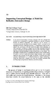
The concept of points of view allows to consider the different and possible perceptions that a designer can have of a product. A point of view is an abstraction through which an expert or a designer looks at a given product focusing on some aspects while at the same time ignoring others (Marino Drews, 1993). In this work, we consider, but not only, the structural, functional and geometrical points of view . The structural point of view describes the physical structure of the product giving its list of components. The functional point of view concerns the purposes or the objectives the product should accomplish. The designer can also describe the geometrical features of the product using the geometrical point of view. Other points of view as expressed by the different experts involved in the design process can also be defined if required. To illustrate these points of view see Figure I. Product
Polnl of \'ir,~W axis
BUi'lrd
I{c~ming
Sccllrlt}' base pOSi tionIng
Holding release block
Figure 1 Structural and functional points of view of a security clamping system for a snow-board.
A data structure for a generic design rrwdel
231
The properties of this concept are : the name of the point of view, the type (structural, functional, geometrical, etc.), and a property called "equivalence" allowing the definition, when it is possible, of a relationship between different points of view. The point of view concept has graph-based structure. In the structural point of view, the nodes represent the components of the product (part-of relationship). In the functional point of view, the nodes represent a top-down decomposition of the product objectives.
3
THE DESIGN PROCESS MODEL
This model describes the different phases of the product design and the actions made by the different participants in the process, be they machines or humans. Using this model, the designer can define the structure of the design process. Then, during the execution of this process, s/he will be able to specify all the information about the product being designed. Finally, s/he will be able to keep track of the process used in the design phase. The designer describes the process by mean of a task diagram (linear sequence, loops, nested sequences, etc.) high-lighting all the important phases of the design activity (Rieu et a!., 1994). SIRe has also the possibility to progressively build the design process by specifying the main tasks, which can be made step by step. The design tasks can be elementary tasks, i.e. not decomposable tasks and directly executable, or composite tasks. Because they exhibit a chain of execution tasks, the composite tasks are then decomposed in a task hierarchy. Chandrasekaran has defined design as a complex task which can be decomposed into sub-tasks, themselves decomposable or not into other sub-tasks (Chandrasekaran, 1990). Each process is then a set of linked design tasks able to be, themselves, composed of a set of elementary tasks. This chaining is dynamic in order to allow the description of structured, semi-structured and unstructured processes. According to Bussler (1993), a process is a structured process if the control flow between the process elements (tasks) is fully specified at specification time. A semi-structured process is a process where the control flow between the process elements is specified only for some of them. At last, an unstructured process is a process where process elements are specified without any control flow.
3.1
The "design-process" concept
This concept allows the description of the different tasks to be executed and their ordering for designing a given product. It specifies the first task and, in the case of semi-structured or unstructured processes, it gives the set of tasks that could occur in the design process. In this case of structured processes, the tasks control flow is included in the definition of the tasks themselves (See section 3.2). The properties of this concept are: the name of the design-process, the name of the designed product, the first task of the process, the list of the tasks that should be executed by the designer without any predefined control flow (this list highlights the undeterministic property of the design process), the times of the beginning and end of the design process.
3.2
The "task" concept
The task concept represents the execution of certain steps included in the design process. As indicated earlier, the design of a given product consists of the execution of a set of tasks with predefined control flow.
232
Part Eight Production Data Technology
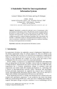
In the design process, the task is considered as an entity which allows the execution of a design step. In this process, a task could be represented alone or aggregated with other tasks in another process than the principal one, see Figure 2. These two types of tasks are also defined by Baldwin (1995) as terminal tasks (which is commonly called a tool invocation and represents a run of an application program) or abstract or nonterminal task (i.e. it is composed of other tasks). Process ~
Task
rl
Process
~--------~I ~~ r-~M~a~~ =-tic-a-~~c-I~ -m-~-l--'
.
Engincdirrensioning
~
0'-
p""'m>ter co~tio....
,...------, Tension decrease in
..... .....
the poles
Figure 2 Example of a synchronous electrical engine design process (Trichon, 1991). The task properties are: the name of the task, a "chaining" property to specify the name of the next task to be executed, a state graph corresponding to the execution steps of the task, the list of the tools executing this task, the programming code that the task may have. The controlflow operators: To allow the specification of the task control flow by the designer, we provide a set of control flow operators (sequence, parallel, conditional or stochastic choice, join, loop or back tracking structure) that determine the order in which design tasks in the design process must be executed. This set is not restrictive and can be extended to face special needs. To model these control flow operators, we need to define some task states in the process-state concept (See section 3.4.) like the start, finish, stop or wait states. This formalization is inspired from Bussler's work (Bussler, 1995). A language and a grammar have been defined for the description of the control flow structure using these operators, see Figure 3. An example of an integrated circuit design process is given in Figure 4 with the corresponding grammatical ex ression . Sequence (A, B) ::= start (A) ; If finish (A) = true Then start (B) Parallel (A, (B, C)) ::= start (A); If finish (A) = true Then start (B) and start (C)
Sequence
Parallel
ParallelJoin
Parallel-Join «A,B), C) ::= y : If finish (A) = true Then wait (finish (B) = true) Else IF fini sh (B ) = true Then wait (tinish (A) true) Else goto y; start (C) Fork (A, B" ... , Bnll ::= start (A) ; If finish (A) true Then start (Bil or ... start (Bn)
=
Fork
1
~ A
Fork
:
Bn
=
A data structure for a generic design model Cond-Fork
Cond-Fork (A, condl(Bt), ... , condn(B,» ::= start (A); If finish (A) = true Then Case ( cond I = true; strat (B t) ... condn = true; start (B,))
Cond-Fork -Join
Fork-Join «cond (A), B), C) ::= If finish (A) = true Then start (e) Else If finish (B) = true Then start (C)
Loop
Loop (A, cond (B), C) ::= When finish (A) = true If cond = false Then start (e) Else start (B) where e recedes A or e=A. Back-track (P, name) ::= save-context; start (P); If stop (P) = true Then restaure-old-context; start (P) where P can be a task or a sub-process. If it's a sub-process, then from any task it's possible to back-track and re-execute the rocess with the old context.
Back-track
Back·point =
233
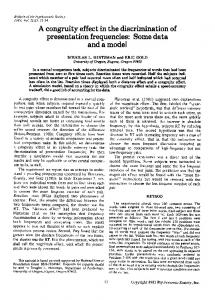
Figure 3 Task control flow operators where Begin and End are two tasks that respectively starts and finishes the design process but don't perform any action in opposition to the other tasks. Let P denote the principal process, Pi the different sub-processes, Bi the conditioned subprocesses (for i=l to n) and finally the task T represented by its behaviour. The control flow grammar is: P .. - Sequence (PI, P 2) / Parallel (PI, (P z, P3» / Parallel-Join «PI, P2), P 3) I Fork (PI, P 2, ... , Pn) / Cond-Fork (PI, B" B2, ... , Bn» I Cond-Fork-Join «B, P 2), P 3) / Loop (P, B, P) / Back-point (name P) / Back-track (name) / T B .. - cond (P) T .. - behaviour where behaviour represents the programming code and cond is a condition that should be verified. The control flow operators of the design process shows in Figure 4 are: (0) : sequence operator (I) : loop (verification, OK(net-list generation), circuit layout) (2) : loop (verification, OK(net-list generation), specification of the CDC) (3) : loop (optimal point search, OK(simulation), parameter definition support) (4) : loop (simulation, OK(results analysis), parameter definition support) (5) : loop (results analysis, OK(end), parameter definition support)
234
Part Eight Production Data Technology
~ lJow conrfal
....
.....
!lie gemuatlon
AutoCA 0 : 30 paCkage. OOKRS : OttjeCI·Oriented Knowledg
Rep,uenlalion
S~$18m
Smash : slmullllon paetcage
.... -
~ --
--
...
ano
,
(0)
pittameter d.fln_lIon ..... suppor t
t - - - -- - - - - - - - '
(OOI(RS)
Figure 4 Integrated circuit design process and the corresponding grammar for Figure 4 is: P ::= sequence (begin, PI) PI ::= sequence (specification of the CDC, P 2) P 2 ::= sequence (circuit layout, P3) P3 ::= cond-fork (verification, condl(P4), cond2(P s), OK(P6» P4 ::= loop (verification, OK(net-list generation), circuit layout) Ps ::= loop (verification, OK(net-list generation), specification of the CDC) P6 ::= sequence (net-list generation, P7) P7 ::= sequence (parametrisation, Ps) P 8 ::= cond-fork (optimal point search, Not-OK(P9), OK(P IO» P9 ::= loop (optimal point search, OK(simulation), parameter definition support) PIO ::= cond-fork (simulation, Not-OK(P II ), OK(P 12» P I1 ::= loop (simulation, OK(results analysis), parameter definition support) P I2 ::= cond-fork (results analysis, Not-OK(P I3 ), OK(end» P 13 ::= loop (results analysis, OK(end), parameter definition support).
3.3
The "design-tool" concept
This concept describes the set of tools used in the design process. These tools can be drawing software packages, calculation or estimation algorithms, simulation tools or 3D modelers, etc. The user must choose one or another of these tools regarding the functionalities offered. The properties of this concept are: the name of the design tool, a property called "functionality" which covers the set of functions that the tool provides, and a state describing the status of the given design tool: free, busy, etc.
3.4
The "process-state" concept
In this approach, we associate to each task a state-graph that keeps track of its execution steps. In fact, these graphs will not only inform about the state of the designed product (by giving
A data structure for a generic design nwdel
235
the list of parameters estimated or not by the task and the set of rules applied or not by this task) but also give information about the state of the design process itself (at a giving time, if a task has some problems to be performed, the design process will be suspended). The designer is free to consider only graphs corresponding to the most important tasks of his/her design process in order to prevent from a large and systematic save of all task graphs. Figure 5 shows the different states that a task can have during its execution (the graph has been inspired by the work of Bussler (1995) and Ceri et al. (1995».
Figure 5 Execution states of a task. Possible states of a task are: • ready: all the tasks which are ready to be executed by the processor are in this state, • running: a task which is currently executed by the processor is in this state, • stopped: when a task is in this state, this prevents the task from being processed further, • finished : tasks which are finished are in this state. We consider that a task can only be in one state in a given moment and transitions allow a task to pass from a state to another one. These transitions are: • start: this operation makes a task into the ready state where it waits for further processing, • stop: this operation stops a task from further processing, • resume : this operation puts back a task to the running state, • execute: this operation selects a task which is ready and processes it, • done : if all the data of the task are processed, then the task is finished itself. The properties of the "process-state" concept are: a state graph as mentioned above, a list of parameters obtained in the execution of the task which generates this state, and the rules fired or violated during the execution of the given task.
4
MODEL GENERICITY
To allow genericity for the design phase and to avoid any specialized model, only useful in specific cases, three conceptual representation levels for the two models have been introduced as described earlier, see Figure 6. Moreover, this genericity allows the reusability of models already defined and makes the design task easy and more simple to be performed. The first level is a meta-level where all the necessary concepts establishing the architecture of the two models are defined. At this level, all the properties relatives to each concept are defined in order to be valuated in the specification level. The second level, or specification-level, is used to specify the design process. Starting from the concepts defined in the previous level (meta-level), the designer writes down the product model for the product to
236
Part Eight Production Data Technology
be designed. Then, he defines the different design tasks and figures out the design tools involved in the execution of each task and finally orders them by defining a control flow using the set of operators presented earlier. The third level, or instantiation-level, concerns the activation or enactment of the design process for a given product instance as defined in the specification level. Regarding the type of product to be designed, the designer selects a design procedure from the specification level to help him in hisdesign task. He must not necessarily follow this procedure step by step but can change it by including his own specifications. He can also decide to include these specifications in the existing design procedure or to create a new design procedure. Mct .. ·Oe«lJn·TIK.1 M(I~ ' P'Lld u~t · P:l.t:llnC" (Cf~
c=::;:::.
MC't;a- Dc.slln- Pr, ,,"c~5
c=::;:::.
c=::;:::.
~~~~~~~~~~~~~~==MC~~~'P~~="b="='C~;~CW~~
L-
______________~ Tlrt: SpUifit:iltrOI1 Le vel
In~t tl llc:i3t1 0n link
Control Flow hnk
_-:
..... .. ----_ ...
-_ ..
Figure 6 The three conceptual levels of the models.
5
CONCLUSION
The generic models presented in this paper are the result of a deep analysis of existing models dedicated to integrated design for CAD such as DaMoCLES (Trichon, 1991) and DEKLARE (Saucier et aI. , 1995) and (Vargas et aI., 1994). By introducing the product model, we allow the description of the designed product under different points of view by which the product can be perceived. Using the design process model, the representation of the design process in an incremental way is made possible. This is also accomplished giving the genericity of the two models. These models are under implementation and they will certainly evolve but we believe that they represent the minimal template set for a model dedicated to the development of new applications for integrated design.
A Mta structure for a generic design nwdel 6
237
REFERENCES
Baldwin, A.A., Chung, MJ. (1995) A Formal Approach to Managing Design Processes, Computer, February, 54-63. Bussler, C. (1993) Entreprise Process Integration Model and Infrastructure, in Information Infrastructure Systems for Manufacturing, North-Holland, Amsterdam, pp.159-170. Bussler, C. (1995) Workflow-Management-Systems as Enterprise Engineering Tools, Working Conference on Modelling and Methodologies for Enterprise Integration, Heron Island, Queensland, Australia, 8-10 November. Ceri, S. et al. (1995) Conceptual Modelling of Workflows, Research Report, Politecnico di Milano, Italy. Chandrasekaran, B. (1990) Design Problem Solving: A task Analysis, AI Magazine, Winter. Chen, Y.T., Kusiak, A. (1994) An Object-Oriented Approach to Design of Process Parameters, in Modem Manufacturing: Information Control and Technology, SpringerVerlag, Berlin, pp. 115-131. Marino Drews, Olga. (1993) Raisonnement cIassificatoire dans une representation it objets multi-points de vue, PhD thesis, Universite Joseph Fourier, Grenoble, France. Oquendo, F. and Arbaoui, S. (1991) OU en est la modelisation du processus de production du logicie1 ?, Proceedings of the 4th International Conference on Software Engineering and its Applications, Toulouse, France. Rieu, D.et al. (1994) Conception integree des liaisons mecaniques, IFIP Conference Features Modeling and Recognition for Advanced CAD/CAM Systems, Valenciennes, France. Saucier, A. et. al. (1995) Ingenierie d'aide it la conception : un environnement pour la realisation d'un systeme d'aide it la conception d'organes mecaniques, MICAD, Paris, France. Scapin, L. et al. (1989) Un outil d'acquisition et de representation des taches oriente-objet, INRIA Research Report N D .l063, France. SMECI (1991) Manuel de l'utilisateur, Version 1.5, ILOG, France. Takeda, H. et al. (1990) Modeling Design Processes, AI Magazine, Winter 1990, 37-48. Trichon, F. (1991) Modelisation du processus de conception des machines electriques, Ie systeme expert DaMoCLES, PhD Thesis, LEG-INP Grenoble, France. Vargas, C. et al. (1994) Knowledge modelisation and constraint propagation in a computer aided design system, CoPiCAD 94 workshop "Application of Constraint Processing in CAD", Lausanne, Switzerland, August. Willamowski, J. (1994) Modelisation de taches pour la resolution de problemes en cooperation systeme-utilisateur, PhD Thesis, Universite Joseph Fourier, Grenoble, France.
238
Part Eight Production Data Technology
Biographie Yasmina HARANI is a Ph.D. student of the Departement of Industrial Ingineering at the Polytechnical National Institut of Grenoble, France. She got her Engineer degree in computer science from the Computer Science National Institut of Algiers, Algeria in 1992. Currently, she is working on her Ph.D. degree with Pr. Vernadat. Her research interests include design process and product modeling and definition, concurrent engineering within the area of integration in Computer Aided Design systems, knowledge representation, engineering design and manufacturing, Artificial Intelligence, CIM and formal description techniques. Franfois VERNADAT is a French and Canadian citizen. He got his Master degree in Electronics and Automatic Control in 1977 and the Ph.D. degree in 1981 from the University of Clermont, France. From 1981 till 1988, he has been a researcher officer at the Division of Electrical Engineering of the National Research Council of Canada, Ottawa, Ont. In 1988, he joined INRIA, a french research institut in computer science and automatic control. He is currently a professor at University of Metz, France. His research interests include CIM, database technology and information systems, enterprise modeling and integration, knowledge representation, formal description techniques, Petri nets, and model enactment. Beside his work on the M* methodology for CIM information systems, he has headed the development of a main-memory database system (DBSIR), and was one of the chief architects of CIMOSA, an Open System Architecture for CIM initially developed as an ESPRIT project (AMICE). He has authored and co-authored over 95 scientific papers in journals, conferences, and books. He is the co-editor of the books "Advanced in Factories of the Future, CIM and Robotics" (Elsevier), and "Practice of Petri nets in Manufacturing" (Chapman & Hall). He is the European editor for the International Journal of CIM. Pro Vernadat is a member of the IEEE Computer Society, ACM, and SME.