N90-27313 A
Diagnosis
Object-Oriented
NASA
David L. Iverson Ames Research
System Fault
and Center
Using Tree
Models
F.A. Patterson-Hine Ames Research Center Mail Stop 244-4 Moffett Field, CA 94035
[email protected]
NASA
Mail Stop 244-4 Moffett Field, CA 94035
[email protected]
Abstract Spaceborne computing systems must provide reliable, continuous operation for extended periods. Due to weight, power, and volume constraints, these systems must manage resources very effectively. A fault diagnosis algorithm is described which enables fast and flexible diagnoses in the dynamic distributed computing environments planned for future space missions. The algorithm uses a knowledge base that is easily changed and updated to reflect current system status. Augmented fault trees represented in an object-oriented form provide deep system knowledge that is easy to access and revise as a system changes. Given such a fault tree, a set of failure events that have occurred, and a set of failure events that have not occurred, this diagnosis system uses forward and backward chaining to propagate causal and temporal information about other failure events in the system being diagnosed. Once the system has established temporal and causal constraints, it reasons backward from heuristically selected failure events to find a set of basic failure events which are a likely cause of the occurrence of the top failure event in the fault tree. The diagnosis system has been implemented in Common LISP using Flavors. Introduction Most artificial intelligence diagnosis systems developed to date fall into one of two categories: rule-based systems or model-based systems. Rule-based systems, such as MYCIN [1], encode expert knowledge about the diagnosis problem as declarative rules. These systems have been quite successful, but it is difficult to maintain consistency when updating or adding to the rulebase of such systems. Model-based diagnosis systems usually simulate the system being diagnosed and find faults by comparing the simulation results with actual data. The simulations are usually quite slow and the diagnosis problem could become quite complex when multiple faults are present. When a diagnosis system is used in a dynamic environment, such as the distributed computer system planned for use on Space Station Freedom, it must execute quickly and its knowledge base must be easily updated. Representing system knowledge as object-oriented fault trees provides both features. Changing values in these fault trees is easily accomplished by changing an object's instance variables and using well defined procedures to update related information in the fault tree. Also, reasoning based on knowledge represented in a fault tree is faster than running a system simulation and comparing results. The diagnosis system described here performs its task by reasoning with knowledge contained in an object-oriented fault tree. It is well suited for use in a changing environment since a fault tree can be updated during normal operation so that it accurately reflects the current system status. When a fault occurs, the diagnosis system will have up-to-date information for performing its task.
341
J
Object-Oriented
Fault
Tree
Representation
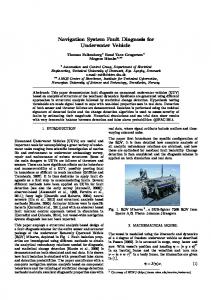
Fault tree analysis can be described as an analytical technique where an undesired state of a system is specified and the system is analyzed, in the context of its environment, to find all tenable ways this undesired state could occur. The resulting information can be represented as a tree structure with the original undesired event (or failure) at the root, the possible causes of that event as the root's children, the causes of those events as their children, and so on. Analysis stops at any given branch of the tree when the event described by the leaf node is fine-grained enough to satisfy the needs of the analyzer. These leaf nodes are called basic events and frequently correspond to failures which are relatively easy to repair or overcome. All non-leaf nodes of a basic fault tree can be thought of as logic gates representing a logical AND or OR. An AND gate signifies that all the child events of that node must occur before the event represented by the node will occur. An OR gate means if at least one of the child events occurs, the parent event will occur. Sometimes a NOP gate is used when a node has only one child. A NOP gate is just like an OR gate with only one child event. See Fig. 1 for illustrations of fault tree AND and OR gates. Fig. 4 shows a complete fault tree. All power is failed
is failed
is failed
is failed
An AND gate
closed I failed Valve is
, l ware Va,failure eard-
, human error
[ alve c,osed for testing JI
An OR gate
Figure 1: Examples of Fault Tree gates (From the Fault Tree Handbook [4]) Frequently other information will be associated with each fault tree node. might also contain the probability of occurrence of its associated failure event, between the occurrence of a child event and the occurrence of its parent event. fault tree is called an augmented fault tree [2].
For instance, a node or how long it takes In these cases, the
Patterson-Hine [3] has developed an efficient object-oriented fault tree representation and an evaluation procedure which permits dynamic updating and rapid recalculation of values associated with fault tree events. In this representation, each event node in a fault tree is described by an
342
object with instance variables other details about the failure
containing information about the node's event represented by that node.
parents,
children,
type, ant
The information in the fault trees used by the diagnosis system includes event importances, C-factors and time intervals. The importance of an event is a measure of how critical that event is to the occurrence of the top event of the fault tree. It reflects the relative contribution of that event and all events in the subtree below it to the occurrence of the top event in the fault tree. The Cfactor associated with a failure event in a fault tree is a heuristic measure of the likelihood that the occurrence of the parent fault of that event was caused by that event rather than by one of its siblings. The time interval of an event under an OR gate is an estimate of how much time will elapse from the moment that failure event occurs until its parent failure event occurs. In the case of a child event under an AND gate, the time interval measures the time between the moment when all of the child events have occurred and the occurrence of the parent event. The top event (root node) of a fault tree does not have values for importance or C-factor. See Fig. 2 for an illustration of some of the objects in an object oriented representation of the fault tree nodes shown in Fig. 1.
Came:
P1
Event: Importance: C-factor: Time Int.: Parent: Children: Type:
All Power is Failed 0.42 100 0.8 E1 G1, G2, B1 AND-Gate
Game: Event:
V2 Valve failed closed
Importance: C-factor: Time Int.: Parent: Children: Type:
0.31 24 1.2 V1 VHW, VHE, VCT OR-Gate
fName: Event: Importance: C-factor: Time Int.: Parent: Type: J
G2 Gen. 2 is failed 0.74 100 2.1 P1 Leaf-Node
_ tName: Event: Importance: C-factor: Time Int.: Parent: Type:
J VHW Valve H/W failure 0.82 47 0.9 V2 Leaf-Node
Figure 2: Fault Tree Object Representation In a dynamic environment, such as a distributed computer system, the probability of occurrence or the importance of a given event may change as the system is reconfigured. Objectoriented representation of the fault tree allows these changes to be made easily and their consequences to be calculated quickly. More traditional knowledge representations, such as if-then rules, do not facilitate updates nearly as well.
The
Diagnosis
Algorithm
This diagnosis system is based on the failure cause identification phase of the diagnostic system described by Narayanan and Viswanadham [2]. Their system has been enhanced in this implementation by replacing the knowledge base of if-then rules with the object-oriented fault tree representation. This allows the system to perform its task much faster and facilitates dynamic updating of the knowledge base. Accessing the information contained in the objects is more
343
efficient than performing a lookup object-oriented fault tree evaluation
operation algorithm
on an indexed rule base. makes dynamic updating
Also, Patterson-Hine's viable.
The diagnosis system is given information about the system being diagnosed in the form of alarms. Alarms can be thought of as lights on a panel monitoring the system. A normal alarm is a green light on the panel that indicates the failure event it is monitoring has not occurred. An abnormal alarm is a red light on the panel indicating that the failure event has occurred. Each possible alarm corresponds to a node in the fault tree. If it is known that the failure event represented by a node has not occurred, that event is placed in the normal alarms set. If it is known that an event has occurred, that event is placed in the abnormal alarms set. Any information about which failure events have and have not occurred is very helpful for diagnosis and can speed up the diagnosis process considerably. The diagnoses produced by this system are sets of basic failure events that causally explain the occurrence of the top failure event. The diagnosis process is initiated by specifying the failure to be diagnosed, the estimated time of occurrence of this failure, the current set of normal alarms and the time that each normal alarm was last confirmed, a set of abnormal alarms with estimated failure times, and the root node of the fault tree representing the system to be diagnosed. The diagnosis begins by inferring all failure events that must have occurred and those that could not have occurred based on the information in the normal and abnormal alarm sets. The alarm sets are updated accordingly. The system uses the alarm sets to guide its search of the diagnosis space. It does not consider those portions of the diagnosis space with diagnoses containing sets of basic failure events that would cause the occurrence of a failure in the normal alarms set. Also, those portions of the search space with diagnoses containing abnormal alarms are searched early in the diagnosis process. The system also checks possible diagnoses for temporal and causal consistency. The time of occurrence information provided for each alarm is used to propagate temporal constraints throughout the fault tree. In order for a diagnosis to be accepted, the occurrence times of the suspected failure events must have a logical causal ordering. In reference 2, Narayanan and Viswanadham give a thorough explanation of the use of temporal constraints. While it is updating the alarm sets, the system builds a set of starting points corresponding some of the confirmed failure events. The starting points are chosen in such a way that the combined diagnoses of the events in the starting failures set will be sufficient to explain the occurrence of the top level failure event.
to
Finally, the system performs backward chaining from the selected starting points to find a set of basic events that were a likely cause of the top failure event. The backward reasoning process first decomposes the starting point failures into sub-failures. Then the sub-failures are further decomposed. At each decomposition, a set of heuristics is used to choose which branches of the fault tree are likely to produce a good diagnosis. The heuristics make decisions based on the contents of the alarm sets, the temporal information associated with the events, the overall importance of each failure event, and the C-factors of the events. This decomposition process continues until basic faults are reached. If the basic faults in the proposed diagnosis do not violate any temporal or causal constraints, they are returned as a diagnosis for the top failure event. If any constraints are violated, the algorithm backtracks and searches other branches of the fault tree for possible diagnoses. The basic algorithm and heuristic descriptions can be found in Narayanan and Viswanadham [2]. This implementation has modified those algorithms to use the object-oriented fault tree knowledge representation instead of the rules suggested by Narayanan and Viswanadham, but the basic diagnostic procedures are the same as those stated in that paper.
344
Diagnosis
Examples
The following examples show diagnoses of the simple adder circuit shown in Fig. 3. The top level failure event for the adder fault tree (see Fig. 4) is incorrect adder output. In this tree all
4
! 2 Port Numbers Figure 3: Simple Adder Circuit basic events are seen as equally important (if any failure occurs, the system fails), and the fault propagation time intervals are all the same except for operator input error. Also, the contribution of a failed gate was heuristically judged to be slightly more important than the contribution of errors propagated from other sources in the circuit (hence the higher C-factor). This loosely accounts for facts such as if one input to an AND gate is zero, the validity of the other input is irrelevant. This also results in diagnoses favoring gates nearer to the circuit output. Note that the diagnosis system does not always return all possible causative faults for the top level failure, just those that seem very likely. Example 1: (f'md-failures '(incorrect-result adder) ; Top Level Event w/ 1 ; Time of Occurrence '(((incorrect-operator-input adder) 1) ; Normal Alarms ((incorrect-port-input adder port 1) 1) ((incorrect-port-input adder port2) 1) ((incorrect-port-input adder port3) 1)
)
Diagnosis:
'(((incorrect-port-output 'adder)
adder
port4)
(((FAULTY-GATE
X2) 0.96))
.98)) ;Abnormal Alarm ; Root of Fault
Tree
The top event is an incorrect adder result. The normal alarms set indicates that the operator input was correct and arrived at the input ports without any problems. The abnormal alarms set reports that we discovered an incorrect output value on port four 0.02 seconds before diagnosis began. The diagnosis is that Gate X2 is faulty since it connects directly to output port 4 and, due 345
to the C-factors,gatefailure is morelikely tocausebadoutputthanpropagatederrors. The numbersincludedin thediagnosesarethelatesttimesthatthe suspectfaultscould haveoccurredin orderto causethe top level failure. Example2: (find-failures'(incorrect-resultadder) ; Top Level Event w/ 1 ; Time of Occurrence '(((incorrect-operator-input adder)1) ; Normal Alarms ((incorrect-port-inputadderportl) 1) ((incorrect-port-inputadderport2) 1) ((incorrect-port-inputadderport3) 1) ((faulty-gateX2) 0.96) ) '(((incorrect-port-output ((incorrect-port-input 'adder)
Diagnosis:
(((FAULTY-GATE
adder port4) .98) ;Abnormal Alarms O 1 Port2) .97)) ; Root of Fault Tree
A 1) 0.95)
((FAULTY-GATE
X 1) 0.94))
This is like Example 1, but (Faulty-Gate X2) has been added to the set of normal alarms, indicating that the X2 failure did not occur, and the failure event (incorrect-port-input O1 Port2) was added to the abnormal alarms list. Having X2 in normal alarms sent the system a little deeper into the fault tree to find that gate X1, which feeds through X2 out to port 4, was faulty. (FaultyGate A1) was also added to the diagnosis to account for the incorrect input to gate O1.
Conclusions This diagnosis system based on fault tree models has several advantages over other diagnosis systems. It does not rely on a single fault assumption in its reasoning. In fact, most diagnoses will include many basic faults. It deals with temporal parameters and uses them to effectively reduce the diagnosis search space. Probabilistic reasoning is used to a certain extent in selecting rules and search paths. The inclusion of event importance factors allows the system to consider the most heavily weighted search paths first. The use of C-factors includes some expert knowledge in the diagnosis procedure. The diagnosis technique is not domain specific. If a fault tree can be constructed for a given system, this diagnoser can diagnose that system. One shortcoming of this system is that the diagnosis is only as good as the fault tree model. If an incomplete, undetailed, or inaccurate fault tree is given to this system, the resulting diagnoses will be equivalently incomplete, undetailed, and inaccurate. This is in contrast to a diagnoser which models the system as a simulation. The trade off here is that the simulation model will probably be domain specific and incapable of expressing as rich a diagnosis environment as a fault tree. Also, the simulations would have difficulty including probabilistic and heuristic knowledge in their diagnosis, and diagnosis using simulation is usually quite slow.
Future
Work
There are plans to integrate this diagnosis system into a fault tolerant distributed system. The overall goal of this work is to reduce the amount of redundancy needed for fault tolerant spaceborne computation. Distributed systems, such as those planned for Space Station Freedom, will be characterized with fault trees and Markov diagrams. As the distributed system runs, the 346
system knowledge base will be updated to reflect the current status of the system. When faults are detected during execution, the diagnosis system will be used to determine the basic causes of the faults. Then the system load will be redistributed to avoid the faulty components and the computation will continue. This work will be done on the advanced architecture testbed and fault tolerant computing testbed at NASA-Ames Research Center.
347
o.
f _f
B o. Y,
._
._E