132
IEEE TRANSACTIONS ON INDUSTRIAL ELECTRONICS, VOL. 52, NO. 1, FEBRUARY 2005
A Different Approach to Implement an Active Input Current Shaper Nimrod Vázquez, Member, IEEE, Josué López, Jaime Arau, Senior Member, IEEE, Claudia Hernández, Member, IEEE, and Elías Rodríguez
Abstract—In recent years, several ac/dc converters have been presented in order to meet the power quality regulations, while maintaining the lowest number of components with the purpose of minimizing the cost and complexity; for this purpose the active input current shaping technique was proposed. In this paper a new active input current shaper (AICS) is presented. Differently from the traditional series AICS, the proposed scheme connects the auxiliary output of the main converter in parallel with the rectified ac mains instead of the series connection. The proposed parallel scheme demands a current with a low harmonic content where the standard specifications are fulfilled. The operation, simulation, and experimental results of the proposed scheme are presented. Index Terms—Active, power-factor correction, power processing, regulators, shaping.
I. INTRODUCTION
S
EVERAL topologies have been recently proposed in order to find an ac/dc converter with high efficiency, small size, and fast regulation of the output voltage, complying with harmonic standard specifications [1]–[10]. In order to obtain the lowest cost possible, different techniques have been proposed. An option to obtain good efficiency and fast regulation, as well as complying with standard specifications is to use the active input current shaping technique [1]–[8]. The active input current-shaping technique consists of one converter with two outputs: the main output is used to feed the load, and the auxiliary output is used to shape the input current [Fig. 1(a)]. Traditionally, the auxiliary output is connected in series with the rectified ac mains; this topology has been studied extensively in the literature, and many variations have been proposed [5]–[8]. In this paper a new active input current shaper (AICS) is presented, which is the parallel scheme. The proposed scheme consists of one converter with two outputs: the main output feeds the
Manuscript received December 27, 2003; revised February 3, 2004. Abstract published on the Internet November 10, 2004. This paper was presented at the 2002 IEEE Power Electronics Specialist Conference, Queensland, Australia, June 23–27. N. Vázquez, C. Hernández, and E. Rodríguez are with the Electronics Engineering Department, Instituto Tecnológico de Celaya, 38010 Celaya, México (e-mail:
[email protected];
[email protected];
[email protected]). J. López was with the Electronics Engineering Department, Centro Nacional de Investigacion y Desarrollo Tecnologico (CENIDET), 62490 Cuernavaca, México. He is now with Electromag S. A. de C. V., México City, México (e-mail:
[email protected]). J. Arau is with the Electronics Engineering Department, Centro Nacional de Investigacion y Desarrollo Tecnologico (CENIDET), 62490 Cuernavaca, México (e-mail:
[email protected]). Digital Object Identifier 10.1109/TIE.2004.841101
Fig. 1. Traditional active input current shaper. (a) Scheme. (b) Typical circuit. (c) Simplified circuit.
load, and the auxiliary output shapes the input current; however, the auxiliary output is connected in parallel with the rectified ac mains [Fig. 2(a)]. The proposed parallel scheme can be extrapolated to many variations as there are with the series scheme, and some of them will be mentioned. In Section II the proposed parallel AICS is described and analyzed. In Section III the power processing of the AICS is discussed. In Section IV the experimental results are presented. Finally, the conclusions are duscussed in Section V. II. PROPOSED AICS In order to understand the proposed scheme, first, a brief analysis of the series AICS will be discussed. A simple configuration of the series AICS is shown in Fig. 1(b). The main output
0278-0046/$20.00 © 2005 IEEE
VÁZQUEZ et al.: DIFFERENT APPROACH TO IMPLEMENT AN ACTIVE INPUT CURRENT SHAPER
Fig. 3.
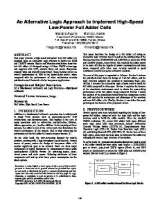
Fig. 2. Parallel active input current shaper. (a) Scheme. (b) Simplified circuit. (c) Proposed circuit.
operates as a flyback converter output and the auxiliary output operates as a forward converter output. To understand the shaping technique, the auxiliary output is modeled as a pulsating voltage source and the diode full bridge [see Fig. 1(c)]. The series AICS is represented by a diode operates as follows. • If the rectified ac mains voltage is higher than the capacitor voltage minus the pulsating voltage source , then diode conducts and, therefore, the inductor is charged. • If the rectified ac mains voltage is lower than the capacitor voltage minus the pulsating voltage source , then the inductor is discharging or with zero current if even there is not stored energy on it. • The two preceding steps occur at the switching frequency. With this technique the diode full bridge is obligated to conduct moreofthetimethatthetraditionaloneplusabulkycapacitor.This permits the harmonic content of the line current to become lower, so standard specifications like IEC-61000-3-2 are fulfilled. To understand the proposed parallel scheme, the auxiliary output is modeled as a pulsating voltage source, but a diode is connected in series with this voltage source [Fig. 2(b)], and, . It is also, the diode full bridge is modeled as a diode important to note that, even for modeling purposes, a diode is added, and the final circuit has less semiconductors than the series AICS. The parallel AICS operates as follows. • If the pulsating voltage source is higher than the rectified ac mains voltage and also higher than the bulky ca-
133
Current of the inductor L , illustrating its conduction modes.
is not conducting pacitor voltage , then the diode is conducting. As a consequence, the inand the diode is charged . ductor • If the pulsating voltage source is lower than the rectified ac is discharged mains voltage, then the inductor . The diode is conducting and the diode is not. • The two preceding steps occur at the switching frequency. With this operation form the diode full bridge is obligated to conduct for a similar time as the series AICS. This permits standard specifications like IEC-61000-3-2 to be easily fulfilled. The proposed parallel AICS circuit is shown in Fig. 2(c). For the main output a flyback converter operating in discontinuous conduction mode (DCM) is used, and to generate the pulsating voltage source an extra winding is added to the transformer (the auxiliary output). A small inductor was added to the pulsating to voltage source to permit the diode full bridge and diode start and finish to conduct at zero current. A. Operation Stages of the Proposed AICS The input inductor determines the operation of the converter; this inductor is operating in DCM around the zero crossing of the ac mains and it is operating in continuous conduction mode (CCM) the remaining time. This is illustrated in Fig. 3, however, for illustrative purposes the current ripple does not correspond with actual circuit. Due to the conduction mode of the inductor , the proposed converter has different stages that depend on the turn-on time, switching frequency, and the small inductor added to the pul. The converter waveforms are shown sating voltage source in Fig. 4. In the figure the amount of time between the stages does not correspond to the actual circuit (this was made solely for illustrative purposes). The stages are as follows. Stage 1: This starts when the switch is turned on. The transis charged with the bulky capacitor former primary winding is increased. In voltage, so the transformer primary current this stage the polarity of the auxiliary output voltage permits the to conduce; then the inductor increases its current diode until it reaches the current of the inductor ; also, the is decreased until it reaches zero current, rectified current where, at this moment, this stage finishes. When the inductor is operating in DCM this stage does not exist. Stage 2: In this stage the current of the inductors and is the same, because the diode full bridge is not conducting. The transformer primary windinghas been charged and, also, through
134
IEEE TRANSACTIONS ON INDUSTRIAL ELECTRONICS, VOL. 52, NO. 1, FEBRUARY 2005
there exists an effect produced by the current of the transformer to the transformer secondary current . auxiliary winding is transThis is because the energy stored in the inductor ferred to the main output. This effect is due to the existence of the inductor . current follows the Stage 4: In this stage the inductor form of the rectified ac mains. The transformer auxiliary winding is not working. The main output operates as a typical flyback converter output, then the energy previously stored by the transformer primary winding is delivered to the output. This stage finishes when the remaining energy of the transformer is delivered to the load; this occurs when the transformer secondary current reaches zero current. is still delivering enStage 5: In this stage the inductor is in CCM, ergy to the bulky capacitor . If the inductor the stage will finish when the switch is turned on, but if the inis in DCM, the stage will finish when the inductor is ductor completely discharged. is in DCM does this Stage 6: Only when the inductor stage occur. This stage starts when the inductor is completely discharged, and finishes when the switch is turned on. To assure the proper operation of the converter, some relationships between the ratios of the transformer windings are considered (1) (2) where turns number of the transformer auxiliary winding; turns number of the transformer primary winding; turns number of the transformer secondary winding. The condition (1) must be fulfilled to assure that the inductor will be charged properly. The condition (2) is not strictly required, but should be near to one in order to avoid a high current stress in the transformer secondary; the high current stress is due to the coupling effect discussed in Stage 3 of the converter operation. B. Steady-State Analysis Fig. 4. DCM.
Waveforms of the proposed parallel AICS for L in (a) CCM and (b)
the auxiliary output is delivered energy; then, the transformer priareincreased.Atthis marycurrent andtheinductorcurrent time the auxiliary output is working as a forward converter output. This stage finishes when the switch is turned off. Stage 3: When the switch is turned off all the transformer windings change theirs polarity, therefore, the stored energy on the transformer primary winding is delivered through the transformer secondary winding to the main output, so the transformer is decreased. The transformer auxiliary secondary current output also changes its polarity, making the current through the starts to decrease until it reaches zero current. At inductor the same time the diode full bridge starts to conduct, then the is increased until it reaches the inductor rectifier current current; at this moment this stage finishes. As the transformer auxiliary winding and the transformer secondary winding are magnetically coupled, during this stage
The steady-state analysis of the converter determines the operation of the converter at low frequency; this analysis is helpful in designing the converter in order to comply with the standard specifications. The analysis presented here is made considering the concept of the loss-free resistor discussed in [3]. The inductor operates in DCM and CCM as shown in Fig. 3. The inductor current in DCM is near zero, and solely for analysis purposes it will be neglected. The equivalent circuit to analyze the input stage of the converter is as shown in Fig. 5(a). The converter works as a modified forward converter, because an extra inductor is added and the rectified ac mains to the forward converter; the is considered much lower than . inductor The waveforms of the modified forward converter operating to in CCM are shown in Fig. 5(b). Considering the ripple on the following is obtained: be negligible and analyzing for (3) where
is the switching frequency.
VÁZQUEZ et al.: DIFFERENT APPROACH TO IMPLEMENT AN ACTIVE INPUT CURRENT SHAPER
135
in DCM is considered zero, the boundary between the DCM and CCM is obtained from (7) with the condition (8) The angle between the boundary conduction duction angle (Fig. 3) are obtained from (8)
and the con-
(9) (10) where is the peak of the rectified ac mains. Equation (10) is important in designing the proposed converter, because the conduction angle determines whether the converter will comply with the standard specifications [4]. As the rectifier only operates at the turn-off time of the switch (Fig. 5), the average input current can be approximated as (11) The energy balance of the converter is
(12)
Fig. 5. Simplified circuit that represents the input stage. (a) Circuit. (b) Waveforms.
where is the output power and is the efficiency of the proposed converter. and (11) in (12), then evaluSubstituting ating the integral the following is obtained:
From the figure, it can be observed that (4) The average output voltage of the modified forward converter (13)
is (5)
Using (10) and (13) it is obtained that
Substituting (3) and (4) in (5) it is obtained that
(14) (6)
is the loss-free resistor. where Therefore, from (6) the current form of the inductor CCM is obtained
in
(7) is the rectified ac mains. where in As can be observed in (7) the current of the inductor CCM follows the form of the rectified ac mains. As the current
With (14) the loss-free resistor can be estimated and, therefore, the inductance for a desired conduction angle which permits us to fulfill the standard specifications. With (10) the ratio for the transformer auxiliary winding with respect to the transformer primary winding can be obtained for the and conduction angle. desired bulky capacitor voltage C. Features of the Converter Important features of the converter are the stress of the power transistor, the voltage on the bulky capacitor, the electromagnetic interference (EMI), the efficiency, and transformer and inductors sizes. In this section thrse features are discussed and also
136
IEEE TRANSACTIONS ON INDUSTRIAL ELECTRONICS, VOL. 52, NO. 1, FEBRUARY 2005
compared briefly with the series AICS; in fact, the proposed parallel AICS has some differences and similarities with the series AICS. The two AICS have the same voltage stress at the power transistor determined by (15) Also, the efficiency is similar in both converters; the efficiency is shown in Section IV. According to [3], the bulky capacitor voltage of the proposed converter is similar to the delayed series AICS; the bulky capacitor voltage is shown in Section IV; the capacitor voltage is low, even for light loads. Some of the differences are the EMI, inductor , inductor , the transformer size, and the semiconductors. The parallel AICS requires an EMI filter, this is due to the current demanded at the rectified ac mains (Fig. 5); this EMI filter must be at the ac side, because if it is placed at the dc side it will interfere with the converter operation. The transformer size is almost the same for both AICS; this is because the power recycled in order to fill the standard specifications is the same, and then the handled power is almost the same; however, the auxiliary winding of the parallel AICS has more turns than the series scheme, and this factor must be considered in the transformer selection. According to and the design procedure discussed in [3], the inductors for the series AICS has a value determined for the loss-free re. The loss-free resistor for the parallel AICS is lower sistor than the series scheme, resulting in a lower inductance value and, therefore, a size reduction. The parallel AICS has one less diode compared to the series scheme.
Fig. 6. Parallel AICS with autotransformer.
Fig. 7. Power flow representation for AICS schemes.
From (16) is obtained the efficiency of the complete converter, which is (17) As can be observed in (17) the efficiency is penalized due to the percentage of recycled energy . The percentage must be minimized as much possible, in order to increase the efficiency of the converter, which represents a lower power processing. The recycled power for the proposed AICS depends on the transformer auxiliary output, the duty cycle, and the current of the inductor . The recycled power is
D. Variations of the Proposed Converter Many variations of the series AICS have been reported in the literature [5]–[8]. These variations can also be implemented in the parallel scheme. An autotransformer can be used instead of an extra winding (Fig. 6); or, instead of a flyback converter as the main converter, a forward converter or a converter with a symmetrically driven transformer can be used; this last option is to increase the switching frequency and obtain a small converter like in [5].
III. POWER PROCESSING IN AICS SCHEMES All the AICSs handle more power than a standard converter. Sometimes it is said of this kind of converter that it processes the power only once, which is of no consequence to the efficiency; however, this is not true, as it will be shown in this section. The auxiliary output recycles an amount of power as illustrated in the power flow diagram of Fig. 7. From this figure it is obtained that (16) where Recycled power the percentage of the power processed.
Input power is
(18)
With (13) and (18) the percentage is obtained
for the proposed AICS
(19) As can be observed in (17) and (19) the efficiency depends on the percentage , and depends on the duty cycle, the ratio of the transformer windings, and the conduction angle. Therefore, it is important to note that there is a relationship between the efficiency and the conduction angle ; this angle determines whether the converter will meet the standard specifications. IV. EXPERIMENTAL RESULTS The converter was designed with the following parameters: W, V and V . The parameters mH, H, and F. The obtained are converter was designed to fulfill IEC 61000-3-2 class D, since this is more restrictive than class A; however, it is important to mention that the limits were extrapolated to the input voltage used.
VÁZQUEZ et al.: DIFFERENT APPROACH TO IMPLEMENT AN ACTIVE INPUT CURRENT SHAPER
137
Fig. 8. Proposed AICS at P = 50 W: ac mains voltage, ac mains current. (CH1: 1 A/div, CH2: 50 V/div).
Fig. 10.
Efficiency and bulky capacitor voltage of the proposed AICS.
Fig. 9. Proposed AICS under load variation. Top to bottom: output voltage, output current, input current (CH1: 10 V/div; R3: 0.5 A/div; R2: 1 A/div).
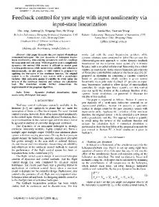
The experimental results are shown in Figs. 8–11. In Fig. 8 the ac mains voltage and current are shown at full load. In Fig. 9 the performance of the converter under load variation is shown,; as can be observed a fast dynamic response is obtained. In Fig. 10 the efficiency and bulky capacitor voltage of the converter are graphed. The harmonic content of the input current is shown in Fig. 11; as can be observed the standard specification IEC 61000-3-2 class D is fulfilled. V. CONCLUSION In this paper a new AICS, the parallel scheme, has been presented. Differently from the traditional series AICS, the proposed scheme connects the auxiliary output in parallel to the rectified ac mains instead of the series connection.
Fig. 11. Harmonic content of the proposed AICS versus the standard IEC 61000-3-2.
The proposed parallel scheme demands a current with a low harmonic content so that the standard specifications are easily fulfilled. The proposed parallel scheme has some differences and similarities in comparison witrh the series scheme. The parallel scheme can be extrapolated to all variations reported in the literature for the series scheme. In this paper the autotransformer option was illustrated.
138
IEEE TRANSACTIONS ON INDUSTRIAL ELECTRONICS, VOL. 52, NO. 1, FEBRUARY 2005
The operation, analysis, and experimental results of the proposed scheme were presented. Also, a power processing analysis was made for the AICS, which illustrated the way of kind of converter processes the power.
REFERENCES [1] L. Huber and M. M. Jovanovic, “Single-stage single-switch isolated power supply technique with input current shaping an fast output-voltage regulation for universal input-voltage-range applications,” in Proc. IEEE APEC’97, vol. 1, Feb. 23–27, 1997, pp. 272–280. [2] F. Tsai, P. Markowski, and E. Whitcomb, “Off-line flyback converter with input harmonic current converter,” in Proc. IEEE INTELEC’96, Oct. 6–10, 1996, pp. 120–124. [3] J. Sebastián, A. Fernández, P. J. Villegas, M. M. Hernando, and S. Ollero, “Design of an AC/DC converter based on a flyback converter with active input current shaper,” in Proc. IEEE APEC’99, vol. 1, Dallas, TX, Mar. 14–18, 1999, pp. 84–90. [4] J. Sebastián, M. M. Hernando, P. J. Villegas, J. Díaz, and A. Fontán, “A new input current shaping technique using converters operating in continuous conduction mode,” in Proc. IEEE PESC’98, vol. 2, May 17–22, 1998, pp. 1330–1336. [5] J. Sebastián, A. Fernández, P. J. Villegas, M. M. Hernando, and S. Ollero, “A new active input current shaper for converters with symmetrically driven transformer,” in Proc. IEEE APEC’00, vol. 1, Feb. 6–10, 2000, pp. 468–474. [6] J. Sebastián, M. Hernando, P. Villegas, J. Díaz, and A. Fontan, “Input current shaper based on the series connection of a voltage source and a loss-free resistor,” in Proc. IEEE APEC’98, vol. 1, Feb. 15–19, 1998, pp. 461–467. [7] C. Qiao and K. M. Smedley, “A topology survey of single-stage power factor corrector with a boost type input-current shaper,” IEEE Trans. Power Electron., vol. 16, no. 3, pp. 360–368, May 2001. [8] L. Huber, J. Zhang, M. Jovanovic, and F. C. Lee, “Generalizad topologies of single-stage input-current-shaping circuits,” IEEE Trans. Power Electron., vol. 16, no. 4, pp. 508–513, Jul. 2001. [9] O. García, J. Cobos, P. Alou, R. Prieto, and J. Uceda, “A simple singleswitch single-stage ac/dc converter with fast output voltage regulation,” in Proc. IEEE PESC’99, vol. 1, Jun. 27 – Jul. 1 1999, pp. 111–116. [10] N. Vázquez, C. Hernández, R. Cano, J. Antonio, E. Rodríguez, and J. Arau, “An efficient single-switch voltage regulator,” in Proc. IEEE PESC’00, vol. 2, Jun. 18–23, 2000, pp. 811–816.
Nimrod Vázquez (M’98) was born in México City, México, in 1973. He received the B.S. degree in electronics engineering from the Instituto Tecnológico de Celaya, Celaya, México, in 1994, and the M.Sc. degree in electronics engineering and the Dr. Ing. degree from the Centro Nacional de Investigación y Desarrollo Tecnologico (CENIDET), Cuernavaca, México, in 1997 and 2003, respectively. From 1994 to 1995, he was with the Research Technological Teaching Program of the Electrical Research Institute (IIE), Cuernavaca, México. In 1998, he is joined the Electronics Engineering Department, Instituto Tecnológico de Celaya. His fields of interest include dc/ac converters, power-factor correction, and nonlinear control techniques, on which he has authored more than 25 papers published in journals and conference proceedings. Dr. Vazquez received the Medal of the Mexico Daily as the Best Mexican Student in 1994, the Third Place Prize in the National Contest of Basic Sciences in 1994, and the First Place Prize in the National Contest of Creativity in 1997.
Josué López was born in Veracruz, México, in 1978. He received the B.S. degree in electromechanic engineering from the Instituto Tecnologico de Tuxtepec, Tuxtepec, México, in 1999, and the M.C. degree in electronic engineering from the Centro Nacional de Investigación y Desarrollo Tecnologico (CENIDET), Cuernavaca, México, in 2003. Currently, he is a full-time Development Engineer working on the design of electronic ballasts at Electromag S. A. de C. V. México City, México. His fields of interest are power-factor correction, electronics ballasts, and topics related to power electronics.
Jaime Arau (M’92–SM‘97) was born in Veracruz, México, in 1960. He received the B.Sc. degree in electronic engineering from the Instituto Tecnologico de Minatitlan, Minatitlan, Mexico, in 1982, and the Ph.D. degree in electrical engineering from the Universidad Politecnica de Madrid, Madrid, Spain, in 1991. Currently, he is a full-time Professor and Vice Director for Academic and Research Affairs at the Centro Nacional de Investigacion y Desarrollo Tecnologico (CENIDET), Cuernavaca, México, where he teaches and conducts research in the power electronics area. His fields of interest are power-factor correction, electronics ballasts, and other topics related to power electronics on which he has authored more than 100 articles published in international journals and major conference proceedings. He conducted 30 M.Sc. and five Ph.D. theses and has a couple of patents under review. Prof. Arau received the IEEE Third Millenium Medal in 2000. He has served the IEEE in various capacities, including founding President of the Morelos Section Power Electronics Chapter, PELS Chapters Chair, and AdCom Member, as well as the General Chair of PESC’03 whichwas held in Acapulco, Mexico, in 2003. He is also the founding President of the Mexican Society of Power Electronics (SOMEP).
Claudia Hernández (M’98) was born in Salamanca, México, in 1971. She received the B.S. degree from the Instituto Tecnológico de Celaya, Celaya, México, in 1995, and the M.Sc. degree in electronics engineering from the Centro Nacional de Investigacion y Desarrollo Tecnologico (CENIDET), Cuernavaca, México, in 2000, both in electronics engineering. Since 1998, she has been with the Electronics Engineering Department, Instituto Tecnológico de Celaya. Her fields of interest include dc/ac converters, power-factor correction, and active filters, on which she has authored more than 15 papers published in conference proceedings.
Elias Rodriguez was born in México in 1972. He received the B.Sc. degree from the Universidad Autonoma Metropolitana (UAM-Azcapotzalco), México City, México, in 1994, and the M.Sc. and Ph.D. degrees from the Centro Nacional de Investigacion y Desarrollo Tecnologico (CENIDET), Cuernavaca, Mexico, in 1996 and 1999, respectively, all in electronics engineering. From 1999 to 2001, he was a Researcher in the Electronics Engineering Department, Instituto Tecnológico de Celaya, where he conducted industrysponsored research projects, including design and control of new technologies of ac/dc converters, dc/dc converters, and electronic ballasts. From 2001 to 2003, he was a Senior Engineer with Magg Iluminacion, Naucalpan, Mexico, where he designed and developed electronic ballasts for linear, circular, and compact fluorescent lamps. He is currently a Professor and Researcher in the Electronics Engineering Department, Instituto Tecnológico de Celaya, where he teaches and conducts research in the area of power electronics. His fields of interest are high-frequency power conversion, high-power-factor rectifiers, and electronic ballasts.