W.-H. Cho and K.-S. Hong: A Fast CIS Still Image Stabilization Method without Parallax and Moving Object Problems
197
A Fast CIS Still Image Stabilization Method without Parallax and Moving Object Problems Won-Ho Cho and Ki-Sang Hong Abstract — In this paper, we propose a fast still image stabilization method for CMOS image sensors (CIS) which can solve the parallax and moving object problems in image registration. CIS still image stabilization is a software technique that prevents motion blurs caused by minute shaking of a CIS camera, and it is realized by seamlessly registering several rapidly exposed CIS images. Our method consists of two stages of image registration: a global registration and then, a local registration. Since a CIS image can be distorted by the motion of a CIS camera having a rolling shutter mechanism, we present a way of removing CIS distortions in the global registration. Also, the local misalignments are reduced using a mesh-based local registration. Since the parallax or moving object regions cannot be correctly aligned in the image registration process, we propose a two-stage post-processing method that removes the misaligned regions by measuring the registration quality based on the labeling method. The computational load in the image stabilization is reduced by selectively performing our local registration based on a real-time global motion estimation method. The experiment results show the necessity of CIS distortion analysis in the CIS image registration and the effectiveness of our stabilization method even for the moving object and parallax problems1. Index Terms — CMOS Image Sensor, Image Registration, Rolling Shutter, Still image Stabilization, Moving Object, Parallax Problem.
I. INTRODUCTION The increasing availability of small digital cameras and mobile phones has attracted people to photography. Many electronics companies are trying to make various kinds of digital cameras equipped with more convenient functions. Specifically, the image stabilization technique is a useful technique that is mechanically implemented in high-end digital cameras as a special function to reduce hand-shaking motions. The image stabilization technique can also be realized by using an image registration algorithm without the aid of hardware devices. CIS still image stabilization aims to improve CIS still images by seamlessly registering several rapidly exposed CIS images. In general, since a rapidly exposed image is less sensitive to hand-shaking motion than a long-exposed image, it has clearer image quality but lower brightness. Thus, when a picture 1
Won-Ho Cho is with Division of Electrical and Computer Engineering, POSTECH, Pohang, Gyungbuk, S. Korea (e-mail:
[email protected]). Ki-Sang Hong is with Division of Electrical and Computer Engineering, POSTECH, Pohang, Gyungbuk, S. Korea (e-mail:
[email protected]). Contributed Paper Manuscript received January 14, 2008
requires a long exposure time, we take several rapidly exposed images instead of a long-exposed one and then use CIS still image stabilization to make a final image by globally and then locally registering all the images. However, pictures from a CMOS image sensor (CIS) camera can have image distortion due to the shuttering mechanism. The image distortion is called a CIS distortion and is more visible in low-end CIS cameras like PC webcams or mobile phones with a low frame rate [4], [5]. CISs, unlike charge-coupled devices (CCDs), have a rolling shutter which reads out scan lines one by one from the imaging array in the sensor while several other scan lines are being exposed. Thus, if either the CIS camera moves or objects in the scene are not stationary, the captured images look distorted.
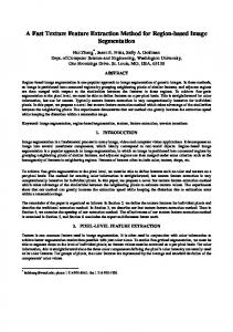
Fig. 1. CIS distortions caused by three movements of a CIS PC webcam: vertical lines in three CIS images are (a) slanted to the right, (b) stretched, or (c) bent due to their camera motions.
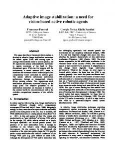
Fig. 1 shows examples of three CIS distortions in CIS images. The two images of Fig. 1(a) and (b) show the same bookshelf, but the CIS image in Fig. 1(a) shows a skew distortion due to the right directional motion of the camera. All the vertical lines in the image are slanted to the right. Fig. 1(b) looks stretched due to the upward motion of a camera. Also, Fig. 1(c) shows that the vertical lines are bent due to a rotational camera motion. The CIS distortions shown in those CIS images of Fig. 1 can also appear in a stabilized result, so the CIS distortion problem should be considered in the image stabilization process. Fig. 2 is an example of a CIS still image stabilization result without considering the CIS distortion. Fig. 2(a) shows a stabilized image with three thumbnail CIS images. Fig. 2(b) is the enlarged region of the dashed line region in Fig. 2(a) and shows that vertical lines of the image are slanted to the left due to camera motion. This is because CIS distortion was not considered in the image stabilization process. This paper proposes a fast CIS still image stabilization method which consists of two stages of image registration. The first stage is a global registration process and the second is a local registration process.
0098 3063/08/$20.00 © 2008 IEEE
198
Fig. 2. CIS distortion problem in CIS still image stabilization: (a) a stabilized result with three rapidly exposed CIS images, (b) the enlarged region of CIS distortion in the stabilized image (a).
The global registration removes CIS distortions while reducing the large displacement between CIS images by using an affine image transformation. Since the CIS distortion degrades the image quality, researchers have recently become interested in the CIS distortion of rolling shutter cameras [1]. Specifically, the CIS distortion is caused by a global image motion between two adjacent CIS frames, and several works developed methods using the global image motion to correct CIS distortions [2]-[6]. Our method uses the affine motionbased CIS distortion analysis [5]. Our local registration uses a mesh-based approach. The local registration reduces local misalignments like lens distortion or CIS distortion which cannot be exactly registered by using a parametric image transformation. Various image registration methods have been developed to carry out the local registration to reduce local misalignments within a small search range. These include dense image motion estimation [8], adaptive filtering [7], and 2D-mesh representation approach [9], [10]. The dense image motion estimation approach uses image gradients to compute optical flows at each pixel position. But, it tends to cause a high computational load and is fragile to errors in the motion field. The adaptive filtering framework, as in the 1-D case, takes the form of 2-D finite impulse response filter. But, this method depends on the scanning order of the entire image. Also, it is computationally expensive because its filter coefficients should be updated at each pixel position. The 2D-mesh representation approach tessellates an image area into triangular or quadratic meshes to estimate continuous local motions by using a block matching algorithm. The moving object and the parallax regions cannot be correctly aligned through two stages of our image registration. Those misaligned regions degrade the picture quality of a final stabilized result. To remove the misaligned regions due to the parallax regions or moving objects, we propose a two-stage post-processing method. This post-processing method is based on a labeling method considering the registration quality of neighborhoods and can make a clear stabilized image without those misaligned regions. To reduce the computational load in our method, we use a real-time global motion estimation method which is based on a fast block matching framework [5] in the global registration. The local registration then selectively carries out our mesh-based registration within highly misaligned local regions, not the entire image.
IEEE Transactions on Consumer Electronics, Vol. 54, No. 2, MAY 2008
This paper proposes a fast CIS image stabilization method using several CIS still images. Our method considers the CIS distortion and the parallax problem in the image registration process, and uses a fast local registration framework based on a real-time motion estimation method. This paper is organized as follows: Section II explains how to analyze CIS distortion during the global registration process. Section III presents our fast mesh-based local registration algorithm. Section IV shows how to make a final stabilized image without image artifacts such as parallax or moving object regions between registered images. Section V and Section VI present the experimental results of our CIS image stabilization method and the conclusions, respectively. II. CIS DISTORTION ANALYSIS IN GLOBAL REGISTRATION This section explains how to correct CIS distortion in CIS images during the global registration process.
Fig. 3. The global registration process and CIS distortion analysis.
Fig. 3 shows the overall framework of the global registration process in our CIS still image stabilization method. The input images to the global registration are several CIS images I cn starting from I c0 which are captured with short exposure times. All the affine global image transformations Tn between two adjacent CIS images I cn-1 and I cn are computed in real-time using a robust computation method [5]. This method uses a multi-resolution block matching algorithm with an efficient searching pattern, and also computes the motion parameters with a small number of reliable block features. Thus, the computational process is fast and robust to outliers such as positional uncertainties of block features and moving objects. The reference plane on which all CIS images are globally registered is chosen to be the plane defined by I1c in Fig. 3. I cn is globally registered onto I1c by computing a 3×3 global transformation G n between I1c and I cn in the following
W.-H. Cho and K.-S. Hong: A Fast CIS Still Image Stabilization Method without Parallax and Moving Object Problems
concatenation form:
Here, a1 , b1 , c1 , d1 , e1 , and f1
Gn =
in (4) are the motion
parameters of T1 which represent the relationship between
G 0 = T1 n +1
199
( Tk )
-1
(1)
n = 1, 2,L .
k =2
c n
Ø a1 Ø x1c ø Ø xc0 ø Œ = = T Œ œ œ Œ c1 1Œ º1ß º 1 ß Œ0 º
c 1
Using G n , I is globally registered onto I as follows:
Øxˆ cn ø Ø xnc ø = G n Œ Œ œ œ, º1ß º1ß
(2)
where x cn and xˆ cn are pixel positions of an original CIS image
I and its globally registered CIS image ˆIcn , respectively. c n
c 1
I is chosen as the reference image because it is the first image whose CIS distortion can be corrected by using T1 c 0
computed between two temporally adjacent CIS shots, I and
I1c , in Fig. 3 [5]. Thus, the first CIS frame Ic0 cannot be the reference image, so it is instead used to estimate T1 with I1c . After the global registration process, CIS distortions are removed from ˆIcn . Each ˆIcn has the same appearance as the reference image I1c because G n in (1) reflects the degree of CIS distortion between I1c and I cn . Thus, if I1c has a CIS distortion such as a skewing, shortening or stretching of vertical lines, ˆIcn also shows the same CIS distortion, which can be corrected by analyzing the CIS distortion in I1c . The CIS distortion in ˆIcn is removed by applying a CIS inverse distortion function D1-1 ( xc ) of I1c to ˆIcn as follows:
xˆ n = D1-1 ( xˆ cn ) ,
two CIS images I c0 and I1c as follows:
(3)
where xˆ n is the pixel position in ˆIn and ˆIn is the globally registered image without the CIS distortion. In (3), the CIS inverse distortion function D1-1 ( xc ) [5]
b1 d1 0
e1 ø c Øx ø f1 œœ Œ 0 œ , 1 1 œß º ß
(4)
where xc0 and x1c are pixel positions of Ic0 and I1c , respectively. Note that the global registration process computes only one CIS inverse distortion function D1-1 ( xc ) for the reference image I1c . III. A MESH-BASED LOCAL REGISTRATION The accuracy of global registration cannot always be sufficient to represent the global image motion between two CIS images. Depending on the camera motion, a different parametric motion model such as a Euclidean, affine, or projective transformation can be selected to define the global image motion. But, if there are locally varying image distortions such as lens distortions or CIS distortions due to non-uniform motions of the camera, another refining registration technique, a local registration, is required. The local registration is necessary for the still image stabilization because small misalignments in overlapping image regions can degrade the picture quality of the final image. Our local registration algorithm is based on a generalized block matching method [9]. Since the large displacements between the reference image and the other CIS images are already reduced by the global registration using a parametric transformation G n in (2), the local displacements within a smaller search range centered at a misaligned position can be found using a block matching algorithm. However, because the block matching algorithm cannot guarantee the motion continuity around the boundaries between blocks, we use the concept of a generalized block matching algorithm with regular rectangular meshes. Fig. 4(a) shows the result obtained by overlaying three globally registered images on a reference image. Fig. 4(b)
consists of the parameters in T1 as follows: K1d ( Hx c - e1 y c ) - b1 ( H - f1 ) ( y c ) -1 1
x=D
K1a K1d - b1c1 ( y c )
(x ) = c
2
(4)
2
,
K1a ( H - f1 ) y c - c1 ( Hx c - e1 y c ) y c Ł
K1a K1d - b1c1 ( y c )
2
ł
where K = H + ( a1 - 1) y and K = H + ( d1 - 1) y c , and H is a 1
c
d 1
the number of scan lines in the sensor.
Fig. 4. The global registration and its misaligned local image areas: (a) A global registration result, (b) The average image of intensity differences between the reference image and the other globally registered images.
200
IEEE Transactions on Consumer Electronics, Vol. 54, No. 2, MAY 2008
shows the image of average intensity differences between the reference image and three globally registered images. After the global registration in Fig. 3 is applied, there are some misaligned regions that appear largely around the edges in Fig. 4(b). The enlarged region in Fig. 4(a) shows that the character regions still appear blurred due to local misalignments. As shown in Fig. 4(b), the highly misaligned regions are not widely distributed over the entire image area but are confined to small local image areas. Thus, the local registration is not required at all pixel positions in the reference image. The computational load of the local registration process can be reduced by first finding the misaligned regions by measuring the root mean square (RMS) value of intensity differences between ˆI1 and ˆI n and carrying out the local registration only for image regions whose RMS values are above a threshold value.
where W i is the region covered by Pi1 in ˆI1 , and ˆI1 ( g) and
ˆI ( g) are intensity values at pixel position x in the reference n image and n-th image, respectively. If S (Pin ) is over a threshold value, it means that Pin is highly misaligned to Pi1 and the four corner points of Pin are selected as shown in Fig. 5(b). The local displacement of each control point in ˆI1 can be determined using a block matching algorithm (BMA). As shown in Fig. 5(d), the template size of the BMA centered at a control point is twice the block size of Pi1 so that its adjacent control points have similar local motions with that of the current control point. Since the four neighboring control points share half of the image information in their template, the displacement of the current control point is similar to the motions of its neighbors. In addition, the search range is restricted to the block size of Pi1 centered at a control point so that adjacent control points will not cross over each other. After all positions of the selected control points are locally registered by the BMA, a locally registered image of ˆI n is synthesized by backward mapping ˆI n onto ˆI1 .
Fig. 5. The mesh-based local registration: (a) A mesh domain in ˆI1 , (b) A selection of four control points on a mesh domain in ˆI n , (c) A difference image between ˆI1 and ˆI n , (d) The mesh-based block matching operation at a selected control point in ˆI n .
The overall procedure for our local registration is illustrated in Fig. 5. The algorithm begins by generating rectangular mesh domains on ˆI1 and ˆI n as shown in Fig. 5(a) and (b). A rectangular block Pin in ˆI n corresponds to block Pi1 in ˆI1 and has the four control points shown in Fig. 5(b). To avoid unnecessary operations in the local registration process, the control points are selected within highly misaligned regions. Those regions are determined using the quality of global
Fig. 6. Synthesizing a locally registered image with a bilinear transformation between two blocks in the reference mesh domain of ˆI1 and the locally registered mesh domain of ˆI n .
Fig. 6 shows the two mesh domains of ˆI1 and ˆI n . After our mesh-based local registration algorithm is applied to the mesh domain of ˆI n , its control points are locally registered to ˆI1 . Since the locally registered mesh domain of ˆI n cannot be
registration between ˆI1 and ˆI n which is measured using
represented by a parametric projection transformation, we use a bilinear transformation for each block image area [9], [10]. The bilinear transformation warps each locally registered
intensity differences between the two images. As shown in Fig. 5(c), the RMS value of the intensity differences within each Pin , or S (Pin ) , is computed as [7], [9]
shown in Fig. 6. After applying the bilinear transformation to all blocks in ˆI n , the locally registered image is added onto the
S ( Pi n ) =
1 Wi
( ˆI (x) - ˆI (x) ) , 2
x˛W i
n
1
(5)
block Pin in ˆI n onto its corresponding block Pi1 in ˆI1 as
reference image to make a final image.
W.-H. Cho and K.-S. Hong: A Fast CIS Still Image Stabilization Method without Parallax and Moving Object Problems
IV. THE PARALLAX AND MOVING OBJECT PROBLEMS IN IMAGE REGISTRATION When a final stabilized image is made, all image blocks of CIS images should be exactly aligned to the corresponding reference image blocks. But, when CIS images are continuously captured, some images can include regions which are not visible in the reference image. This troublesome case can occur when the viewpoint of the camera is slightly changed due to shaking motions. The block regions which contain the parallax or moving object regions cannot be locally registered to the reference image. Thus, those regions look blurred, degrading the picture quality of the stabilized image.
201
neighboring blocks. This causes some block artifacts in the final result, as indicated by the white arrow in Fig. 7(c). The indicated regions are neighbors of misaligned regions, but they were still not removed by the single-threshold method because their S (Pin ) was lower than vth . The parallax regions are usually confined to small areas, as shown in Fig. 7(b). The single-threshold method cannot remove all the blocks in those regions because S (Pin ) in some of the blocks is lower than vth . Setting the threshold value lower can help remove more misaligned blocks, but it is still problematic. Thus, the misaligned blocks are removed from locally registered images using the following two-stage post-processing method before a stabilized image is synthesized. The first stage removes the misaligned blocks due to the parallax or moving object regions, and the second stage removes small sub-regions which cannot be detected by the first stage. A. The removal of misaligned blocks using labeling method The first stage in our two-stage post-processing method removes misaligned blocks and their undesirable neighbors together based on a labeling method. Our mesh-based local registration gives two mesh domains, the reference mesh domain of ˆI1 and a locally registered mesh domain of ˆI n .
Fig. 7. The parallax region problem in a CIS still image stabilization result: (a) A result image with four rapidly exposed CIS images, (b) A result without removing the parallax regions, (c) A result with the singlethreshold method.
Fig. 7 shows how the parallax regions can degrade the quality of a final result. The thumbnail images I c0 ∼ Ic3 of Fig. 7(a) were captured when a camera was slightly shaking with a fixed viewpoint on a cylindrical object. Due to this camera motion, there are some invisible regions around the object in the reference image that became visible in the other images. As a result, those regions around the cylindrical object are misaligned, as shown in the final result of Fig. 7(b). The misaligned blocks can be removed from each locally registered image so that they will not be overlaid onto the reference image by first computing S (Pin ) of block Pin using (5) and then testing whether S (Pin ) is over a predefined threshold value vth or not. If the value is below vth , we add
Pin onto its corresponding Pi1 in ˆI1 . If not, we preserve Pi1 n i
without adding the misaligned block P . Fig. 7(c) shows a stabilized result after this single-threshold process is applied to the result of Fig. 7(b). The stabilized image in Fig. 7(c) was made by applying the single-threshold method to all the locally registered images to remove misaligned blocks from each image. Then, all the remaining blocks are overlaid onto the reference image. The single-threshold method removes only the blocks whose S (Pin ) are above vth , and it does not consider the
Like the single-threshold method, this stage tests whether the quality of local registration within Pin is good enough to be overlaid onto Pi1 using (5). Each Pi1 is assigned a label ci and two operations are defined depending on the label of ci . If
ci = 0 , the two blocks Pi1 and Pin are overlaid, and if ci = 1 , Pin is not overlaid onto Pi1 . Then, the problem can be converted to finding the binary configuration c for all labels ci . The neighborhood relationship is incorporated into this problem by formulating the energy function E ( c ) as follows: E (c) = i˛G1
Ł
V1 (ci ) +
j˛¥ i ,i „ j
(10)
V2 (ci , c j ) , ł
where G is the set of all blocks in the reference mesh domain 1
of ˆI1 and ¥
i
is a set of four neighborhood blocks.
Our solution is c ˛ £ which minimizes E ( c ) , that is, *
c* = min غ E ( c ) øß where £ c˛£
is the set of all the binary
(
configurations. In (10), V1 ( ci ) and V2 ci , c j follows:
)
are defined as
202
IEEE Transactions on Consumer Electronics, Vol. 54, No. 2, MAY 2008
(11)
artifacts in the final stabilized image. Thus, the small misaligned sub-regions around the blocks removed through the first stage can be found as illustrated in Fig. 8. After the binary labeling process of (10) is finished, the label of a block Pi1 has ci = 1 or 0. The binary image in Fig.
where S (Pin ) is the RMS of intensity differences in Pin
8(a) is a mask image where the blocks with ci = 1 are white
computed using (5).
and the blocks with ci = 0 are black. The enlarged region of
S ( Pi n ) if ci = 0
V1 ( ci ) =
v1
if ci = 1
V2 ( ci , c j ) =
v2 if ci „ c j 0 if ci = c j
,
V1 ( ci ) in (11) acts as a single-threshold constraint. If
S (Pin ) is over v1 , E ( c ) in (10) gets bigger than the energy in the case of ci = 1 , so ci is changed to 1 to minimize E ( c ) .
(
Also, V2 ci , c j
) in (11) makes the label of c
i
consistent with
its neighbors c j , the four neighboring blocks. If the label of
ci is not consistent with its neighbors, its inconsistency makes E ( c ) increase, so the label of ci is changed.
the mask image in Fig. 8(a) shows that the white mask blocks are surrounded by boundary blocks. The boundary block is the block Pi1 which has its label ci = 0 and has one or more white mask block among its four neighboring blocks. These boundary block are searched for misaligned sub-regions which are indicated by misaligned sub-blocks in Fig. 8(a) and (b). The misaligned sub-blocks can be found within the boundary block by using a 3×3 sliding window, as in Fig. 8(b). At each pixel position in a boundary block, an average value of intensity differences is calculated between the reference image
ˆI and the locally registered image ˆI within the 3×3 sliding 1 n
The solution c* ˛ £ can be obtained in the following iterative manner. Set all labels of ci to 0 in the initial stage.
window. If the average value is over a threshold value vth , the
Then, at each ci , compute E(c) by changing the label of ci
block. These sub-blocks are not overlaid onto ˆI1 .
to 0 or 1 in order to check whether E ( c ) decreases or not. If
E ( c ) decreases when ci is changed, the change is kept. If not, the label of ci is preserved. Then, the next ci is visited. After all ci are visited, the number of changed labels is counted and the next iteration begins unless there are labels of ci changed. This iterative procedure takes several iterations and converges to the final solution c* .
3×3 window region at that position is set as a misaligned sub-
V. EXPERIMENTAL RESULTS This section shows our CIS image stabilization results using a set of continuously captured CIS images. Images were captured by a PC USB CIS web camera which uses a 330Kpixel color CMOS image sensor with a video resolution of 640×480 at 15 frames per second (fps). The test images of our CIS still image stabilization were obtained by recording a short-length CIS video with slight shaking motions and then sequentially extracting three or four frames from it.
B. The removal of misaligned sub-blocks
Fig. 8. The removal of misaligned sub-blocks: (a) The mask image obtained by the binary labeling problem, (b) The sub-block removal process.
The second stage following the removal of misaligned blocks removes misaligned sub-regions around misaligned blocks removed by the first stage to avoid block artifacts in the stabilized image. If some of the blocks subdivide misaligned regions into small sub-regions due to the size of mesh blocks, they will not be detected as misaligned through the first stage due to their low values of S (Pin ) . This can make block
Fig. 9. CIS distortion problem in a CIS still image stabilization result: CIS still image stabilization results (a) without and (b) with our CIS distortion analysis.
Fig. 9 shows the CIS distortion problem in a CIS still image stabilization result. To show the importance of our CIS distortion analysis in CIS still image stabilization, three CIS
W.-H. Cho and K.-S. Hong: A Fast CIS Still Image Stabilization Method without Parallax and Moving Object Problems
images were captured with a fast horizontal motion to make skew distortion. Fig. 9(a) is an image without considering CIS distortion and Fig. 9(b) is an image with a CIS distortion correction in the image registration process. As seen in the two dashed bounding boxes in Fig. 9, a CIS skew distortion is removed in the image registration process.
Fig. 10. CIS still image stabilization: (a) Four CIS images with short exposure times, (b) A simple overlaying result without any image registration, (c) Our global registration result, (d) Our mesh-based local registration result.
Fig. 10 shows the result of applying our CIS still image stabilization method to four CIS still images. Fig. 10(a) shows the four thumbnail images with an exposure time five times shorter than the auto exposure time. Fig. 10(b) is the result of simply overlaying the four images from Fig. 10(a) without any image registration. Since the CIS camera was shaking while focused on a cylindrical object, Fig. 10(b) shows that the foreground motion of the cylindrical object is different from the background motion around it. Thus, as shown in the global registration result of Fig. 10(c), the cylindrical object is poorly registered compared to its background after the global registration because the accuracy of global registration is insufficient. To reduce local misalignments, we applied the mesh-based local registration with an 11×11 mesh block, 21×21 template window, and 9×9 search window. Fig. 10(d) shows that locally varying distortions were removed after the mesh-based local registration was applied. Here, the performance of the mesh-based local registration was evaluated using the PSNR value [7], [11], which is defined as PSNR = 10 log10
255 2 1 W ·H
x
( ˆI ( x ) - ˆI 1
n
( x))
2
,
(13)
where W×H denotes the image size, and ˆI1 ( g) and ˆI n ( g) are intensity values at pixel position x in the reference image and n-th image, respectively.
203
The PSNR value is calculated between the reference image ˆI and locally registered image ˆI . The average PSNR values 1 n for the final stabilized results are 35.9 dB and 39.9 dB for Fig. 10(c) and (d), respectively. Fig. 11 shows final stabilized results with and without our two-stage post-processing method. Fig. 11(a)-(c) show the same region in a stabilized image and Fig. 11(A)-(C) are enlarged images of the boxes indicated in Fig. 11(a)-(c), respectively. Fig. 11(a) is the result without removing misaligned blocks. Since the parallax regions around the cylindrical object cannot be correctly aligned in the image registration process, Fig. 11(A) shows that those regions look blurred. Fig. 11(b) is the result with a single-threshold method and the blurred regions in Fig. 11(A) are removed in Fig. 11(B). But, Fig. 11(B) still has block artifacts indicated by the white arrow, which is the problem of the single-threshold method. Fig. 11(c) is the result with our two-stage postprocessing method, which removes misaligned blocks and some sub-blocks around the misaligned ones. As shown in Fig. 11(C), the block artifacts observed in Fig. 11(B) are removed because our method considers the registration qualities of neighborhood blocks in the block removal process. For this experiment, the single-threshold method used vth = 14 . Our two-stage post-processing method used v1 = 10 and v2 = 5 for
V1 ( ci ) and V2 ( ci , c j ) in (11), and vth = 10 for the removal of
misaligned sub-blocks in Fig. 8.
Fig. 12. The moving object problem in the CIS still image stabilization: (a) Four CIS images with short exposure times, (b) Our global registration result, (c) Our CIS still image stabilization result without two-stage post-processing method, (d) Our CIS still image stabilization result with two-stage post-processing method.
Fig. 12 shows the moving object problem in CIS still image stabilization. Fig. 12(a) shows four CIS images with an
204
IEEE Transactions on Consumer Electronics, Vol. 54, No. 2, MAY 2008
Fig. 11. Removing misaligned regions: (a),(A) No post-processing, (b),(B) A single-threshold method, (c),(C) Our two-stage post-processing method.
exposure time three times shorter than the auto exposure time. In Fig. 12(a), a person is leaning back in a chair. The global registration result in Fig. 12(b) shows that the regions of the person are poorly registered compared to the background. This is because the foreground motion is different from the background motion. Fig. 12(c) is the image stabilization result without our two-stage post-processing method. In Fig. 12(c), there are the misaligned regions around his head and shoulder. Those regions cannot be correctly registered because their regions are changed due to the movement of the upper body. Our final stabilized result with our two-stage post-processing method in Fig. 12(d) shows that our method effectively removes the misaligned regions. This experiment used the same parameters as Fig. 10 and Fig. 11 for our local registration and post-processing. The average PSNR values are 28.7 dB, 33.9 dB, and 39.2 dB for Fig. 12(b), (c), and (d), respectively.
Fig. 13. The proposed CIS still image stabilization result with our twostage post-processing method.
Our CIS still image stabilization method can be used as a fast stabilization algorithm in CIS cameras. Fig. 13 is the final stabilized image with four 640×480 CIS images. As shown in Fig. 11, those images have the parallax problem. In the global registration in Fig. 3, we estimate the affine global image motion Tn with the frame rate of 45 fps by using our fast and robust block matching algorithm [5]. The frame rate of the global registration is 9.0 fps because the image warping algorithm including the global image warping and
CIS distortion correction process is not fully optimized. Our mesh-based local registration runs at the frame rate of 27.2 fps including the processing time of our two-stage postprocessing method. The mesh-based local registration has parameters of an 11×11 mesh size, 21×21 template window, and 9×9 search range. Thus, the overall frame rate of our CIS still image stabilization is 6.8 fps using a Pentium IV CPU 2.6GHz for the stabilization image as shown in Fig. 13. Since the still image stabilization usually uses 3 or 4 frames depending on digital camera systems, we expect that our CIS still image stabilization method can be adopted as a practical still image stabilization solution in CIS cameras if the image warping algorithm is improved.
VI. CONCLUSION This paper presented a fast CIS still image stabilization method using several rapidly exposed CIS images. To eliminate CIS distortions in the CIS images, a global registration framework was proposed that was capable of correcting CIS distortions in the image registration process. Local misalignments in the image registration were removed by a fast local registration algorithm which was applied to highly misaligned local regions in the image. Also, to remove the parallax or moving object regions that could not be correctly aligned to a reference image were removed by a two-stage post-processing method. Since our post-processing method could detect and remove misaligned blocks in locally registered images, it could make a final stabilized image without block artifacts. Our CIS still image stabilization method can be used as a practical still image stabilization technique in CIS cameras that can handle CIS distortion problems as well as the parallax or moving object problem. Real-time application is possible if the image warping algorithm is fully optimized in our global registration process.
W.-H. Cho and K.-S. Hong: A Fast CIS Still Image Stabilization Method without Parallax and Moving Object Problems
REFERENCES [1]
Christopher Geyer, Marci Meingast, and Shankar Sastry, “Geometric models of rolling-shutter cameras,” IEEE Workshop on Omnidirectional Vision 2005. [2] J. H. Hwang, “CMOS image sensor distortion compensation method,” Korea Patent 10-0092224, 2003. [3] C.-K. Liang and H. H. Chen, “Rolling shutter distortion correction,” SPIE Proc. Visual Communication and Image Processing, Beijing, China, Jul. 2005. [4] Jeong-A Im, Dae-Woong Kim, and Ki-Sang Hong, “Digital video stabilization algorithm for CMOS image sensor,” IEEE Proc. Int’l Conf. on Image Processing, Oct. 2006. [5] Won-ho Cho and Ki-Sang Hong, “ Affine motion based CMOS distortion analysis and CMOS digital image stabilization, ” IEEE Trans. on Consumer Electronics, vol 53, no. 3, pp.833-841, Aug. 2007. [6] Won-ho Cho, Dae-Woong Kim, and Ki-Sang Hong, “ CMOS digital image stabilization,” IEEE Trans. on Consumer Electronics, vol. 53, no. 3, pp.979-986, Aug. 2007. [7] Gulcin Caner, A. Murat Tekalp, Gaurav Sharma, and Wendi Heinzelman, “Local image registration by adaptive filtering,” IEEE Trans. Image Processing, vol. 15, no. 10, pp.3053-3065, Oct. 2006. [8] H. Liu, R. Chellappa, and A. Rosenfeld, “Accurate dense optical flow estimation using adaptive structure tensors and a parametric model,” IEEE Trans. Image Processing, vol. 12, no. 10, pp.1170-1180, Oct., 2003. [9] Chung-Lin Huang and Chao-Yuen Hsu, “A new motion compensation method for image sequence coding using hierarchical grid interpolation,” IEEE Trans. Circuits and Systems for Video Technology, vol. 4, no. 1, pp.42-52, Feb., 1994. [10] Yuichiro Nakaya and Hiroshi Harashima, “Motion compensation based on spatial transformations,” IEEE Trans. On Circuits and Systems for Video Technology, vol. 4, no. 3, pp.339-367, June, 1994. [11] Jae Hun Lee, Kyoung Won Lim, Byung Cheol Song, and Jong Beom Ra, “A fast multi-resolution block matching algorithm and its LSI architecture for low bit-rate video coding,” IEEE Trans. Circuits and Systems for Video Technology, vol. 11, no. 12, pp.1289–1300, Dec. 2001.
205
Won-Ho Cho received the B.S. degree from Electronic and Electrical Engineering, KAIST, S. Korea in 1996 and received the M.S. degree from Electronic and Electrical Engineering, POSTECH, S. Korea in 2001. In 1998, he worked as a visiting researcher in ETRI, S. Korea and he is currently a PH.D candidate in Electronic and Electrical Engineering in POSTECH, S. Korea. His research interests include multi-object tracking, high dynamic range imaging, contour based segmentation, and video enhancement. Ki-Sang Hong received the B.S. degree in Electronic Engineering from Seoul National University, S. Korea in 1977, the M.S. degree in Electrical and Electronic Engineering in 1979, and the PhD degree in 1984 from KAIST, S. Korea. From 1984 to 1986 he was a researcher with Korea Atomic Energy Research Institute and in 1986 he joined POSTECH, Korea, where he is currently a professor with the Division of Electrical and Computer Engineering. From 1988 to 1989 he was a visiting professor with Robotics Institute at Carnegie Mellon University, Pittsburgh, Pennsylvania. His current research interests include computer vision, augmented reality, pattern recognition, and color image processing.