Aug 21, 1998 - The bu er's logic consists of a standard self-timed FIFO (e.g. ... Keywords asynchronous communication mechanisms, FIFO bu er, four-slot ...
A FIFO bu�er with real-time interface� A. Yakovlev
D.J. Kinniment F. Xia Department of Computing Science Department of Electronic Engineering University of Newcastle upon Tyne NE1 7RU England August 21, 1998 Abstract
The design of a FIFO bu�er with fully asynchronous, non-blocking write and read operation is presented. The bu�er's logic consists of a standard self-timed FIFO (e.g. pipeline) surrounded by two special interface blocks, In and Out, connected to Writer and Reader, respectively. To avoid temporal blocking of Writer requesting for a write when the pipeline is full the In block implements skipping of the data item. Similarly, if Reader attempts to read an empty pipe, to avoid its blocking, a special acknowledge signal is produced telling Reader to re-read the previous item. These blocks are synthesised from their Signal Transition Graph (STG) speci cations using an asynchronous circuit synthesis tool, petrify. The proposed solution is compared and contrasted against a previously known four-slot mechanism.
Keywords asynchronous communication mechanisms, FIFO bu�er, four-slot algorithm, real-time systems, self-timed circuits
1 Introduction Parallel distributed real-time systems require reliable means for data transfer between their data-processing subsystems. Regardless of the level of abstraction, and whether considered either as software or hardware, it is becoming increasingly di�cult to synchronise such subsystems, which are often driven by their own clocks and/or timing constraints [1]. At the higher level, in systems of concurrent real-time processes, the use of request-acknowledgement and mutual exclusion methods may be unacceptable due to their \temporal-blocking nature", where e.g. a process `Writer' is temporarily (and maybe for an unpredictable period) blocked from putting the new data into a channel until a process `Reader' has nished removing previous data. At the lower level, in modern VLSI chips, the constant reduction in feature size leads to the increase of interconnection delays relative to gate delays. This causes signi cant clock skew and thereby prevents synchronisation by means of global clocking [2]. �
Work is supported by EPSRC (project COMFORT, GR/L93775).
1
The use of self-timed handshake protocols instead of a global clock may again be undesirable because of their impact upon real-time performance. Thus, a form of communication is required, which allows real-time requirements and technological advances to be sustained. This leads to the adoption of inherently asynchronous communication.
2 Asynchronous communications Asynchronism is understood here as the property of the system in which processes may not a�ect the timing of each other as a direct result of their communication for data passing [4]. Depending on the extent of asynchronism in systems, the types of communication protocols used in parallel systems can be subdivided into three main classes: (1) fully synchronous; (2) partially asynchronous or loosely synchronous, and (3) fully asynchronous. The ReaderWriter paradigm will be used here for illustration. \Fully synchronous", as was shown above, is the most rigid form of temporal dependence of processes upon one another. It may be required for transferring extremely urgent pieces of data, when both Writer and Reader must synchronise on the transmission action before they can progress further. This is achieved by a bu�er with only one shared memory location. \Partially asynchronous" still preserves some degree of temporal dependence by using a bounded bu�er. Its purpose is to support message passing with inevitable timing interference when Reader is held on empty bu�er, or Writer is held when the bu�er is full. This is typically achieved by a nite FIFO bu�er. \Fully asynchronous" communication is the least commonly considered branch of this taxonomy. destructive writing and non destructive reading. It leads to a reference data mechanism in which no temporal dependence between the reading and writing processes is possible [4]. The price for such temporal decoupling, is however that Reader may read the same data more than once (Reader faster than Writer), and Writer may lose the data which has not yet been read by overwriting it with new data (Writer faster than Reader). Depending upon the application, this may or may not matter. More serious, however, is the possibility that the communication protocol might lead to a sequencing error - e.g. the reading of an old item of data after a newer item has been read, or that a byproduct of a concurrent read/write could be data corruption. The advantages of not having to synchronise Reader and Writer include reliability (if one of the processes gets stuck at some point it cannot a�ect the other process), increased throughput (all parts of the system process data at their own speed, without waiting for each other) and reduced resource requirements (no need to `build' unbounded bu�ers). The use of fully asynchronous communication in designs of systems for safety-critical and real-time applications, where individual subsystems must coexist within a set of timing \ rewalls"[1], is a critical issue in system dependability [8].
3 Existing solutions for fully asynchronous communications Simpson's four-slot mechanism [4] has shown that with four shared memory locations it is possible to provide fully asynchronous communication. Recent research has highlighted the importance of two properties of asynchronous communication, data coherence and data freshness . The former implies that both Writer and Reader never access the same data 2
slot simultaneously; the latter implies that Reader, having already read data written at some instance of time never reads older data. Two known algorithms support both these properties, but the algorithms have been shown to partially fail under certain operating abnormalities (metastability [3], etc.). Furthermore, the solution for a non-blocking communication proposed in the four-slot mechanism is not intuitively obvious with respect to its two main properties. It does not immediately guarantee correct sequencing since there is no clear imposition of the FIFO order on the data travelling between its reading and writing sides. On the other hand, if the use of a FIFO discipline had been combined with the advantages of the non-blocking interaction of the data bu�er with Writer and Reader, similar to that of the four-slot mechanism, this would have produced a system with a predictable (and apparently controllable through the size of the FIFO) and intuitively clear (due to FIFO order) notion of sequencing.
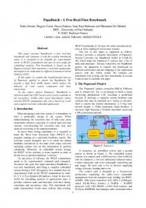
4 A FIFO bu�er with non-blocking interface Although the classical FIFO bu�er helps to average out the (temporary) di�erences in the rate between writing and reading data, it is still a blocking mechanism. If the average speeds of Writer and Reader di�er the bu�er will start blocking the activity of the faster party. In this work we are motivated by the real-time requirements and would therefore like to design a FIFO bu�er with non-blocking Writer and Reader interfaces. The property of nonblocking is achieved through the use of the following policy. If Writer attempts to add a new data item to the bu�er when the latter is full, the data will be `skipped'. The skipped data, if tagged appropriately, may in principle be collected for future use but this functionality comes outside the scope of this bu�er. Similarly, on the reading side, if the bu�er is empty while Reader attempts to read, the bu�er will send a special acknowledgement to Reader indicating that the latter can use the previously read data. Thus, when writing the full pipe the data-skipping method is used and in case of reading the empty pipe re-reading is applied. Another possiblity for the full-writing case would have been overwriting the previous data in one of the stages (say, the last one). A problem of data coherence may however arise here. Indeed, unless the entire pipe is locked 1 when one of its stages is being overwritten, there is always a risk of corruption in the data path if the overwriting of the previous data in a pipeline stage is allowed at the time when the previous value is being copied into the next stage. We have prefered here to use a simpler mechanism, that of skipping data on the writing side. The structural view of such a bu�er is shown in Figure 1 (top of the gure). Its re nement in terms of two interfaces, In and Out, and an ordinary self-timed FIFO is shown at the bottom. The real-time bu�er has a fairly standard handshake interface with the Writer and Reader units. The use of handshakes is here purely for convenience and does not imply blocking synchronisation. The following conditions are assumed to support this idea.
Real-Time (RT) conditions:
(1) The delay between the WrReq event and WrAck event must be bounded, independent of the delays involved in Reader and determined only by the \local" parameters of the circuit, such as the critical cycle of the operation of the In interface 2 and perhaps the propagation The problem of locking the entire pipe, which is normally `resilient' in its operation, is also non-trivial though can in principle be resolved by means of arbitration. 2Strictly speaking, if the In block uses a self-timed arbiter inside, such a delay may theoretically be 1
3
WrData Writer
WrReq WrAck
WrData
RdData
Real-Time FIFO
InData
WrReq
InReq InAck
WrAck In
Self-Timed FIFO
SkpData SkpReq
RdReq RdAck RdOld
Reader
OutData
RdData
OutReq
RdReq
OutAck Out
RdAck RdOld
Skip
Possible use
Figure 1: Structural view of real-time FIFO and its re nement with In and Out interfaces. delay of the rst stage of the self-timed pipeline when that stage is initially ready to receive the new data (i.e. empty). (2) The delay between the RdReq event and RdAck (or RdOld) event must be bounded, independent of the delays involved in Writer and determined only by the \local" parameters of the circuit, such as the critical cycle of the operation of the Out interface 3 and perhaps the propagation delay of the last stage of the self-timed pipeline when that stage is initially ready to send the new data (i.e. full). The operation of the interface blocks, In and Out, can be de ned using handshake signalling protocols. Two such protocols are commonly used [13]: � the two-phase or non-return-to-zero (NRZ) protocol, which is de ned on signal transitions regardless of their direction (the rising edge of a signal is semantically equivalent to the falling edge); � the four-phase or return-to-zero (RZ) protocol, which requires both signals in the handshake to return to their original (normally logical 0) state. In this paper, we will use Petri nets and Signal Transition Graphs (STGs) to describe the behaviour of the In and Out interfaces. Petri nets are widely accepted as a formal language for the speci cation and analysis of discrete event systems, including digital circuits [9, 10]. STGs are a speci c interpretation of Petri nets, in which events are associated with rising and falling signal transitions. STGs are therefore a formal way of specifying with timing diagrams. With the availability of software tools like petrify [11], STGs are becoming increasingly common for the synthesis of asynchronous circuits. The Petri net (or STG) description of the operation of the In and Out interfaces for the NRZ protocol are shown in Figure 2 (a) and (b), respectively. These STGs are event-based, unbounded due to metastability, but in practice, metastability is resolved within a fairly predictable interval. In any case, metastability resolution time for a bistable must be taken into account in any solution with real-time conditions. 3Analogous argument can be applied concerning the metastabilty that may potentially occur in the Out block.
4
WrReq~
Full tag1
SkpReq~
RdReq~
Empty
InAck~
InReq~
tag+
Empty tag0
tag0
RdOld~
tag-
Full tag1
OutReq~
OutAck~
tag-
tag+
RdAck~ WrAck~ (a)
(b)
Figure 2: STG models (two-phase models) of the In and Out interfaces. hence most signal transitions in them are of a `toggle' type. They are labeled with tilde (�). The only level-based signal is \tag", whose rising and falling edges are semantically di�erent. The value of tag equal to 0 (1) stands for the situation when the rst stage of the self-timed FIFO is Empty (Full). The meaning of the STG model in Figure 2 (a), for example, is following. Let the rst stage be initially empty (a token is in place tag0). Assume Writer sends a write request by issuing a (rising) signal transition on WrReq (the Petri net transition labelled with WrReq� res). It is then clear that the next enabled transition will be InReq�. After its ring both tag+ and InAck� are enabled and system enters concurrent operation. After tag+ res, a signal transition on WrAck is generated, followed by possibly a new request (WrReq�) from Writer. At the same time, the rst stage of the pipe may copy the data into its data path register, and re the InAck� transition, followed by the reset of the tag back to zero. However, if the pipe becomes full, e.g., due to slow acting of the reading side, it may take a long time before the InAck� event occurs. In that latter situation, when the new WrReq� res, the tag may still be in its high state, and another branch of the In interface will be activated, namely the SkpReq� transition. Similarly, one could trace the operation of the STG of the Out unit in Figure 2 (b). The direct circuit implementation of the STGs in Figure 2 would however be hazardous. Indeed, there is no mechanism protecting the transitions of SkpReq and InReq when tag goes from 1 to 0. In order to let the state of the tag signal to stabilise when SkpReq and InReq are enabled, we can apply a semaphore method. The latter is typically employed in concurrent software systems, to protect certain critical resources (where data coherence may be at risk). The semaphore (also known as a mutual exclusion or mutex) actions are inserted into the STG speci cation using the method described in [12]. The semaphore variable is modelled in Petri nets by a place with a single token. The token is arbitrated (and consumed) between transitions that stand for the wait operations on the semaphore. The token is returned back to that place by the transitions that correspond to the signal operations. The STG description of the operation of the In interface with semaphore actions, wait(me) and signal(me), to protect the critical section from metastable behaviour and potential hazards is shown in Figure 3. In this two-phase model, the role of the semaphore (mutex) 5
WrReq~
InAck~ mutex (me)
r1~
r2~
g1~ wait(me)
SkpReq~
Full tag1
Empty tag0
g2~ wait(me)
InReq~
tag-
tag+
WrAck~ d2~ signal(me)
d1~ signal(me)
Figure 3: Two-phase STG model of the In block with mutex critical section protection based on RGD arbiter. implementation is played by a Request-Grant-Done (RGD) arbiter [13]. Similar description but for a four-phase (RTZ) protocol is shown in Figure 4, where the semaphore is implemented through a standard 2-input 2-output mutex element [14]. Note that in this model the role of tag is implicit; it is played by signal InReq. The circuit implementation obtained by means of a fairly trivial syntactic transformation of a Petri net to a two-phase control logic (described e.g. in [10]) is shown in Figure 5. This circuit contains besides an RGD arbiter also two standard two-phase components, a Selector (sel) and a Variable (var) with acknowledged set and reset. The implementations for sel and var are shown in Figure 6 (a) and (b), respectively. The circuit implementation obtained with tool petrify [11] is shown in Figure 7. It should be noted that in the process of synthesis, to resolve a complete state coding problem [11], the tool has inserted an additional state signal named \csc". The four-phase STG for the Out interface and its circuit implementation (via petrify are shown in Figures 8 and 9, respectively. Again, instead of adding a separate signal, OutAck can be used for empty/full tagging. As noted above, to satisfy the basic real-time conditions, the interaction between the control logic in the In and Out interfaces and the control logic of the self-time FIFO must be organised in appropriate way. Namely, we would like to keep the domain of signals that determine the worst case path of response to Writer and Reader `local' to the In and Out circuits. This interaction should also allow a feasible way of interfacing with the data path, so that one of the standard types of latches, transparent or edge-triggered, could be used to store data. One possible way of interconnection between the control logic and the data path in the new bu�er is schematicaly shown in Figure 10. Here, we presume that the data path latches are edge-triggered. 6
WrReq+
InAck+ mutex (me)
r1+
r2+
g1+ wait(me)
SkpReq+
Full tag1
Empty tag0
g2+ wait(me)
InReq-
InReq+
WrAck+ InAckWrReqSkpReq-
dummy
r1signal(me)
r2-
g2-
g1-
signal(me)
WrAck-
Figure 4: Four-phase STG model of the In block with mutex critical section protection based on a two-way mutex element.
WrReq
InAck
(0) (0) (0)
r1
r2
g1
RGD g2 arb
d1
d2
(0) (0) (0) tag
(0) (0)
BoolIn Out0
RstAck
RstReq
BoolOut
var
SetAck
SetReq InReq (0)
In sel
SkpReq
Out1 (0) WrAck (0)
Figure 5: Two-phase circuit implementation of the In interface.
7
boolIn
Out0
SetReq
TL
TL
SetAck
In
Out1
RstReq
TL
TL
RstAck
boolOut
(b)
(a)
Figure 6: Circuit implementations of Select (a) and Variable (b).
InAck
WrReq
r1
(0)
r2
g1
g2
(0)
(0)
(0)
mutex (0)
InReq (0)
csc (0)
(0)
WrAck (0)
SkpReq (0)
(0)
Reset (1)
Figure 7: Four-phase circuit implementation of the In interface.
8
RdReq+
OutReq+ mutex (me)
r1+
r2+
g1+
Empty tag0
RdOld+
RdAck+
RdReq-
RdReq-
r1-
r1-
g1-
g1-
RdOld-
RdAck-
Full tag1
g2+
OutAck+
OutReq-
OutAck-
r2-
g2-
Figure 8: Four-phase STG model of the Out block with mutex critical section protection based on a two-way mutex element.
OutReq
r2
(0) (0)
mutex g2
RdReq
r1 g1
(0) (0) OutAck csc
(0)
(0) Reset (1)
RdAck (0)
RdOld (0)
Figure 9: Four-phase circuit implementation of the Out interface
9
WrData
Data Latches
WrReq
WrAck
InReq IN
InData
OutData
Data Latches
Data Latches
OutReq C
RdAck
C OutAck
InAck
RdData
OUT
SkpReq
RdReq RdOld
One Stage of Self-Timed Pipeline Control
Figure 10: Interconnection with data path Let us now estimate the worst case signal transition paths for Writer and Reader: �
�
The worst case for Writer corresponds to the situation when the WrReg+ transition occurs concurrently with the arrival of InAck+ from the rst stage of the pipe (after the previous data has been sent there with InReq+); the InAck+ must then win the mutex. The critical sequence of events (cf. Figure 4) will be as follows: WrReq+, InAck+, r1+, r2+, g2+, Inreq-, InAck-, r2-, g2-, g1+, InReq+, WrAck+, WrReq-, r1-, g1-, dummy, WrAck-. The actual delay of this path can be easily estimated from the parameters of the circuit implementation. Let us shown that it is independent of the Reader's delay 4. It is clear that although the circuit involves arbitration element, it is not possible for the \pipe side" to request (and hence win) arbitration more than once without having executed at least one cycle of the WrReq, WrAck handshake. Thus, Writer's process can only be \delayed" by maximum one pipeline handshake halfcycle, between Inreq- and InAck-. This period occurs in a predictable time because, as can be seen from the implementation of a self-time pipeline stage (Figure 10), the resetting phase of the stage does not depend on the state of the subsequent stage (it is a su�ciently decoupled control); it is virtually the delay of a C-element. The only (\theoretically") remaining unknown factor in the above path is the delay of the potential metastability due to arbitration between the rising requests, r1+ and r2+. In practice, this bound can be estimated conservatively with extremely high probability [15]. The worst case for Reader is associated with the following sequence of events, tracable in Figure 8: RdReq+, OutReq+, r1+, r2+, g2+, OutAck+, OutReq-, r2-, g2-, g1+, RdAck+, RdReq-, OutAck-, r1-, g1-, RdAck-. The actual delay is again determined by the delays of the circuit implementation. Here, again the pipeline's side can only win arbitration once, and the period involved is between the OutAck+ and OutReq-, which is the resetting phase of the handshake (again, the delay of a a C-element) and hence independent of the state of the previous stages
In fact a weaker statement is shown here, that it depends only on the logic delay of the rst stage of the self-timed pipe. 4
10
The above analysis has shown that the design satis es the real-time conditions outlined in the beginning of this section. The \write skip" and \read old" paths can be easily traced in the same STGs and they also meet the real-time conditions.
5 Comparison with the four-slot method The proposed method of asynchronous communication and its circuit implementation presents the following advantages over the four-slot mechanism described in [4]: � � � �
simplicity, both in its actual description and its intuitive correctness; it guarantees sequencing by de nition (use of FIFO); it reduces miss (skipping new data at Write, and reading old data at Read) rate for irregular data, and
exibility and adjustability to known write/read ratios (by means of FIFO size \tuning").
Whilst the rst two points are fairly clear, the last two items need some clari cation. The four-slot mechanism skips data in many circumstances, the most obvious one being three consecutive writes without a read. This situation alone has a probability of 0.01 if we approximate the four-slot mechanism with a two-stage FIFO pipeline. As an example of the capability of the pipeline to reduce the miss rate in an environment where the processing time may vary, we take a writer producing data items at a constant rate of 100 MHz. On average, the reader can consume these items at 333 MHz, but the time between successive reads may be greater than a time t with probability Pr = e?f t, where f = 333 MHz. A simple one stage pipe would fail whenever t > 10 ns, i.e., 3.6% of the time.Extending the pipeline to four stages reduces the probability to less than 0.1%, whereas the four-slot mechanism overwrites data after an average of two writes, i.e. about 1% of the time. Furthermore, the write-skip and read-old rates can be controlled up to a point by the FIFO size to suit known write/read ratios while the four-slot lacks such a \knob".
6 Conclusion A FIFO bu�er with non-blocking Write-Read interface has been designed as a potential solution to fully asynchronous communication. This solution can be seen as an alternative or complementary one to the four-slot mechnanism proposed in [4]. If regarded as an alternative, its main advantage is in its intuitive simplicity and provision of the sequencing property through the explicit FIFO order of data. Our solution is based on the use of data skipping when writing a full pipe is attempted. Skipping instead of overwriting (though both types of behaviour have similar noise factor { missing data) a�ects data freshness negatively. As a future research we plan to consider implementation of the overwriting option, to maintain data freshness at least at the same level as in the four-slot mechanism. This would however complicate the design and may require use of a more complex arbitration mechanism to avoid violation of coherence in the data path. 11
It should also be pointed out that the use of a pipeline (i.e., linear) architecture for the self-timed FIFO is not an imperative here. We simply chose it for simplicity. The pipeline register is known to have a simple control logic structure, which also renders high data throughput. At the same time, with a pipeline one loses in latency, especially if the size of the bu�er has to be large. Alternative solutions can be based on a parallel architecture with demultiplexor and multiplexor or on a RAM with an additional control structure with updown counters. All these approaches are known to allow asynchronous circuit implementation (cf. [16]).
7 Acknowledgement We would like to thank Hugo Simpson and Eric Campell of BAe, Ian Clark, Tony Davies and David Fraser of King's College London, and Albert Koelmans of Newcastle University for discussion of problems concerned with asynchronous communication mechanisms.
References [1] H. Kopetz and K.Kim. Real-time temporal uncertainties in interactions among real-time objects. Proc. 9th IEEE Symp. on Reliable Distributed Systems, Huntsville, AL, 1990, pp. 165-174. [2] T.A. Jackson and A. Albicki. Analysis of metastable operation in D latches. IEEE Trans. on Circuits and Systems , Vol.36, No.11, Nov. 1989, pp. 1392-1404. [3] D.J. Kinniment and J.V. Woods. Synchronisation and arbitration circuits in digital systems. Proc IEE , Vol 123, No 10, October 1976, pp. 961 - 966. [4] H.R. Simpson. Four-slot fully asynchronous communication mechanism. Proc IEE , Vol. 137, Pt.E, No.1, Jan. 1990, pp.17-30. [5] H.R. Simpson. The MASCOT method. Software Engineering Journal , Vol.1, No.3, pp. 103120, 1986. [6] H.R. Simpson. Correctness analysis of class of asynchronous communication mechanisms. Proc IEE , Vol. 139, Pt.E, No.1, Jan. 1992, pp.35-49. [7] I.G. Clark and F. Xia. Petri net models of a class of asynchronous communication mechanisms. Research Report No. 116/SCS/95, ISBN-1-898-783-07-1, EEE Dept., KCL, 1995. [8] Supporting Predictable Implementation of Requirements in Timing and Safety (SPIRITS), Project Final Report, BAe Defence Ltd, University of York, Admiral Management Services Ltd, April 1994. [9] T. Murata. Petri nets: Properties, analysis and applications. Proc. IEEE , Vol. 77, No. 4, April 1989, pp. 541-580. [10] A. Yakovlev, A.M. Koelmans, A. Semenov and D.J. Kinniment. Modelling, Analysis and Synthesis of Asynchronous Control Circuits Using Petri Nets. INTEGRATION: the VLSI Journal , Vol. 21 (1996), pp. 143-170. [11] J. Cortadella, M. Kishinevsky, A. Kondratyev, L. Lavagno, and A. Yakovlev. Petrify: a tool for manipulating concurrent speci cations and synthesis of asynchronous controllers. IEICE Trans. Inf. and Syst., E80-D(3):315{325, March 1997.
12
[12] J. Cortadella, L. Lavagno, P. Vanbekbergen and A. Yakovlev. Designing asynchronous circuits from behavioural speci cations with internal con icts. Proc. Int. Symp. on Advanced Research in Asynchronous Circuits and Systems, Salt Lake City, Utah, Nov. 1994, pp. 106-115. [13] I.E. Sutherland. Micropipelines (The Turing Award Lecture). Communications of ACM , Vol.32, No.6, January 1989, pp.226-231. [14] C. L. Seitz. Ideas about arbiters. Lambda, Vol. 1, First Quarter 1980, pp. 10-14. [15] D.J. Kinniment, A.V. Yakovlev, and B. Gao. Metastable behaviour in arbiter circuits. Tech. Rep. Series 604, Department of Computing Science, University of Newcastle upon Tyne, 1997. [16] A.V. Yakovlev, A.M. Koelmans, and L. Lavagno. High-level modelling and design of asynchronous interface logic. IEEE Design and Test of Computers , Vol. 12, No. 1, Spring 1995, pp. 32-40.
13