A flexible microcontroller architecture for fail-safe and fail-operational systems Riccardo Mariani1, Thomas Kuschel2, Hiroshi Shigehara3 YOGITECH SpA, Via Lenin 132/P, San Martino Ulmiano, 56017 Pisa (Italy),
[email protected] 2 Toshiba Electronics Europe GmbH, Hansaallee 181- 40549 Düsseldorf (Germany),
[email protected] 3 Toshiba Corporation Semiconductor Company, Automotive SoC & Microcontroller Development Group, 580-1 Horikawa-cho, Saiwai-ku, Kawasaki, 212-8520 (Japan)
[email protected] 1
Abstract. Today, many life-critical types of equipment (such as Electronic Control Units of automotive systems) require microcontrollers able to guarantee safety and availability with an acceptable cost. Safety must be achieved with respect to both systematic and hardware random faults, including soft-errors and common-cause failures. To provide availability, efficient and fast fault detection mechanisms shall be combined with infrastructures able to collect error events with enough details to allow reactions by the remaining hardware and the operating system. Costs shall be minimized by introducing as much robustness as needed and not more: this shall be done by avoiding unnecessary redundancies and reducing at the minimum the impact on system performances, therefore maximizing the usage of the available resources. This paper describes a microcontroller architecture fulfilling those requirements. It describes as well the process with which the microcontroller has been specified, designed and analyzed (including fault injection), in accordance with functional safety norms like IEC 61508 and ISO 26262. Keywords: fault detection, fault tolerance, safety, soft-errors, automotive.
1 Introduction Today, many life-critical types of equipment require microcontrollers (MCU). For example, automotive MCUs are expected to see revenues of $3.1 billion for 2009, accounting for 21 percent of the automotive semiconductor market. By 2014 it is expected that automotive MCUs will generate revenues of almost $4.8 billion [1]. Those MCUs must be able to guarantee safety and availability (ref. [2], [3]), but with an acceptable cost: this challenge is the main subject of this paper. Many solutions exist in the market and literature to provide safety and/or availability. In the dual-core lock-step architecture (e.g. [4]), there are two identical CPUs in lock-step configuration, where the first CPU controls the system when no faults occur. The second CPU is used to provide a clock cycle by clock cycle check of the primary CPU, for what concerns addresses, data, and control signals on the bus.
To ensure that the two CPUs are healthy, both CPUs must respond to the same data in the same way. There are different uses of the dual-core lock-step concept, such as the ones described in [5]. In other cases, asymmetric redundancies are used, such as in [6]. In another well-known architecture (often referenced as “VDA concept”) there is a main computing element, and a monitoring element [7]. The monitoring element executes a sequence control of the MCU and it determines the correct or defective operation from a comparison of the results of this processing. The monitoring functions are determined by using software running in the main computing element. Three program levels are implemented: the levels are mutually independent programs or program modules. In the first level, the functions required for the system mission are computed. Second level checks the correct formation of at least one control variable in first level based on selected quantities. Third level checks, in interplay with the monitoring element, the correct carrying out of the monitoring in the second level, executing a sequence control of the second level. This level includes subprograms such as a test program for the write/read memory and the sequence controller. Other possible architectures can be found in [8]. All these architectures have cost or performance penalties: this paper describes a flexible MCU architecture able to guarantee safety and availability by introducing as much robustness as needed and not more. This is done by avoiding unnecessary redundancies and reducing at the minimum the impact on system performances, therefore maximizing the usage of the available resources. Each MCU includes a “vital” core (including the CPU, the memories, the inner busses and the key registers such as operating system timers, configuration registers etc…) plus the peripherals needed to control the digital and analogue drivers and the bus interface: the idea proposed in this paper is to achieve the safety integrity level of the vital core by using application-independent HW-based safety mechanisms while using a combination of HW/SW safety mechanisms – tailored to the specific application - to cover peripherals.
2 Background 2.1 Functional safety norms: IEC 61508 and ISO 26262 In the recent years, the international norm IEC 61508 has been adopted in many application fields as the key reference for functional safety [9]. The basic concept of IEC 61508 is the definition of “safety integrity level” (SIL), i.e. the discrete level (one out of a possible four) for specifying the safety integrity requirements of the safety functions to be allocated to the safety-related systems, where safety integrity level 4 has the highest level of safety integrity and safety integrity level 1 has the lowest. The safety integrity level is granted based on the value of Safe Failure Fraction (SFF): SFF is equal to the ratio between the sum of safe failures (i.e. failures which don’t have the potential to put the safety-related system in a hazardous or fail-to-function state) and detected dangerous failures over the sum of all the possible failures (safe plus dangerous). Annexes of IEC61508-2 deliver guidelines in terms of faults and failure modes to be considered for each component. For instance, for a CPU, IEC
61508 requires to cover permanent and transient faults for register banks, internal RAMs, instruction coding and execution, flags, address calculation, program pointer, stack pointer, interrupts logic. Latest edition of IEC 61508 requires attention to softerrors, since they are becoming more and more the key concern for modern MCUs [10]. IEC 61508 includes as well the recommended techniques (called in the following “safety mechanisms”) needed to detect those faults and failures, graded according to their effectiveness with respect to the target SIL. An important role for MCU is played by the “Beta Factor” for ASIC (βASIC). The definition of the “Beta Factor” has been introduced in order to quantify the probability of common cause failures (CCF) when multiple, functionally-equal channels are implemented in the same system to provide the required safety integrity. For an MCU, IEC 61508 2nd edition, part 2, Annex E, specifies that the CCF must be quantified using a βASIC and such βASIC has to be lower than 0,25. Examples of CCF affecting redundant channels in MCUs are: sleeping faults, clock faults, power faults, temperature faults (hot spots), timing faults and checker faults (i.e. faults in the SW checker or in the comparator of the dual core, including nets connecting the cores to the comparator). Another important concept is the hardware fault tolerance (HFT). A system with a HFT of N means that N+1 faults could cause a loss of the safety function. In other words: HFT=0 means only fault detection and HFT≥1 means availability and fault tolerance. In summary, to be certified SIL3 in accordance with IEC 61508, the MCU has to fulfil the following key requirements, for HFT=0: SFF has to be equal or greater than 99% and βASIC has to be equal or lower than 0,25. ISO 26262 is the adaptation of IEC 61508 to comply with needs specific to the application sector of electronic systems within road vehicles [11]. ISO 26262 provides an automotive safety lifecycle (management, development, production, operation, service, decommissioning) and supports tailoring the necessary activities during these lifecycle phases. It also provides an automotive specific risk-based approach for determining risk classes (Automotive Safety Integrity Levels, ASILs), replacing the IEC 61508 SIL concept: roughly speaking, ASIL A is related to SIL1, ASIL B to SIL2 and ASILC / ASILD are related to SIL3. 2.2 The fRMethodology fRMethodology is a “white-box” approach to do functional safety analysis and safety-oriented exploration of VLSI components (e.g. MCU, ASIC, FPGA) in compliance with IEC61508 or ISO 26262. It has been approved by TÜV SÜD, an international certification organization. In essence, fRMethodology includes a first stage in which an automatic tool extracts information from the integrated circuit description by partitioning it in “sensitive zones”. A sensitive zone is the point where fault within its logic cone will appear as a failure mode. In a second stage, the information and optionally a workload profile is used to prepare a Failure Mode, Effects and Diagnostic Analysis (FMEDA) database. At the end of this step, failure rates of the sensitive zones of the integrated circuit are computed, using the following basic algorithm (1): λ = f (λelem, C, D, F,DC)
(1)
in which λelem is the elementary failure rates, C is the probability of failure related to the architecture (Cost), D is the probability to generate a dangerous or safe failure, F is the frequency of use – occurrence (only for transients faults) and DC is the diagnostic coverage of that sensitive zone. The elementary failure rates are partitioned in few classes, as shown in Table 1. The C, D and DC values are computed in accordance with that partitioning. For general purpose MCU, the D and F factors depend on architecture only while for application-specific MCU, they also depend on the application. The sensitive zones are ranked from the less to the most critical one, and results are collected from the FMEDA database, including specific indices required by the IEC 61508 norm such the SFF and eventually the SIL. These two stages are called fRFMEA: more details can be found in [12]. Table 1. Failure rate classes and trend Failure rate class
Value
Trend and comment
Permanent in glue logic (power-up / power-down) Permanent in glue logic (during normal operation) Permanent in RAM
≤ 10-5 FIT/gate
stable
-8
≤ 10 FIT/gate
stable
≤ 10-5 FIT/gate
stable
Permanent in FLASH
≤ 10-5 FIT/gate
stable
Intermittent in glue logic
≤ 10-7 FIT/gate
increasing
Transient in RAM
≤ 10-3 FIT/cell
stable (but MBU is increasing)
Transient in FLASH
≤ 10-7 FIT/cell
stable
Transient (registers) Transient (glue logic)
≤ 10-4 FIT/reg ≤ 10-7 FIT/gate
increasing increasing
Most of permanent faults are activated during power-up or power-down, i.e. during voltage stress of the microcontroller Memories are always very well tested during endof-line tests, so probability of weaknesses and residual faults is very low Memories are always very well tested during endof-line tests, so probability of weaknesses and residual faults is very low. However, being FLASH more and more bigger, faults in address decoders are more and more important Phenomena such as oxide breakdown, tunneling, aging are creating faults that appear as a transient but they have a more permanent nature Most of the memories have layout techniques to reduce impact of transient faults. However, multiple-bits upset (MBU) are increasing in small technologies (45nm). For FLASH memories, the probability of transient faults is still very low even if phenomena such as tunneling are increasing. Density of registers is increasing Capacity and voltage of the logic cells are decreasing (so it is easier to create a single-eventupset) as also density of cells is increasing
In a third stage, the FMEDA database is validated by a mix of fault injection and fault simulation (this mix is called fRFaultInjector, or fRFI). The fRFI is based on the following steps: workload (test-bench) acceptance, to verify that the given workload is complete in terms of exercising all the different sensitive zones; fault injection / fault simulation for each sensitive zone; coverage collection, to measure the completeness of the fault injection / fault simulation campaign; run-time fault injection profiling, in which the measured parameters are monitored in order to determine if the number of faults injected is statistically meaningful; result analysis, in which the measured parameters are compared with the fRFMEA results. Other information are extracted such detection latencies and so forth. More details on fault injection step are given in ref. [13] while specific fault injection results for the MCU described in this paper will be given in the section 3.
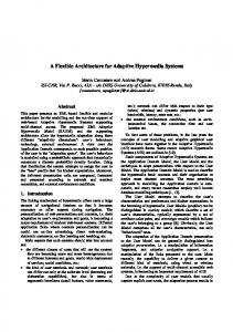
3 The safety architecture of the microcontroller The MCU described in this paper uses an optimized combination of safety mechanisms, as summarized in Figure 1. The backbone of the safety architecture is implemented using a library of Intellectual Properties (faultRobust IPs or fRIPs). They are architectural and functional diverse with respect to the MCU sub-block that they supervise: in this way, common-cause failures are intrinsically reduced without the need of additional layout/HW measures. Functional safety is guaranteed for the complete subsystem, i.e. latent faults (such as faults in the safety mechanisms that could mask a fault in the supervised logic) are detected thanks to HW/SW checking circuitry implemented in each fRIPs. Moreover, they deliver detailed diagnostic information, such as type of error (load/store fault, register fault, memory bit flip, bus matrix fault) and context information (last instruction executed without errors, address of faulty location, bus slave addressed during the fault, etc…). fRBUS
MCU CPU Memory
ThwD
Peripheral
.....
..... Peripheral
Safety mechanisms
CPUs
fRCPU
memories
fRMEM
busses
fRBUS
peripherals
ThwD
diagnostic
fRNET
fRMEM
fRCPU
Optimized Tightly Coupled (OTC) fault supervisor
sub-systems
ThwD
Peripherals Safety Mechanisms
infos fRNET
Fig. 1. The safety mechanisms used in the microcontroller
The fRCPU is an “optimized tightly coupled fault supervisor”. It supervises the “inner” CPU core but also “outer” core (such as memory protection unit, interrupt controller and bus matrix) and checking unintentional activation of the internal debug logic. It is “optimized” because fRCPU follows the same instruction flow as the CPU but its architecture is optimized to supervise only the portion of the CPU logic leading to failures (identified with the fRFMEA process described in previous section). It is “tightly coupled” because fRCPU takes benefit of a dedicated interface (agreed with the CPU vendor) by which fRCPU monitors the CPU inner portion increasing the diagnostic coverage and decreasing the detection latency. Main blocks of fRCPU are: the Sniffer Unit collecting, comparing and coding signals from the CPU boundary; the Shadow Processing Unit executing the same instruction flow of the CPU, including a register bank to store a shadow value of CPU main registers; a Management Unit to generate data/addresses. fRCPU compares its results with the ones read from the protected CPU by means of a set of independent checkers supervising the different CPU ports. The fRBUS supervises the multilayer bus included in the MCU. It is mainly composed by a set of “scoreboards”, one for each bus master and slave to be supervised, plus a central supervisor comparing expected and measured values. As
required by IEC 61508, both arbitration, decoding (addresses) and data transport (interconnect matrix) are monitored. Enhanced multiple bits error detection capability is provided, including measures to detect loss of power supply. fRMEM details can be found in [14] and [15]. For peripherals, the MCU includes dedicated safety mechanisms called “ThWD” (TOSHIBA hW diagnostic): Figure 2 shows how an example for the supervision of Operating System Timers. According to IEC 61508, the failure modes to be supervised are: counter failure, register failure, clock failure, capture failure and timer comparator failure. To match those requirements, a redundant counter structure has been implemented. Moreover, parity bits have been included in registers to detect register failures. In cooperation with a SW routine, both clock, capture and comparator failures are detected. The fRNET collects all the alarms and failures information generated by the other fRIPs as also by the “ThWD”. It provides fast signaling of errors coming from fRIPs with a double-rail OK/NOK global error signal. It has a simple supervisor command interface to access fRIPs diagnostic information and fRNET status, with targeted and broadcast command dispatching. It includes automatic checking (BIST) logic to detect latent faults inside fRNET and to test error signals paths. OSC
Parity
Compare register 2 PLL Comparator Clock Generator
Sysclk
÷M 4 Latch
3 ÷N Refclk Redundant Oscillator
5
Match
1
Latch
Double counter with
Alarm
some special logic
Counter Parity
Capture register
Capture register
2
H/W detection 1. Counter failures 2. Register failures Detection by co-operation of H/W and S/W 3. Clock failures 4. Capture failures S/W detection 5. Comparator failures
Fig. 2. The safety mechanism implemented for the Operating System Timer.
Figure 3 shows the architecture of the MCU as it has been implemented in a “Target Chip”, composed by two “channels” including each one a CPU (ARM Cortex-M3 CPU), FLASH, SRAM and a local bus. All the blocks of the vital cores have been supervised by fRIPs and ThWD. The two channels shares a Shared SRAM and some key peripherals: this shared area is also supervised by fRIPs and ThWD. Using the methodology described in section 2, the SFF was computed (see Table 2) demonstrating that the MCU is able to reach SIL3. In terms of absolute values, a Probability of Failure per Hour (PFH) of less than 0.2 FIT has been computed with fRMethodology: results have been validated using a massive campaign of fault injection in which millions of permanent and transient faults have been injected. For example, for the Operating System Timers, several test benches were used to stimulate all the timer functions: configuration, pre-scaler setting, counting, set/clear, matching, interrupts, etc. Faults were injected in both Timer and related fault supervisor (ThWD). Concerning permanent faults, all possible stuck-at faults were injected at gate-level (more than 12K faults); moreover a “N-detect” fault injection
method was used, with N>10, to consider fault models of deep-sub-micron technologies such as stuck-on / stuck-open [16]. Bridging faults were injected for nets selected based on layout information. Concerning transient faults insertion, bit-flips were injected in every timer registers while transient faults in the combinational logic (SET, single event transients) has been considered in the fRMethodology model. 64KB
512KB
8KB
BTROM
fRMEM
Flash
fRMEM
fRMEM
SRAM
64KB
512KB
SRAM
Flash
fRMEM ThwD
ThwD
AHB-Lite Bus
DMAC
fRBUS
fRMEM
CPU
fRCPU
(Cortex-M3)
DMAC
AHB-Lite Bus AHB-Lite Bus 16KB
Exclusive control
Shared SRAM
CAN
ThwD
fRNET
CPU
(Cortex-M3)
AHB-Lite Bus
fRBUS
ThwD
fRCPU
fRBUS
8KB
BTROM
ThwD
ThwD
OSTimer
TEST ThwD
AHB | APB Bridge ThwD
16KB
WDT ThwD
OSTimer
ThwD
PWM TIMER
UART SEIO
ThwD
ADIF
GPIO
Shared SRAM
fRMEM
FlexRay
ThwD
CG RESC
ThwD
Fig. 3. The “Target Chip”. Each channel is able to reach SIL3 by itself. Table 2. Safe Failure Fraction metrics measured for the microcontroller. Besides the overall SFF, it is shown: the SFF related to the “mission logic” only (i.e. excluding the faults in the safety mechanisms), the SFF related to “active” safety mechanisms (e.g. ECC); the SFF related to “passive” safety mechanisms (e.g. supervisors like fRCPU, to consider latent faults)
with memories memories excluded
SFF (target 99%) 99.84% 99.28%
SFF Mission (target 99%) 99.84% 99.11%
SFF Active diag. SFF Passive diag. (target 99%) (target 90%) 99.25%
96.54%
Figure 4 shows the error handling strategy of the proposed MCU, achieved thanks to the detailed diagnostic information provided by the fRIPs. In case a fault is detected by one of the fRIPs (e.g. fRCPU), the fRNET is informed and diagnostic information are read. Based on the (configurable) severity of the occurred error, the MCU can directly switch to an hard-wired safe-state (in which all the outputs are fixed to a safe value) or it can continue the operations by using the diagnostic information (e.g. which instruction went wrong, which CPU registers were corrupted etc) to implement SW-based recovery/retry tasks and restarting the operations without entering the safe-state. The possibility to “quickly and cleanly” restart the fRCPU is one of the key advantage of the proposed architecture compared to dual-core lockstep, because it always requires a full reset of the lock-step pair after a detection of a fault (otherwise the alignment is lost): that reset procedure will easily take several ms and therefore the availability could be seriously affected.
ARM Cortex-M3 + fRCPU is OK
Fault
fRCPU_armcm3 detection
Configurable severity: error, warning or info
fRCPU_armcm3 alarm generation
Configurable if error, warning or info lead to alarm setting
fRNET alarm generation
Interrupt
Examples: which instruction SW reads went wrong, diagnostic infos which CPU through fRNET registers were corrupted, if the SW-based fault was during recover/retry a load or store using diagnostic etc... info
configurable if interrupt or reset
Internal reset
Safe-state
fRCPU_armcm3 restart
Fig. 4. Error handling strategy
The first picture of Figure 5 shows how the proposed architecture allows the implementation of a fail-safe behavior without the need of complex external supervisors: in case the fRIPs or ThWD are detecting a fault, the fRNET can switch the actuator in a safe configuration (e.g. shut-down or reset). Afterwards, the CPUs – according the previously described error handling strategy – could check if the fault was permanent or transient and in case the error was transient, the fRNET could release the control of the actuator and continue the operation. Otherwise the MCU will be kept in reset. The key advantage of the proposed architecture is the group of measures (such as functional diversity, clock supervision, special layout measures for reset and clock distribution, logic for detection of “all zeroes” power fault models, proper placing of alarm pads) implemented to avoid common-cause failures, removing the need of complex diverse external components. MCU fRCPU
CPU
reset or interrupt
fRCPU
fRCPU
CPU (ARM Cortex-M3)
CPU (ARM Cortex-M3)
alarm to the upper level
fRBUS
PERI
BUS MEM fRMEM
fRNET
infos
PERI shut-down actuator
S
A
Application Channel Core A
Assistant Channel Core B
Fig. 5. Fail safe and fail operational architecture
The small gate count overhead of the fRCPU (less than 40% of the CPU gate count) allows the implementation of a fail functional architecture (second picture of Figure 5). Each channel is performing its own tasks and in case of a fault in one of the two cores, the other core can execute tasks of that core (reduced operation or fail graceful degradation). Or it can be used in a configuration in which both channels are performing the same tasks and in case of a fault in one of the two cores, the mission can be performed by the other channel (full fail operational, HFT=1).
4 Cost comparison with dual-core lock-step Figure 6 shows a comparison, in terms of gate count, between the dual-core lockstep concept and the proposed architecture. The dual-CPU lock-step architecture is unable to reach SIL3/ASILD without additional measures. This is caused by the potential for common cause failures affecting both CPUs which cannot be detected by the compare unit. Therefore, the dual-CPU lock-step architecture has got a βASIC greater than 50%. HW measures required to lower the βASIC are listed in IEC 61508: they include the use of an external watchdog, diverse synthesis for the CPU checker, specific layout requirements (e.g. using guard-rings ≥ 100μm and a potential ring), and temperature sensors. IEC 61508 also requires a minimum diagnostic coverage of each CPU of at least 60%. Therefore proper SW routines are needed such as CPU start-up and periodic diagnostic tests, CPU compare unit management and failure diagnostic and control. Our proposed architecture on the other hand requires no additional measures to fulfil IEC 61508 thanks to the intrinsic diversity of the fRIPs and due to the detailed analysis done with fRFMEA as described in section 2. Moreover, the fRCPU has a gate count significantly smaller than the supervised CPU: in the case of the Target Chip, the fRCPU shows a -58% of gate count with respect to the ARM Cortex-M3 CPU Core. The resulting cost for Optimized Tightly Coupled (OTC) fault supervisor is therefore only about 24% of the cost of diagnostic for a dual-core lock-step. Proposed method
dualcore lockstep
+69%
Optimized Tightly Coupled fault supervisor (OTC)
Measures to avoid common-cause failures Comparator, timeout
CPU-slave +100%
+100%
ARM-CM3 100.0%
CPU-slave +100%
ARM-CM3 100.0%
+169% COST of DIAGNOSTIC
fRCPU_armcm3 aux. features +2.9%
fRCPU_armcm3 +38.8%
+41,7% COST of DIAGNOSTIC
ARM-CM3 100.0%
Fig. 6. Gate count comparison
The same advantage is reflected on power saving: the fRCPU has a power consumption