Iván Martínez-Ortiz, Pablo Moreno-Ger, José Luis Sierra-Rodríguez, ... features related to its machine processing capabilities and the high level abstraction to.
A Flow-Oriented Visual Language for Learning Designs Iván Martínez-Ortiz, Pablo Moreno-Ger, José Luis Sierra-Rodríguez, and Baltasar Fernández-Manjón Department of Software Engineering and Artificial Intelligence Facultad de Informática, Complutense University of Madrid C/ Profesor José García Santesmases s/n, 28040 Madrid, Spain {imartinez,pablom,jlsierra,balta}@fdi.ucm.es
Abstract. Educational Modeling Languages (EMLs) are notations that allow instructors to describe teaching and learning interactions and activities in a formal way. This description of a specific teaching process is called a Unit of Learning (UoL). The main advantage of UoLs described using EMLs is that they can be automatically orchestrated using an interpreter that coordinates all the activities defined in the UoL. The advantages of this approach in terms of scalability and interoperability are great but, in practice, its application is being hindered by different problems such as the technical skills required to use these languages and the difficulty of understanding preexisting UoLs. In order to allow the widespread adoption of EMLs, it is necessary to reduce steep learning curves that prevent instructors from using them. In this work we present the graphical notation used in the e-LD approach, a methodology which promotes the adoption of EMLs simplifying the authoring process of new and preexisting UoLs. Keywords: Educational Modeling Languages, Learning Design, Graphical authoring.
1 Introduction For the last few years, e-learning has been a very active research field with real application in industry and educational institutions. Even though e-learning has been successful in many cases, a number of limitations have been identified and have attracted criticism. One of the key issues identified is that e-learning environments are too focused on learning content to be consumed by the learners. However, an effective learning process requires more than simply being exposed to content. It should also include other activities such as completing exercises, preparing essays, discussing topics, assessing progress, etc. These activities reinforce the knowledge contained in the content. Usually, when teachers or domain experts design a course, they decide which content should be included, which activities should be performed and in which order these activities should happen to achieve effective learning. In other words, teachers must design a teaching method. The definitions of these teaching methods, referred to hereafter as learning designs, include the goals and scope of the course, methods for evaluation, and different course modules (e.g. contents). An explicitly written learning design can be used for different purposes. For example it may be validated by a quality department before F. Li et al. (Eds.): ICWL 2008, LNCS 5145, pp. 486 – 496, 2008. version: See http://www.e-ucm.es/publications/articles.html for updated citation information ©Draft Springer-Verlag Berlin Heidelberg 2008
A Flow-Oriented Visual Language for Learning Designs
487
the course is deployed, or it may be reviewed by students before enrollment. Traditionally, this documentation task is performed by creating descriptive documents using natural language. Nevertheless, learning designs can be formally described using suitable Educational Modeling Languages (EMLs). Currently the most widelyextended formal EML is IMS Learning Design (IMS LD) [5,6]. From a pedagogical perspective, an EML is a notation that teachers or instructors can use to formalize the learning designs that they have in mind. The formal approach, as opposed to using natural language, allows the automatic processing of these designs by a computer system. From a technical perspective, the EML can also be seen as a scripting language for Learning Management Systems (LMSs) that allows the configuration of the learning experiences on these systems. But contrary to traditional programming languages created for technical staff, the intended target audience of EMLs are teachers and instructors. However, the application of EMLs is not devoid of problems. A formal EML should be carefully designed in order to provide a balance between the expressivity features related to its machine processing capabilities and the high level abstraction to simplify its application by humans. IMS LD, for example, is a powerful EML but its use in practice is being hindered by different problems such as its large expressiveness and the technical skills needed for its application, which are far beyond the reach of most real users without mature user-friendly supporting tools. To address this complexity-expressiveness balance, our approach is to make a conceptual distinction between two kinds of EMLs: exchange EMLs and authoring EMLs. Exchange EMLs have a large expressiveness and include low level characteristics that are not very relevant for the instructor. They are closer to the machine level, effectively becoming a low-level abstraction tool for e-learning applications, allowing the customization of any compliant e-learning platform to suit specific needs. In this sense, IMS LD should be classified as an exchange EML. On the other hand, authoring EMLs have a more restricted expressiveness but are closer to instructors' needs and ways of thinking. Because authoring EMLs are specifically adapted to instructors’ expertise, authoring and repurposing tasks are far more affordable for nontechnical instructors. Our approach, called e-LD, proposes a collaborative process model for the domainspecific EML authoring design. This process involves not only instructors but experts in computer science who provide support to instructors during the authoring process as well. In our opinion, in order to facilitate the use of EMLs by teachers and instructors, it is necessary to provide graphical abstractions, which are more user-friendly than the terse XML syntax usually provided in EML specifications. These abstractions are closer to the needs of the user, and then can be translated to the more machinefriendly notations of exchange EMLs via importation/exportation processes. In this paper we describe the visual language used in our e-LD approach. The notation includes concepts closely related to IMS LD, which is our target exchange EML. However, it is simple-enough to be useful for instructors, allowing them to produce and maintain their learning designs. The rest of this paper is organized as follows. Section 2 introduces the graphical notations used in the diagrams created during the authoring process. Section 3 describes
Draft version: See http://www.e-ucm.es/publications/articles.html for updated citation information
488
I. Martínez-Ortiz et al.
a use case of the e-LD approach and particularly of the visual notation. Finally, we provide some conclusions and outline some lines of future work.
2 Graphical Notations for UoL Authoring The use of graphical notations to provide a visual syntax for modeling languages has been tested and put into practice in many different domains. Some examples include databases with Entity-Relationship models for defining database schemas [13], software engineering with Unified Modeling Language (UML) for describing software systems [3], and business application with Business Process Management Notation (BPMN) for describing business processes [1]. These graphical notations have been developed to simplify the cognitive load when working with complex semantic models. They provide a simpler notation that can be more clearly understood by a wide range of users, from technical to non-technical staff. Following this trend, we propose the use of graphical notations for the design of UoLs [8]. These notations include: − A notation for Learning objectives. This notation allows an instructor to define which goals (learning objectives) will be covered in the UoL. For this purpose the instructor can define a high level goal that will be the overall objective and later on refine this objective into sub-objectives that will be achieved in the different parts of the UoL. Also, with this type of notation, it is possible to define the actors involved in reaching these goals (e.g. student, teacher). − A notation for defining activities. This notation contemplates the definition of the different activities to be performed during the execution of the UoL. Using this notation, instructors analyze which activities are needed to reach the learning objectives. Then they design activities describing what is to be done and which tools (chat, dossier, laboratory tool, etc.) should be used. These activities will also include the instructions and the resources (learning contents and tools) needed to perform them. Activities can be classified into simple and structured ones. Simple activities are typically performed by students with or without the help of an instructor. Structured activities aggregate simple activities adding an implicit runtime behavior. As structured activities can be very large and complex the notation introduces hierarchical abstraction facilities. − A notation for sequencing activities. By using this notation, instructors make explicit the learning flow through the different activities that comprises the UoL. In addition, the notation allows the roles to be involved in the activities to be defined. Sequencing definitions can be a simple ordering of activities applied to all participants, or can be a personalized definition of the learning flow based on the performance of a particular participant during the execution of the UoL. The definition itself can be verbose. Therefore, the notation also introduces hierarchical decomposition mechanisms. This decomposition involves at least two levels: the first one defines the overall structure (course modules) and the second provides a precise definition of the sequencing of these different parts. All these notations coexist in a unified, flow-oriented, view of the learning design, which integrates all the aspects of this design. This single unified view avoids unnecessary cross-references between information elements which are usually used only in Draft version: See http://www.e-ucm.es/publications/articles.html for updated citation information
A Flow-Oriented Visual Language for Learning Designs
489
one place. This feature, together with a carefully designed visual aspect, should increase the usability of the notations with respect to more exchange-oriented ones (such as IMS LD). The following subsections go inside the different notations which constitute the unified flow-oriented view. 2.1 Notation for Describing Learning Objectives The notation for describing Learning Objectives is a diagram that allows the definition of the learning objectives to be covered in the UoL. In addition, this notation can include the definition of which role will be involved during the achievement of the learning objectives. Each learning objective definition includes a verbose textual description which can be attached to the graphical representation.
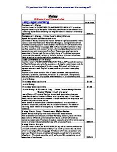
Fig. 1. Example of a learning objectives definition with role association
Fig. 1 shows an example of this notation. This example contains two objectives OBJ 1 and OBJ2 represented with ellipses. In addition, OBJ 2 is subdivided into a graph of sub-objectives using a dashed arrow. In the figure two roles have been defined: STUDENT (a learner role) and TEACHER (a staff role) represented as stickmen. These roles are associated to learning objectives using lines between the stickman and the objective. It should be pointed out that the association between actors and objectives is inherited by sub-objectives, which means that the role associated to the main objective also participates in the achievement of the subobjectives. In our example, the TEACHER role is only involved in the achievement of OBJ 2.3 and OBJ 2.2.1 learning objectives, while the STUDENT role is involved in OBJ 1, OBJ 2 and in all the sub-objectives of OBJ 2 (i.e. OBJ 2.1, OBJ 2.2, OBJ 2.1.1 and OBJ 2.2.1). Note that it is also possible to design learning objectives for different learner roles because the notation for learning objectives is not restricted to only one learner role per diagram.
Draft version: See http://www.e-ucm.es/publications/articles.html for updated citation information
490
I. Martínez-Ortiz et al.
2.2 Notation for Defining Activities Fig. 2 depicts the graphical notation used in defining activities. Using a terminology borrowed from IMS LD, the notation introduces two kinds of activities: simple and structured: − Simple activities include learning activities (Fig. 2a) which are typically performed by students and support activities (Fig. 2b) which are performed by students too, but with the help of a supporting role, usually an instructor. − Structured activities allow instructors to aggregate simple activities adding an implicit runtime behavior. With these activities there are two possibilities: performance in sequence or allowing the actor to choose the order of performance. According to these possibilities, there are two different graphical notations for activity structures: Fig. 2 (c) shows the appearance of a structured activity with a sequencing runtime behavior and Fig. 2 (d) shows the appearance of a structured activity with a random selection behavior. (a)
(b)
(c)
(d)
ACTIVITY
ACTIVITY
ACTIVITY 1
ACTIVITY STRUCTURE
ACTIVITY 2 ...
ACTIVITY A
ACTIVITY N
ACTIVITY X
ACTIVITY G
Fig. 2. Notation for simple activities and structured activities
Due to the hierarchical nature of activity structures the proposed graphical notation also allows for the definition of activity structures in separate diagrams. ACTIVITY 2 in Fig. 2 (c) and ACTIVITY G in Fig. 2 (d) show a pitchfork symbol as an annotation of this behavior. However, it is also possible to define a whole complex structured activity in the same diagram. All activities, whether simple or structured have a set of non-visual properties allowing the complete definition of the activity. For example this definition includes the linking of the activity with the resources that will be available during its performance or the description of the learning objectives that will be achieved after the performance of the activity. 2.3 Sequencing Notation Sequencing diagrams have similarities with UML Activity diagrams [3]. However, in contrast with works like [7], we are not attempting to use UML as a learning design
Draft version: See http://www.e-ucm.es/publications/articles.html for updated citation information
A Flow-Oriented Visual Language for Learning Designs
491
notation, but simply use activity diagrams as a natural choice in a flow-oriented modeling domain. Our notation also includes many other elements and concepts which have nothing to do with standard UML. Fig. 3 depicts a repertory of symbols used in the e-LD sequencing diagrams. Hence there is a notation for indicating: − The starting (Fig. 3a) and ending (Fig. 3b) points of the diagram. − The different learning flows represented by arrows (Fig. 3c). − Parallel execution of elements (Split element in Fig. 3d). Using this notation, a single learning flow can be divided into different parallel learning flows. − Synchronization of several threads of execution (Join element in Fig. 3e). Whenever the learning flow is divided, synchronization of the learning flows is needed to reunify the learning flow as well. − Assignment of participant roles to activities (Fig. 3f-g). Activity sequencing diagrams can be partitioned to specify which roles will be involved in the performance of the activities. (d) (a)
(b)
(e)
(f)
(c)
(g) STUDENT
ROLE1, ROLE2
Fig. 3. Symbols used in sequencing diagrams
Activities, whether simple or structured, will appear in activities sequencing diagrams using the same notation as described in section 2.2. In addition the concept of module is introduced in activity sequencing diagrams to ease the authoring of complex sequencing learning flows. Fig. 4a represents a module, whereas Fig. 4b represents quite a common structure used during sequencing where Fig. 4c is its compact representation. (a)
(c)
(b) MODULE 1
MODULE 1
...
...
MODULE
MODULE N
MODULE N
Fig. 4. Notation for play IMS LD concept
The graphical shape for modules is quite similar to the simple activities shape. Note that, just like structured activities, the pitchfork symbol can appear in the module graphical notation indicating that a detailed description is represented in a separate diagram.
Draft version: See http://www.e-ucm.es/publications/articles.html for updated citation information
492
I. Martínez-Ortiz et al.
2.3.1 Advanced Sequencing: Personalization of the Learning Flow To facilitate the personalization of the learning flow based on the evolution of the learner during the performance of the UoL, e-LD’s sequencing notation incorporates conditions. Conditions are also present in mainstream exchange languages, such as IMS LD. However, the way of incorporating conditions in e-LD is radically different from IMS LD. In IMS LD, conditions are not directly linked to the learning flow, but appear as a separate set of reactive rules, which are also available for all the activities. This feature makes the IMS LD level B very difficult to use and maintain. Even computer science experts without an advanced knowledge in rule-based computation systems (a computation model often used in contexts such as artificial intelligence programming [4]) have difficulties using it, let alone an average instructor. By contrast, in e-LD, conditions are integrated into the learning flow, and they are restricted to their occurrence in the diagram. This integration increases the usability of the notation, since now instructors are not required to think about a disaggregated set of rules defined in another portion of the design. They only need to reason out each relevant point in the natural evolution of a learning flow, which is a far lower cognitive load. (b) condition node
(a) [exp]
[exp 1]
(c) [else] [exp 2]
[else]
[else] [exp]
then branch else branch
(d) merge node [exp]
Fig. 5. Notation for conditional sequencing
Fig. 5 depicts the graphical notation for conditions: − Fig. 5 (a) shows an example of an if-then-else condition rule definition. The flow between activities is guarded by expressions like [exp]. That is, the activity that has a guarded incoming arrow will not be performed if the guard expression becomes false. There is a special guard condition [else] that can be used to mark that this flow will be followed if the guarding expression becomes false). − Fig. 5 (b) shows an example of a condition definition where if-then-else rules are nested supporting a detailed learning flow definition. − Fig. 5 (c) shows an example of a condition which only contains the then part. If it is only one branch Fig. 5 (d) notation can be used instead. In turn, Fig. 6(a) depicts an example of the graphical notation for conditions. The example scenario involves two activities ACTIVITY 1 and ACTIVITY 2 where these two activities will be performed by a student. However ACTIVITY 2 starts when the expression becomes true. Fig. 6(b) provides an excerpt of the IMS LD XML equivalent to support the graphical notation depicted in Fig. 6(a), which is illustrative of the economy of the graphical notation depicted. Draft version: See http://www.e-ucm.es/publications/articles.html for updated citation information
A Flow-Oriented Visual Language for Learning Designs
493
3 Use Case Scenarios The graphical notation included in e-LD and described above has been successfully tested in two different scenarios: with advanced users (the development team from the e-LD platform) and with PhD students from an e-learning course offered at the Complutense University To test and improve the notation the development team used a pool of well-known UoLs already created including: − All the examples provided in the best practices document of the IMS LD specification. − Some popular examples developed by the Open University of the Netherlands available in dspace.learningnetworks.org, such as Candidas II, Geoquiz 3, Learning to listen to Jazz and QuoBuilder 2.
(a)
(b) STUDENT
ACTIVITY 1
[exp]
ACTIVITY 2
ACTIVITY 1 ACTIVITY 2
Fig. 6. Example of notation and IMS LD XML excerpt
Draft version: See http://www.e-ucm.es/publications/articles.html for updated citation information
494
I. Martínez-Ortiz et al.
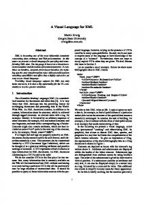
As an example of UoL authoring, Fig. 7 shows an excerpt of the visual specification diagram corresponding to the Learning to listen to Jazz UoL. This is a relevant example involving IMS LD Level B features, since it addresses adaptability based on student decisions and actions. This example also provides a simple learning style evaluation, which is incarnated in how the learning path best suited for the learner’s style is recommended by the UoL. In addition, the example shows how the progress on the UoL is based on the result of the work that is done in the activities. Act (Play 1) c student
teacher
Before you start
Monitor student progress
some information about you
orientation [id-D996B9E6-4EA2-11D5-8D44-0004AC39A2F5=‘historical’] [id-D996B9E6-4EA2-11D5-8D44-0004AC39A2F5=‘thematic’]
Historial route
thematic route
[historicalRouteComplete=1]
Final reflection
[id-D996BA21-4EA2-11D5-8D44-0004AC39A2F5+ id-D996BA22-4EA2-11D5-8D44-0004AC39A2F5+ id-D996BA23-4EA2-11D5-8D44-0004AC39A2F5+ id-D996BA24-4EA2-11D5-8D44-0004AC39A2F5>4]
c
Fig. 7. Excerpt of the Learning to Listen Jazz UoL diagram with the e-LD notation
4 Conclusions and Future Work In this paper we have presented an EML visual notation specifically oriented to simplify UoL authoring. However, it is important to note that we are not promoting yet another new EML. The key idea is to use this author-oriented notation for the authoring process, and then translate the designs to the more machine-oriented notations of standard EMLs (e.g. IMS LD) through importation/exportation processes. As a result of the preliminary experiments we think that the graphical notation proposed simplifies the process of authoring UoLs. The creation of UoLs of the complexity of those analyzed in our practical experiments is a feat beyond the reach of most designers, but students without a previous background in using EMLs were able to recreate them using e-LD. However, further study is required, especially in reuse scenarios, where non-experts create new UoLs based on UoL templates or previously built UoLs.
Draft version: See http://www.e-ucm.es/publications/articles.html for updated citation information
A Flow-Oriented Visual Language for Learning Designs
495
Readers familiarized with the UML graphical notation will notice several parallelisms with the notation described in this work. This is intentional, given the background in Computer Science of the participants in the test case. However, different notations can be developed or customized for a particular stakeholder or community. Indeed, the e-LD authoring language is built using model-driven development principles [12]. On the one hand, it includes a semantic model, which characterizes the kind of structures that make up a learning design. This model is the base for different graphical models, which can be related with the semantic model using model transformations (see [12] for more details). The graphical notation presented in this paper is just one of these graphical models. Our main short-term goal is to test the e-LD approach, and in particular the presented e-LD graphical notation with field users, particularly with the staff of the Spanish National Center for Information and Educative Communication (CNICE) to provide them with a support tool to help them in the design of educational templates. It will allow them to create their documentation using the e-LD’s authoring tool and to use the diagrams as an explanation of the sequencing of activities. As future work, we will also explore the compatibility with other exchange EMLs like SCORM Sequencing and Navigation [2] and whether it is possible to integrate at design time the authoring of UoLs using IMS LD and SCORM.
Acknowledgements The Spanish Committee of Science and Technology (projects TIN2005-08788-C0401, FIT-350100-2007-163 and TIN2007-68125-C02-01) has partially supported this work, as well as the Regional Government of Madrid (grant 4155/2005) and the Complutense University of Madrid (research group 921340 and Santander/UCM Project PR24/07 – 15865) and by the EU Alfa project CID (II-0511-A).
References 1. Aalst, W., Kees, H.: Workflow Management: Models, Methods, and Systems. MIT Press, Cambridge (2004) 2. Advanced Distributed Learning (ADL), Shareable Content Object Reference Model (SCORM) 2004 3rd Edition Sequencing and Navigation Version 1.0 (2006) 3. Booch, G., Rumbaugh, J., Jacobson, I.: The Unified Modeling Language User Guide, 2nd edn. Addison-Wesley, Reading (2005) 4. Brownston, L., Farell, R., Kant, E., Martin, N.: Programming Experts Systems in OPS5: An Introduction to Rule-based Programming. Addison Wesley, Reading (1985) 5. IMS. IMS Learning Design Information Model Version 1.0 (2003)(retrieved, July 12, 2007), http://www.imsglobal.org/learningdesign/ldv1p0/imsld_infov1p0. html 6. Koper, R., Tattersall, C. (eds.): Learning Design - A Handbook on Modelling and Delivering Networked Education and Training. Springer, Heidelberg (2005)
Draft version: See http://www.e-ucm.es/publications/articles.html for updated citation information
496
I. Martínez-Ortiz et al.
7. Laforcade, P.: Graphical Representation of Abstract Learning Scenarios: the UML4LD Experimentation. In: Advanced Learning Technologies ICALT 2007, July 18-20, 2007, pp. 477–479 (2007) 8. Martínez-Ortiz, I., Moreno-Ger, P., Sierra-Rodríguez, J.L., Fernández-Manjón, B.: Supporting Authoring and Operationalization of Educational Modelling Languages. Journal of Universal Computer Science 13(7), 938–947 (in press, 2007) 9. OMG. Unified Modeling Language: Superstructure version 2.1.1 (2007)(retrieved, July 10, 2007), http://www.omg.org/cgi-bin/doc?formal/07-02-05 10. OMG. Unified Modeling Language: Infrastructure version 2.1.1 (2007b)(retrieved, July 10, 2007), http://www.omg.org/cgi-bin/doc?formal/07-02-04 11. Paquette, G., Léonard, M., Lundgren-Cayrol, K., Mihaila, S., Gareau, D.: Learning Design based on Graphical Knowledge-Modeling. Educational Technology & Society 9(1), 97– 112 (2006) 12. Stahl, T., Voelter, M., Czarnecki, K.: Model-Driven Software Development, Technology, Engineering, Management. Wiley, Chichester (2006) 13. Chen, P.P.: Database Design Using Entities and Relationships. In: Yao, S.B. (ed.) Principles of Data Base Design, pp. 174–210. Prentice-Hall, NJ (1985)
Draft version: See http://www.e-ucm.es/publications/articles.html for updated citation information