A Formal Software Synthesis Approach for Embedded Hard Real-Time Systems Raimundo Barreto Mar´ılia Neves
Meuse Oliveira Jr Paulo Maciel
{rsb,mnoj,eagt,mln2,prmm}@cin.ufpe.br
Centro de Informatica ´ Universidade Federal de Pernambuco 50732-970 PO Box 7851 Recife-Brazil
Eduardo Tavares Ricardo Lima
[email protected] Escola Politecnica ´ Universidade de Pernambuco 50751-460 Praça Internacional Recife-Brazil
ABSTRACT
1.
Software synthesis is defined as the task of translating a specification into a software program, in a general purpose language, in such a way that this software can be compiled by conventional compilers. In general, complex real-time systems rely on specialized operating system kernels. However, the operating system usage may introduce significant overheads as in execution time as in memory requirement. In order to eliminate such overheads, automatic software synthesis methods should be implemented. Such methods comprise real-time operating system services (scheduling, resource management,communication, synchronization), and code generation. Formal methods are a very promising alternative to deal with the complexity of embedded systems, and for improving the degree of confidence in critical systems. We present a formal approach for automatic embedded hard real-time software synthesis based on time Petri nets. In order to illustrate the practical usability of the proposed method, it is shown how to synthesize a C code implementation using a heated-humidifier case study.
Software synthesis has become a key problem in design of embedded hard real-time systems, since the software is being responsible for more than 70% of functions in such systems [11]. Software synthesis is defined as the task of translating a specification into a software program, in such a way that this software can be compiled by conventional compilers. In general, complex embedded real-time systems rely on specialized operating system kernels. However, operating systems may introduce significant overheads in execution time as well as in memory requirement. Software synthesis might be an alternative approach to operating systems usage, since it can generate tailored code for satisfying functional, performance, and resource constraints, and automatically generate runtime support (scheduling, resource management, communication, etc) customized for each particular specification. In order to guarantee that timing constraints are satisfied, scheduling plays an important role. There are two general approaches for scheduling tasks: runtime and pre-runtime scheduling. In runtime, schedules are computed on-line as tasks arrive, using a priority-driven approach. Usually, the scheduler does not have any knowledge about not yet arrived tasks. Such approach is considered flexible and can be adjusted according the environment changes. However, there are situations where such approach is not able of finding a feasible schedule, even if such a schedule exists [13]. The scheduling method presented here is a pre-runtime, where the schedule is computed entirely off-line, which can achieve 100% processor utilization, reduces context switching, its execution is predictable, and excludes the need for complex operating systems. In order to find a feasible pre-runtime schedule, this work uses state space exploration, since it presents a complete automatic strategy for verifying finitestate systems [5]. Taking into account such needs, the main contribution of this paper is to provide a formal approach for synthesizing a timely and predictable scheduled code. This paper is an extension of our previous works [3, 4], which present how to reach feasible schedules by using a time Petri net model on monoprocessor and multiprocessor systems, respectively.
Categories and Subject Descriptors D.1.2 [Programming Techniques]: Automatic Programming; D.2.2 [Design Tools and Techniques]: Petri Nets; D.2.4 [Software Engineering]: Software/Program Verification—Formal Methods
General Terms Design, Verification, and Performance
Keywords Software Synthesis, Hardware/Software Codesign Methodologies, Embedded Hard Real-Time Systems.
Permission to make digital or hard copies of all or part of this work for personal or classroom use is granted without fee provided that copies are not made or distributed for profit or commercial advantage and that copies bear this notice and the full citation on the first page. To copy otherwise, to republish, to post on servers or to redistribute to lists, requires prior specific permission and/or a fee. SBCCI’04, September 7–11, 2004, Pernambuco, Brazil. Copyright 2004 ACM 1-58113-947-0/04/0009 ...$5.00.
2.
INTRODUCTION
RELATED WORK
Xu and Parnas [12] present a branch-and-bound algorithm that finds an optimal pre-runtime schedule on a single pro-
cessor for real-time process segments with release, deadlines, and arbitrary exclusion and precedence relations. Despite the importance of their work, it does not present real-world experimental results. Abdelzaher and Shin [1] extended that work in order to deal with distributed real-time systems. This algorithm takes into account delays, precedence relations imposed by interprocess communications, and considers many possibilities for improving the scheduling lateness at the cost of complexity. Lin [7] proposes a software synthesis process where the scheduling is carried out at compile time. Specifications are written considering a C language extension, and translated into safe Petri nets. However, this approach does not consider timing constraints. Sgroi et al. [10] propose a software synthesis method based on quasi-static scheduling using free-choice Petri nets. After obtaining a feasible schedule, C code is generated by traversing a set of conflict-free Petri nets. That work does not deal with realtime constraints, which are left to a real-time operating system. Hsiung [6] presents a formal software synthesis based on Petri nets, mixing quasi-static scheduling, and dynamic fixed-priority scheduling. However, although applying dynamic scheduling, it is not shown how to add preemption in the proposed methodology. Amnell et al. [2] present a framework for the development of real-time embedded systems based on timed automata extended with real-time tasks. Their solution relies on a fixed-priority scheduling policy, which may not reach existent feasible schedules. This work uses a time Petri net formalism for system modeling in order to find feasible pre-runtime schedules, and for synthesize predictable and timely scheduled code. In addition, the use of Petri net analysis techniques allows one to check several system properties. We believe this work brings an important contribution since it opens up a new possibility for automatic code generation of real-time systems based on formal timed models.
3.
COMPUTATIONAL MODEL
Computational model syntax is given by a time Petri net [8], and its semantics by a timed labeled transition system. A time Petri net (TPN) is a bipartite directed graph represented by a tuple P= (P, T, F, W, m0 , I). P (places), and T (transitions) are non-empty disjoint sets of nodes. The edges are represented by F ⊆ (P × T ) ∪ (T × P ). W : F → N represents the weight of the edges. A TPN marking mi is a vector mi ∈ N|P | , and m0 is the initial marking. I : T → N × N, represents the timing constraints, where I(t) = (EF T (t), LF T (t)) ∀t ∈ T , EF T (t) ≤ LF T (t), EF T (t) is the Earliest Firing Time, and LF T (t) is the Latest Firing Time. A time Petri net extended with tasks is represented by PT = (P, CS). P is the underlying TPN, and CS:T ,→ T C is a partial function that assigns transitions with a task code. A set of enabled transitions is denoted by: ET (mi ) = {t ∈ T | mi (pj ) ≥ W (pj , t)}, ∀pj ∈ P . The time elapsed, since the respective transition enabling, is denoted by a clock vector ci ∈ N|ET (mi )| . The dynamic firing interval (ID (t)) is dynamically modified whenever the respective clock variable c(t) is incremented, and t does not fire. It is computed as follows: (ID (t) = (DLB(t), DU B(t)), where DLB(t) = max(0, EF T (t) − c(t)), DU B(t) = LF T (t) − c(t), DLB(t) is the Dynamic Lower Bound, and DLB(t) is the Dynamic Upper Bound.
Definition 3.1 (States). Let P be a time Petri net, M be the set of reachable markings of P, and C be the set of clock vectors. The set of states S of P is given by S ⊆ (M × C), that is, a state is defined by a marking, and the respective clock vector. F T (s) is the set of firable transitions at state s defined by: F T (s) = {ti ∈ ET (m)|DLB(ti ) ≤ min(DU B(tk ))∀tk ∈ ET (m)}. The firing domain for t at state s, is defined by the interval: F Ds (t) = [DLB(t), min (DU B(tk ))]. Definition 3.2 (Timed Labeled Transition System). A timed labeled transition system (TLTS) is a quadruple L= (S, Σ, →, s0 ), where S is a finite set of discrete states, Σ is an alphabet of labels representing actions, → ⊆ S×Σ×S is the transition relation, and s0 ∈ S is the initial state. The semantics of a TPN P is defined by associating a TLTS LP = (S, Σ, →, s0 ): (i) S is the set of states of P; (ii) Σ ⊆ (T × N) is a set of actions labeled with (t, θ) corresponding to the firing of a firable transition (t) at time (θ) in the firing interval F Ds (t), ∀s ∈ S; (iii) → ⊆ S × Σ × S is the transition relation; (iv) s0 is the initial state of P. Definition 3.3 (Reachable States). Let LP be a TLTS derived from a time Petri net P, and si = (mi , ci ) a reachable state. sj =fire(si , (t, θ)) denotes that firing a transition t at time θ from the state si , a new state sj = (mj , cj ) is reached, such that: (1) ∀p ∈ P, mj (p) = mi (p) − W (p, t) + W (t, p); (2) ∀tk ∈ ET (mj ): (i) Cj (tk ) = 0 (if (tk = t) ∨ (tk ∈ ET (mj ) − ET (mi ))), or (ii) Cj (tk ) = Ci (tk ) + θ, otherwise. Definition 3.3 states that the firing of a transition ti , at time value θi , in state (si−1 ), defines the next state (si ). Definition 3.4 (Feasible Firing Schedule). Let LP be a timed labeled transition system of a time Petri net P, s0 its initial state, sn = (mn , cn ) a final state, and mn = M F is the desired final marking. (t1 ,θ1 )
(t2 ,θ2 )
(tn ,θn )
s0 −→ s1 −→ s2 − − → sn−1 −→ sn is defined as a feasible firing schedule, where si = fire(si−1 , (ti , θi )), i > 0, if ti ∈ F T (si−1 ), and θi ∈ F Dsi−1 (ti ). The modeling methodology guarantees that the final marking M F is well-known since it is explicitly modeled.
4.
SPECIFICATION MODEL
The specification model is composed by: (i) a set of periodic preemptable tasks with bounded discrete time constraints; and (ii) intertask relations, such as precedence and exclusion relations. Let T be the set of tasks in a system. A periodic task is defined by τi = (phi , ri , ci , di , pi ), where phi is the initial phase (delay until the task is requested for the first time after the start of the system). When not specified, phi = 0; ri is the release time (time interval between the beginning of a period and the earliest time that an execution of task τi can be started in each period); ci is the worst case computation time required for execution of task τi ; di is the deadline (time interval between the beginning of a period and the time by which an execution of task τi must be completed
in each period); and pi is the period (fixed rate at which τi should be repeatedly executed). A sporadic task is defined by τk = (ck , dk , mink ), where mink is the minimum period between two activations of task τk . A task is classified as sporadic if it can be randomly activated, but the minimum period between two activations is known. Mok [9] has proposed a translation from sporadic to periodic tasks. A task τi precedes task τj , if τj can only start executing after τi has finished. A task τi excludes task τj , if no execution of τj can start while task τi is executing. If it is considered a single processor, then task τi could not be preempted by task τj . Each task τi ∈ T consists of a finite sequence of task c time units τi0 , τi1 , · · · , τi i−1 , where τij−1 always precedes τij , for j > 0. A task time unit is the smallest indivisible granule of a task, during which it cannot be preempted by any other task. A task can also be split into more than one subtasks.
5.
MODELING REAL-TIME SYSTEMS
Time Petri nets allow modeling of several situations present in most real-time systems. This section is just a summary. For more details, the interested reader is referred to [3]. Modeling Scheduling Period. The proposed approach schedules tasks into a schedule-period (or hyper-period), that is equal to the least common multiple (LCM) of the periods of the given set of tasks. Within the schedule-period (PS ), there are several tasks’ instances of the same task, where N (τi ) = PS /pi gives the instances of τi . For example, consider the following specification consisting of two tasks: τ1 = (0, 0, 2, 7, 8) and τ2 = (0, 2, 3, 6, 6). Therefore, PS = 24, implying that the two periodic tasks are replaced by seven new periodic tasks (N (τ1 ) = 3, and N (τ2 ) = 4) with identical period (PS ), where the timing constraints of task instances have to be transformed to consider that new period. When the period is not specified, it is considered that this transformation have been done. Figure 1 shows a TPN model for this specification. Arrival (T2)
Deadline-Checking (T2) td2 [6,6]
tph2 [0,0] P20
tmd2 [0,0] P27
P24
P22
Pproc
(a)
P1
P2
...
P3 computation [C,C]
proc-grant
release
end
Pproc
(b)
C
C P1
...
P3
P2 computation [1,1]
proc-grant
release
end
Pproc
(c)
P2
P1 release
P3 comp.seg1 [cs1,cs1]
proc-grant-s1
...
P5
P4 proc-grant-s2
comp.seg2 [cs2,cs2]
end
Figure 2: Modeling Scheduling Methods b) Deadline Checking. The methodology proposed uses elementary net structures to capture deadline missing. c) Task Structure. The block task structure models: release time, processor granting, computation (in accordance with the scheduling method), and processor releasing. trelease
tgrant-proc
trelease
tsequence
tcomp
A
B tcomp
tgrant-proc
Figure 3: Modeling Precedence (A PRECEDES B) Intertasks relations are modeled as follows: d) Modeling Precedence and Exclusion Relations. Figure 3 presents the precedence relation modeling applied to all-non-preemptive scheduling method. One can see that task B could not proceed until task A has finished. Figure 4 models the A EXCLUDES B relation, where the all-preemptive scheduling method is used.
3 tc2 [3,3]
tp2 [0,0]
tr2 [2,2]
ta2 [6,6]
P28
P26
P25
P23
P21 Pstart
4
Pproc
Task-Structure (T2)
tstart [0,0] P11
P13
P15
tc1 [2,2] P16
P18
tph1 [0,0] Arrival (T1)
CA
tfinal
...
Pproc
Task B P12
CA
Pexclusive
2 P10
tcomp
tgrant-proc
texcl
trelease
3 tp1 [0,0]
tr1 [0,0]
...
Pend
Task-Structure (T1) ta1 [8,8]
Task A
tend [0,0]
td1 [7,7]
...
CB
CB trelease
P17
P14
...
tgrant-proc
tcomp
tfinal
tmd1 [0,0]
Deadline-Checking (T1)
Figure 4: Modeling (A EXCLUDES B)
Figure 1: Petri net model with building blocks Modeling Scheduling Methods. Figure 2 shows three ways for modeling scheduling methods: (a)all-non-preemptive, (b) all-preemptive, and (c) defined-subtasks. Modeling Tasks. Figure 1 also shows three main building blocks for modeling real-time task. These blocks are: a) Task Arrival. The block arrival models the periodic invocation for all task instances in the schedule period (PS ). A transition tph models the initial phase and transition ta models the periodic arrival for the remaining instances.
6.
SOFTWARE SYNTHESIS APPROACH
This section presents the formal software synthesis approach. It shows methods for scheduling synthesis and code generation phases.
6.1
Pre-Runtime Scheduling
This subsection shows a brief comparison among runtime and pre-runtime approaches, how to minimize the state space size, and the algorithm that implements the proposed method.
ra
rb
rd
41
51
60
90
100
140
ra
rd
db
rc
dc re
dd
de
30
rb
11
90
100
A
D
B
(b) 0
C
B
0
de
dd
rc
A
(a)
dc re
db
41
51
D
E
E
C 60
da
150
161
da
A 140
161
1 scheduling-synthesis(S,MF ,TPN) 2 { 3 if (S.M = MF ) return TRUE; 4 tag(S); 5 PT = pruning(firable(S)); 6 if (|PT| = 0) return FALSE; 7 for each (ht, θi ∈ PT) { 8 S’= fire(S, t, θ); 9 if (untagged(S’) ∧ scheduling-synthesis (S’,MF ,TPN)){ 10 add-in-trans-system (S,S’,t,θ); 11 return TRUE; 12 } 13 } 14 return FALSE; 15 }
D
Figure 6: Scheduling Synthesis Algorithm Figure 5: Runtime versus Pre-runtime
6.1.1
Runtime versus Pre-runtime Approach
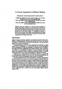
The runtime approach (static or dynamic priority based scheduling) may constrain the possibility of finding a feasible schedule, even if such a schedule exists. This situation is hardened when considering arbitrary precedence and exclusion relations. For instance, consider a task set consisting of five tasks, A, B, C, D, E, and the respective timing constraints: A = (0, 30, 161); B = (11, 30, 51); C = (60, 10, 90); D = (41, 10, 100); and E = (90, 50, 140). This specification also considers that B PRECEDES D, A EXCLUDES B, and A EXCLUDES D. Figure 5(a) shows that a runtime approach could not find a feasible schedule, since tasks B and E miss their deadlines. However, a pre-runtime approach finds a feasible schedule (Figure 5(b)). The same way as in previous example, the processor must be left idle between time 0 and 11, even though A’s release time is 0.
6.1.2 Minimizing State Space Size When generating TLTS of a TPN, tasks’ interleaving is the fundamental point to be considered when analyzing state space explosion problem. Furthermore, the analysis of n concurrent actions has to verify all n! interleaving possibilities, unless there are dependencies between these actions. This work proposes three ways for minimizing state space size: Modeling. The proposed method models dependencies between actions explicitly. For instance, resource granting and releasing, precedence and exclusion relations between tasks, markings representing properties to be avoided or verified,synchronization, etc. The modeling methodology itself aids in minimizing the state space size. Partial-Order. If actions can be executed in any order, such that the system always reaches the same state, these actions are independent. In other words, it does not matter in which order these are executed. Partial-order reduction methods are based on the independence of actions [5]. Independent actions are those that do not disable any other action when realized, such as: arrival, release, precedence, processor releasing, and so on. This reduction method proposes to give for each class of independent activities a different choice-priority level. The dependent activities, like processor granting, have lowest priority. Therefore, when changing from one state to another state, it is sufficient to analyze the class with highest choice-priority and pruning the other ones. When all independent activities are executed, certainly the final state is the same, because the order between them does not matter. This reduction is important
due to two reasons: (i) it reduces the amount of storage; and (ii) it finds quickly a negative result, when the system does not have a feasible schedule. Removing Undesirable States. In Section 5 it is presented how to model undesirable error states, for instance, states that represent missed deadlines. The method proposed is of interest for schedules that do not reach any of these undesirable states. When generating the TLTS, transitions leading to undesirable error states have to be discarded.
6.1.3
Pre-Runtime Scheduling Algorithm
The algorithm proposed (Fig. 6) is a depth-first search method on a TLTS. So, the TLTS is partially generated, according to the need. The stop criterion is obtained whenever the desirable final marking M F is reached. Considering that, (i) the Petri net model is guaranteed to be bounded, and (ii) the timing constraints are bounded and discrete, this implies that the TLTS is finite and thus the proposed algorithm always finishes. The only way the algorithm returns TRUE is when it reaches a desired final marking (M F ), implying that a feasible schedule was found (line 3). The state space generation algorithm is modified (line 5) to incorporate the state space pruning. PT is a set of an ordered pairs ht, θi representing for each firable transition (post-pruning) all possible firing time in the firing domain. The tagging scheme (lines 4 and 9) ensures that no state is visited more than once. The function fire (line 8) returns a new generated state (S 0 ) due to the firing of transition t at time θ. The feasible schedule is represented by a timed labeled transition system that is generated by the function add-in-trans-system (line 10). When the system does not have a feasible schedule, the whole reduced state space is analyzed.
6.2
Code Generation
Previous subsection shows how to find a feasible pre-runtime scheduling. This section aims to present the approach for code generation starting from the scheduling found. As presented before (Def. 3.4), the feasible firing schedule is expressed as a timed labeled transition systems. The code is generated by traversing the feasible firing schedule found, and detecting the time where the tasks are to be executed. Thus, the generated code can be seen as a cyclic executive, where the tasks are executed in accordance with previously computed schedule. The code for each task come directly from the code associated with computation transitions in the TPN model. It is worth noting that, in this software synthesis approach, just one timer is needed, since the gen-
erated code is already scheduled. Now, it is shown how to apply the proposed code generation approach in the example that has been conducted in this paper. Applying the proposed algorithm on the TPN model (Figure 1), it is generated a TLTS (not shown for lack of space). Analyzing the TLTS, it is found out that task T 1 is to be executed three times when the clock value is equal to 0, 11, and 17. The same way, task T 2 is to be executed four times, when the clock value is equal to 2, 8, 14, and 20. This information is stored in arrays (one array for each task) in the generated code. These arrays are accessed as a circular list. Figure 7 presents parts of the generated code. In this figure, it is shown the arrays definitions, the tasks calling, and the executive cyclic implementation. The timer definition is not shown.
Table 2: Specification for the Heated-Humidifier Task
r c
A (temp-sensor-start) 0 B (temp-sensor-handler) 11 C (PWM) 0 D (pulse-generator) 0 E (temp-adjust-part1) 0 F (temp-adjust-part2) 1501
1 1 8 4 1 2
d
p
1,500 1,500 1,500 4 5,000 5,000
10,000 10,000 10,000 20 10,000 10,000
Intertask Relations A PRECEDES B B PRECEDES C E PRECEDES F
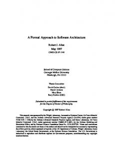
of electro-medical systems. For maintaining such vapor, the system must warm up the water in a recipient and maintain the water temperature in a prescribed value. This equipment is very useful in hospital’s critical care units (CCUs).
/* The timer counts from 0 up to 24 task time units */
.. . int i1, i2; int clk1[3], clk2[4];
.. .
Vcc
main() { clk1[0]=0; clk1[1]=11; clk1[2]=17; clk2[0]=2; clk2[1]=8; clk2[2]=14; clk2[3]=20; while (TRUE) { /* Task T1 */ if (clock==clk1[i1]) { task_T1; i1 = (++i1)%3; } /* Task T2 */ if (clock==clk2[i2]) { task_T2; i2 = (++i2)%4; } } }
electrical resistance
temperature sensor
7.
DOWN
Figure 8: Heated-humidifier architecture
Table 1: Experimental results summary Control Application Robotic Arm Xu (example 3) Xu (figure 9) Mine Pump Heated-Humidifier Unmanned Vehicle
8051 MICRO-CONTROLLER
A/D CONVERTER
Figure 7: Part of the generated code
Example
UP
instances state-min found time(s) 28 37 4 5 782 1505 433
50 50 150 150 171 1566 281 2387 3130 3255 6022 6022 4701 14761
0.001 0.014 0.121 0.222 0.462 0.486 2.571
EXPERIMENTAL RESULTS
Table 1 summarizes the application of the proposed scheduling methodology to several case studies. In that table, instances represent the number of tasks’ instances. state-min is the minimum number of states to be verified, found counts the number of states actually verified for finding a feasible schedule, and time expresses the algorithm execution time in seconds. All experiments were performed on a Duron 900 Mhz, 256 MB RAM, OS Linux, and compiler GCC 3.3.2. However, one of these examples, a heated-humidifier, is considered in order to depict the practical usability of the software synthesis method in more details. This control system inserts water vapor in the gaseous mixture used in a sort
The architecture can be seen in Figure 8, which consists of a micro-controller (8051), two keys for adjustment of the desired temperature, a temperature sensor, and an electric resistance (in a water recipient). Water warming is controlled by pulse width modulation (PWM) technique, which modulates (on/off) the power supplied to the electrical resistance. Table 2 shows part of the specification model. The values are expressed in time units, where each time unit (Section 4) is equal to 10µs. The deadline of tasks A and B take into account that, after A/D conversion, the sensor has to be read at most in 15ms. Tasks E and F consider that keys are kept pressed up to 50ms. In order to avoid the key bouncing, the key reading for temperature adjustment is divided into two tasks. If task E indicates that a key is pressed, after a specific minimal time (generally 15ms), the task F must confirm such key pressing. It is why the release time is equal to 1501 time units (1,500(key bouncing) + 1(execution of task E)). The same solution is applied for reading the temperature sensor. The first task (task A) is responsible for starting the A/D conversion. After elapsing a specific time (generally 100µs), the second task (task B) may start reading the temperature and updating a shared variable. Figure 9 presents an automatically translated TPN model for this task model, where a defined subtask scheduling method is used. For sake of simplicity, the processor is not modeled in this figure. This TPN model is used to search for a feasible scheduling. This schedule was found in 0.486
/* The timer counts from 0 up to 10000 time units */
start
Task A
Task D
Task C
Task B
Ph1
A1
Ph2
A2
Ph3
A3
Ph4
D1
R1
D2
R2
D3
R3
D4
C1
C2
Ph5
A5
Ph6
A6
R4
D5
R5
D6
R6
Md4
M3
Md2
A4
G4
G3
G2
G1
Md1
G6
G5
int i1, i2, i3, i4, i5, i6; int clk1[1], clk2[1], clk3[1], clk4[500],clk5[1],clk6[1];
Md6
Md5 C4
C3
.. .
Task F
Task E
while (TRUE) { /* Task T1 */ if (clock==clk1[i1]) { task_T1; i1 = (++i1)%1; } /* Task T2 */ if (clock==clk2[i2]) { task_T2; i2 = (++i2)%1; } /* Task T3 */ if (clock==clk3[i3]) { task_T3; i3 = (++i3)%1; } /* Task T4 */ if (clock==clk4[i4]) { task_T4; i4 = (++i4)%500; } /* Task T5 */ if (clock==clk5[i5]) { task_T5; i5 = (++i5)%1; } /* Task T6 */ if (clock==clk6[i6]) { task_T6; i6 = (++i6)%1; } }
C5
C6
end
Figure 9: Heated-humidifier time Petri net model seconds, verifying 6022 states, which is the minimum number of states to be verified. As presented in Section 6.2, C code is generated by traversing the feasible firing schedule returned by the scheduling synthesis framework. Figure 10 shows parts of the generated code.
.. . main() { clk1[0]=4; clk2[0]=11; clk3[0]=12; clk4[0]=0; clk4[1]=20;
.. . clk4[499]=9980; clk5[0]=5; clk6[0]=1504; }
8.
CONCLUSIONS
This paper proposed a formal methodology for embedded hard real-time software synthesis based on time Petri nets. Predictability is an important concern when considering time-critical systems. In order to guarantee that all critical tasks meet their deadlines, it is used the pre-runtime scheduling approach. In spite of the analysis technique (i.e. state space exploration) used in this work is not new, to the best of our present knowledge, there is no similar work reported that uses formal methods for modeling time-critical systems, considers arbitrary precedence/exclusion relations, and generates timely and predictable scheduled code. The proposed scheduling algorithm is a depth-first search method on a finite timed labeled transition system derived from a TPN model. When searching for a feasible schedule, the algorithm suffers from the state space explosion problem. In order to maintain the state space growth under control, the proposed method uses minimization techniques. The code is synthesized by traversing a feasible firing schedule. In order to depict the software synthesis methodology, we presented a heated-humidifier case study. As future works, we are applying the proposed software synthesis methodology in a pulse-oximeter. This case study is a measurement instrument that applies a non-intrusive technique for monitoring humans oxygen arterial saturation.
9.
REFERENCES
[1] T. F. Abdelzaher and K. G. Shin. Combined task and message scheduling in distributed real-time systems. IEEE Trans. Parallel and Distributed Systems, 10(11):1179–1191, November 1999. [2] T. Amnell, E. Fersman, P. Pettersson, H. Sun, and W. Yi. Code synthesis for timed automata. Nordic Journal of Computing, 2003. [3] R. Barreto, P. Maciel, and S. Cavalcante. A time petri net approach for finding pre-runtime scheduling in embedded real-time systems. In Int. Journal of Embedded Systems. Inderscience. To appear, 2004.
Figure 10: Case Study Generated Code [4] R. Barreto, P. Maciel, M. Neves, E. Tavares, and R. Lima. A novel approach for off-line multiprocessor scheduling in embedded hard real-time systems. In DIPES, August 23-26 2004. [5] P. Godefroid. Partial Order Methods for the Verification of Concurrent Systems: An Approach to the State-Explosion Problem. PhD Thesis, University of Liege, Nov. 1994. [6] P.-A. Hsiung. Formal synthesis and code generation of embedded real-time software. In CODES, April 2001. [7] B. Lin. Efficient compilation of process-based concurrent programs without run-time scheduling. In In DATE, February 1998. [8] P. Merlin and D. J. Faber. Recoverability of communication protocols. IEEE Trans. Comm., 24(9):1036–1043, Sep. 1976. [9] A. K. Mok. Fundamental Design Problems of Distributed Systems for the Hard-Real-Time Environment. PhD Thesis, MIT, May 1983. [10] M. Sgroi, L. Lavagno, Y. Watanabe, and A. Sangiovanni-Vincentelli. Synthesis of embedded software using free-choice petri nets. Design Automation Conference (DAC’99), June 1999. [11] F.-S. Su and P.-A. Hsiung. Extended quase-static scheduling for formal synthesis and code generation of embedded software. In CODES, May 2002. [12] J. Xu and D. Parnas. Scheduling processes with release times, deadlines, precedence, and exclusion relations. IEEE Trans. Soft. Engineering, 16(3):360–369, March 1990. [13] J. Xu and D. Parnas. On satisfying timing constraints in hard real-time systems. IEEE Transactions on Software Engineering, 1(19):70–84, Jan 1993.