Int J Adv Manuf Technol (2008) 38:1244–1259 DOI 10.1007/s00170-007-1171-0
ORIGINAL ARTICLE
A framework for generating product production information for mass customization P. R. Dean & Y. L. Tu & D. Xue
Received: 27 January 2007 / Accepted: 18 July 2007 / Published online: 14 August 2007 # Springer-Verlag London Limited 2007
Abstract As mass customization companies grow their business, the amount of custom information required to run the business increases. This paper proposes an information technology (IT) framework to solve this problem through automatic generation of information. The framework uses the concept of information templates or models and a rulebased system to generate manufacturing instructions. The templates combine the knowledge of bill-of-materials and resources while applying constraints to ensure the resulting custom product conforms to performance specifications. The feasibility and effectiveness of the framework and concepts are empirically validated by a case study implementation at a company that mass produces customized windows and doors in Calgary, Canada. Keywords Information modeling . Mass customization . One-of-a-kind production (OKP) . Process planning and control . Product modeling . Product production structure
1 Introduction Mass customization (MC) was first identified in 1987 by Davis (1997) [1] when he wrote “mass customizing has demonstrated that you can simultaneously mass produce, distribute, and deliver customized goods and services.” P. R. Dean : Y. L. Tu : D. Xue Department of Mechanical and Manufacturing Engineering, University of Calgary, Calgary, AB T2N 1N4, Canada P. R. Dean (*) Gienow Windows and Doors, Calgary AB T2C 2B6, Canada e-mail:
[email protected]
Mass customization was further expanded on by Pine (1999) [2]: “In mass production, low costs are achieved primarily through economies of scale - lower unit costs of a single product or service through greater output and faster throughput of the production process. In mass customization, low costs are achieved primarily through economies of scope - the application of a single process to produce a greater variety of products or services more cheaply and more quickly.” Often mass customization is discussed in conjunction with new manufacturing technique. Piller (2002) [3] argued that information is the main enabler and therefore new information technologies are the major drivers of mass customization. When considering this argument, it is necessary to investigate what are the information requirements of the mass customization process. This paper identifies the major requirements for information by comparing the mass customization process with the more conventional information requirements of mass production. A number of differences are identified when information requirements for mass production are compared with those of mass customization. These include: time to produce the information, volume of information and storage, uses of information, change control and manufacturing processes. This section discusses and identifies the specific requirements that information technology must address in order to enable mass customization. 1.1 Production of information In mass production, a single design document and single set of instructions can produce large quantities of products. In mass customization more often a single design and instruction set produces one customized product. This difference has a significant impact on a manufacturing
Int J Adv Manuf Technol (2008) 38:1244–1259
process and its performance. Mass production is based on economies of scale and this applies to the information required to operate the manufacturing process. This is demonstrated by the fact that one design and one set of instructions can be used repeatedly to produce the same product with the same process. If it takes several hours to produce one design and instruction set, and then these designs and instruction sets are used for many months to produce a large quantity of products, the effort to produce the design and instructions is seen to be insignificant. For mass customization, if it takes several hours to produce the design and instructions for each customized product, and for large quantities of customized products this effort becomes very significant. This is one of the reasons why it costs more to produce customized products in large quantities as compared with mass production of standard products. 1.2 Storage of information Product information has an extensive life cycle. This product information life cycle (PILC) spans the whole life of the product from design to in-field service. In a mass production system, economies of scale come into play and the information about a product can be stored once but referenced by the different functions of the system many times. In the case of mass customization, each individual customized product has to have some part of its information stored throughout the life cycle of the product. When the number of products reaches millions, then retention and storage of this volume of data becomes an issue. The period of data retention and the amount of detail becomes more of a business decision. 1.3 Product information views A much wider view of the requirement for information that relates to product information includes forecasting, quoting, ordering, scheduling, production, finished product, historical records and revival for warranty or service. Forecasting Information relating to sales and resource planning in mass production tends to be both linear and cyclical in nature. Products usually have a predictable life cycle and as customer demand increases and decreases, the resource requirements tend to respond in a linear manner [4, 5]. For mass customized products these relationships are often not linear, thus making the prediction of resource requirements more difficult [6, 7]. A number of researchers have proposed various methods to address this problem including the use of aggregate planning [8, 9], AI [10, 11], fuzzy logic [12], and neural networks [13]. One of the ways to overcome these problems is to have a means of recording
1245
detailed history of production and analyzing this information in a way that helps with predictive models. These models can use conventional techniques or more advanced technologies like neural networks. Quoting For mass production of standard parts, quantities of parts tend to be large and the number of different parts small. The opposite is true for mass customization, the quantities tend to be small, even one, while the number of varieties of products tend to be large. This creates a number of challenges for mass customization. Order specification To place an order a customer needs to provide significantly more information for a customized product than for a standard product. For standard products usually a product code is used to identify the product being ordered followed by a quantity. For customized products, however, the information required could include options, size and/or functions. To facilitate this function, suppliers offer customers interactive tools on the Web to configure their products and assist with placing an order. These configuration applications can range from relatively simple option selection tools to highly sophisticated collaborative and CAD type applications. Scheduling Production planning and scheduling for mass production is usually based on replenishment of stock based on forecasted demand that matches the production capacity of the plant. MRP (materials requirement planning) functions are used to determine the demand for purchased parts and production orders. The factory operates on the basis of maintaining maximum utilization of resources. Under this philosophy as many products are produced as possible, and this creates large quantities of work-in-progress and finished goods stock. In comparison, mass customization often uses an engineer to order (ETO) or make to order (MTO) process; this minimizes work-inprogress and finished goods stock but creates an issue with resource utilization. In order to overcome this issue it is necessary to have detailed information about the customized products to be made. Then the demand for purchased parts and production orders is created. However, to improve future utilization of resources it is also important to be able to convert sales forecasts into resource predictions. These resources are for raw material, sub-components and labor. Based on the information a company can perform long term planning of material, equipment, and manpower. Production The production process for both mass production and mass customization is driven by a detailed production plan. In the case of mass production this would include optimized batches of products based on reducing setup times so that maximum utilization and throughput are
1246
attained. The batches are created with the objective of replenishment of local or distributed warehouse locations. However, for mass customization the production plan is based on delivery of products directly to the customer. Since each product is unique the production scheduled has to be created with batches of one. Also, a production sequence has to be created to facilitate the distribution process. For example, the production sequence could be made to match the trucking sequence that is created to deliver products around the market regions. In order to create the detailed production schedule and relevant sequences it is necessary to have access to detailed information provided by the product production structure (PPS). Finished products Mass producers usually store their finished products in large warehouses and distribute to their customers through wholesalers or retail outlets. Products are selected by product code and the first one on the shelf is given to the customer. If for some reason there is something wrong with the product the customer gets the next one off the shelf. In the case of mass customization a specific customer product is delivered to the customer from the end of the production line. If there is something wrong with the product, it is not possible to deliver the next product in sequence or any similar product. When handling large quantities of custom products it is necessary to be able to track them individually. Some customers will order multiple custom products from a number of product families. Therefore it is essential to be able to produce all the customers’ products within the same window of time. To achieve this and effectively delivery the order, a tracking system is required that knows the location of each custom product for the order and be able to bring them together to make the delivery. Detailed information is required on each custom product with a unique identification. Historical orders As products are completed, the system will back-flush inventory and resource usage. From this analysis of resource usage, production efficiency and scrap can be calculated. In the case of mass production, this can be performed at the summary level. However in the case of mass customization it is necessary to retain this history at a detailed level since each product requires a different amount of resource. It is this detail that is used in predictive models for the planning resources of raw material, subcomponents, labor, and equipment. For large quantities of information, some data mining techniques can be used to identify usage of options and patterns in custom products by various categories such as region, market, and type of customers. Jiao and Zhang [14] tried to identify patterns of customer requirements using data mining approach. In their research, patterns of customer requirements are associated
Int J Adv Manuf Technol (2008) 38:1244–1259
with the functional requirements of products for modeling portfolios of products. Shao et al. [15] classified customer requirements into groups using data mining methods and associated the configurations of requirements with configurations of products. Retrieve orders Primarily for service, mass production of standard products can mass produce replacement parts and store them for warranty and service. Based on statistical analysis and life-cycle management of products, volumes of replacement parts can be predicted with a fair amount of accuracy. For customized products it is not possible to stock replacement parts as they can be a custom size, color, or feature. Therefore it is necessary to be able to recall the details of the original custom order to make the required replacement customized parts.
1.4 Product design changes Change management for product design represents a different kind of challenge for mass customization. Changes to designs scheduled for the future are handled in a similar manner as they are in mass production systems. However, when it comes to changes that are retroactive and a company has a number of outstanding orders, then the bill of material and routings have to be changed for these orders. This represents a complex problem for customized items, as each one has a different bill of materials and the changes themselves may have conditions associated with them. This is unlike the standard product, which by nature implies that all orders for standard products are changed in the same way.
2 Literature review A literature review of publications relating to the trend to mass customization processes, the use of flexible manufacturing systems, and the development of bill-of-materials (BOM) generators and information systems was conducted. 2.1 Traditional approaches to manufacturing As Pine (1999) [2] pointed out, the benefits of mass production come from economies of scale. These include buying large amounts of raw materials at discounted prices and making large quantities of standard products, thereby helping to gain efficiencies in production and reductions in waste. The type of information framework adopted by mass production companies includes the use of stock numbers for their (standard) products which are all listed in catalogues.
Int J Adv Manuf Technol (2008) 38:1244–1259
Customers place orders by choosing products they want from these catalogues. Orders are then entered into the system and the company selects and delivers the right items from warehouses of standard products. The company uses sales forecasting information and inventory usage to determine what quantities of products are required to replenish the warehouse, catering to future demand. Standard bills of material are then used to determine the amount of raw material required to make these quantities of products. And so the cycle continues. As a result, various systems have been developed over the years that include order entry programs, bill of material maintenance programs, material and resource planning programs, inventory and purchasing programs and delivery programs. Within the production process, some of the information is used to drive the shop floor equipment and so the use of CNC and robotic equipment has evolved. Often these pieces of automation work in isolation, producing large inventories of sub-components. Sales analyses and marketing studies are conducted to determine future trends in demand for changes to existing products or the development of new products. These design processes promote the development of knowledge-based CAD systems. Designers often carry out design processes in isolation without collaboration with customers. 2.2 Trend to mass customization Svensson and Barford (2002) [16] discussed the trend toward mass customization and identified that cost is a significant factor in the manufacturing process and is related to the amount of customization required in products. As mass production has developed from the 1900s, the cost of production has dropped. As products became available, customers started to demand better quality, so in the 1980’s there was a push for higher quality products, resulting in increasing costs. Costs further increased as customers started to demand more customization in the 1990’s. Cost increased as mass producers tried to introduce more variety into their products. These cost increases were caused by higher inventories and increased setup times. It was then that the concept of merging mass production with customization was started, which meant the development of mass customization with the objective of reducing costs while maintaining quality. In 1996 Kotha [17] wrote about the case of the National Industrial Bicycle Company (NBIC) and their venture into mass customization. The paper highlighted the advantages of selecting a product suitable for customization and being the first to market with a customized process. MacCarthy et al. [18] defined the mass customization model as having six fundamental processes: order taking, product development and design, product validation and manufacturing engineer-
1247
ing, order fulfillment management, order fulfillment realization, and post-order processing. According to Selladurai [19], mass customization is the integration of mass production principles with processes that produce custom products. Selladurai believed that mass customization was a current trend and mentioned companies like Dell, Toyota, and Hewlett-Packard as practitioners of this type of production. Selladurai also identified a number of strategies required to be successful with mass customization. He mentioned effective and rapid integration, specifically the need to quickly record customer needs and specifications, to change these into customized product designs and processes and integrate these to produce the final product when the customer requires it. He also emphasized automating as many tasks as possible and integrating these tasks with the communications network and databases that provide the necessary information flow to make the process work effectively. Salladurai concluded that growth in the use of mass customization by SMEs would continue as will customer demand for ever-increasing customization. According to Frutos and Borenstien [20]: “An MC system is highly dependant on well designed information systems that provide direct links among the main agents involved in the customization process, namely customer, company, and supplier”. They proposed a framework in which the customer could interact quickly with the company to obtain required customized products. The framework was based on an Internet application that would allow the customer to specify options and parameters of the required product. Their framework involved the customer selecting from an online database of products and options. The system would then determine the feasibility of manufacturing, having the product made and delivery of the product. At the same time, any product variation designed could be added to the catalogue. Interaction with suppliers was of high importance during both the design and production phases. 2.3 Parametric and template information Yao et al. [21] discussed the need to integrate the relationship between product design and manufacturing processes to facilitate computer-aided manufacturing. They proposed an object-oriented system model that would be adaptive to the changes in product design. Current research has primarily focused on the modeling of generic product families and creation of customized products from the generic product families based on requirements of individual customers [22]. A modular design approach has also been used in mass-customization production by separating functions of a design into modules and creating customized
1248
products by combining these modules [23, 24]. The basis of producing information for mass customized systems lies with the utilization of parametrics and templates (or models). In 1991 Rolstadas [25] proposed a concept for modeling information for one-of-a-kind products using material and resource graphs. Other researchers confirmed that applications based on generic bills of material (GBOM) have been developed and the addition of operations in GBOMs has been proposed by Hegge [26], Du [27], and Huang [28]. Tu [29–31] proposed PPS (product production structure) for scheduling and controlling ship-web assembly operations. Different methods have been proposed to address the requirements of mass customization including product configuration [32] and constraint-based knowledge systems [33]. In 2006 Zeng et al. [34] completed a study about product configuration based on product model and concluded that product configuration and modeling was a key technology for realizing mass customization.
Int J Adv Manuf Technol (2008) 38:1244–1259
shop companies normally adopt high flexibility but low efficiency manufacturing processes, e.g., universal and functional equipment and job-shop processes. Fujimoto and Ahmed [36] discussed the need to consider both process and product in order to provide customized items at a reasonable cost using economies of scale. Variety is created by differences in basic functions (thermal properties of windows), adaptability requirements (different size and shape of windows), optional functions (windows that open), and non-functional requirements (welded frame or screwed frame). Variety impacts the manufacturing process in a number of ways: high inventories, feeding complexities, excessive capital investment, change in assembly sequence and complexity in line balancing. Assuming that the FMS has been designed with these considerations in mind, information requirements are not the same as in conventional processes. 2.5 Summary
2.4 Trend to flexible manufacturing systems Flexible manufacturing systems can be achieved by the use of information systems, computer controlled manufacturing equipment (e.g., CNC equipment) and materials handling systems (e.g., automatically guided vehicles and reconfigurable conveyors). Dedicated manufacturing systems, e.g., mass or batch production systems, are characterized by rigid equipment designed specifically for a product or a restricted family of products. Typically, processes are manual with limited use of computer-controlled manufacturing and material-handling equipment. They provide high production rates and low flexibility, and are expensive to change. Included in these systems are dedicated machines and dedicated flow lines. The latter is used typically in mass production. Flexible manufacturing systems (FMSs), according to Matta and Semeraro [35], are defined by CECIMO (Commit Europeenne de Cooperation des Industries de la Machine Outil) as automated manufacturing systems, capable, with minimum human action, of producing any type of part of a predefined family. FMSs are generally adopted for production at small to medium volumes, in variable lot sizes that differ also in their compositions. System flexibility is usually limited to the family of parts on which the system was conceived. FMSs are characterized by their use of computer-controlled equipment and low volumes or small batch sizes. Mass customization uses FMS in dedicated flow lines in order to achieve some economies of scale at the same time as attaining some customization. A one-of-a-kind production (OKP) system is an FMS with a lot size of one. OKP companies often adopt automated and highly efficient manufacturing processes, e. g., production flow line processes, whereas one-off or job-
In summary, we determined that information for mass customization using one-of-a-kind production will be based on one-piece flow and therefore the amount of information will be significantly larger than that in a mass production system which produces large batches of the same product with the same information requirements. This means that computer assistance is required and the framework has to be based on product variations and be scalable as the business grows. An application was developed at Gienow Windows and Doors based on the concept of creating a knowledge database containing a number of templates for each family of products. This application provided the processing capability to produce unique bills-of-materials and resources needed to make custom products. The Gienow application tested the concept that a customer specification in the right form could provide the variable information required to resolve parametric formulae and ‘prune’ templates to produce all the information required to manufacture custom products.
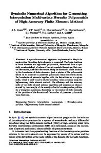
3 Proposed framework 3.1 Functional framework The proposed framework (Fig. 1) for the production of information that supports mass customization is based on automatically producing product production structure (PPS) for each product variation or customized item. Initially there has to be a means of creating the templates, which by virtue of being a template needs to be parametric. This constitutes the knowledge maintenance system (KMS). To
Int J Adv Manuf Technol (2008) 38:1244–1259
1249
Fig. 1 Functional framework
specify a customized product an interface is required and this interface is called a product configurator (PC). A product definition language (PDL) provides a method for communicating and storing this specification. The application that processes one or more PDL requests is called a PPS generator which output the PPS containing the BOM and assembly instructions. 3.2 Knowledge maintenance system (KMS) A standard CAD program assists with design of the base product. If customization is based on dimensions, the design will be parametric. In the implemented system at Gienow, a set of rules was included to specify the engineering constraints applicable to the building of the product. For example, if a customer requests a larger version of the product, additional components are added to the bill of materials (BOM) for reinforcement, or depending on options selected, the rules determine which parts are to be used in the BOM. These too may have parameters (parametric). After base products are designed, an assembly design is used to match the routing definition in the computer-aided product production specification (CA-PPS) module. This ensures that what was designed is going to be built. It also provides the framework for specifying what materials or parts are required to carry out operations. At the same time, the information required to deliver the material (input) and where to send the product (output) is specified. The information specification includes defining what information is required at each stage of the manufacturing process and what type of information is required (for example printed report, screen display, download to CNC machine, printed tag, and/or bar code identification). Together, these create the three types of templates (products, resources, and
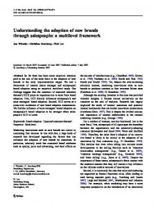
information) necessary to automate production of information for the OKP system. This function is called a knowledge maintenance system (KMS). 3.3 Knowledge characteristics A definition of the characteristics of a template is shown in Fig. 2. The figure demonstrates the characteristics using a wireframe diagram of the product. These characteristics also apply to three dimensional geometric designs as well. The expert system [37, 38] used at Gienow is a custom application and uses its own inference engine [39]. An expert system is made up of a set of production rules that applies to each product family and helps to determine how variations of products are made. The system stores information in relational databases (access and oracle), however, since the data has to represent the hierarchical nature of a bill-of-materials and operations, it has its own hierarchical structure built into the data structure. This structure is achieved by making use of the linked list [40] method and creating what is called a record list structure (RLS). The knowledge that makes up the data in the expert system comes from the product designers (i.e., the experts). To create the BOMs and work instructions for every variation of a product would require a lot of time and effort on the part of product designers on a daily basis. So the ‘knowledge’ about how to create the variation is captured in the expert system in the form of a set of rules. Then when a customer asks for a specific variation, the inference engine first selects the appropriate rules (which are contained in the template or model of the selected product), then ‘fires’ these rules in the correct sequence to produce the bill of materials and operations to make the custom product. The final stage of the inference is to apply
1250
Int J Adv Manuf Technol (2008) 38:1244–1259
Fig. 2 Wireframe diagram of a template
a set of constraints to enforce consistency in the output to ensure that the requested variation can be manufactured and will meet the specification of the product. The structure of knowledge is based on an object-oriented design [41] and so meta-classes act as the templates, classes are product variations, and objects are customized products. It makes use of inheritance and re-use of classes. It also has “intelligent components” which are similar to polymorphism. Intelligent components occur when a class automatically varies itself based on its location and application. These intelligent components can find the answers to the following questions: Where is the product production progress now? What are the connected or relevant parts and operations? What are the dimensions of the connecting parts? What operations are needed to make it? Knowledge consists of formulae, constraints (IF.... THEN....), queries or lookup references, macros or functions, objects with properties (length, width, color) and methods, variables and constants. Where possible, every unique piece of knowledge occurs once in the database and is used by reference. This facilitates ease of maintenance of the database so that only one value needs to be changed and its effect is propagated throughout the whole knowledge structure.
The kind of rules being used in the expert system can be demonstrated using an example where a customer requests a specific size. First, depending on the product and the configuration (a sub-set of variations), various component sizes are calculated by the parametric formula contained in the knowledge data. Constraint rules are used to tell the inference engine if the sizes of various components are within an acceptable range. If not, either the product cannot be made, or can be made but without warranty or can be made by adding some additional parts - reinforcing bar for example. Then the inference engine will add the necessary parts and operations to cut and assemble the additional parts. The object-oriented structure can be used for modeling a common component or sub-assembly. For example, all windows contain an insulated glass unit (IGU). The IGU is composed of two pieces of glass separated by a spacer bar and sealed so that air and water cannot get in between the two pieces of glass. When a customer selects a specific size, depending on the width, height, area and aspect ratio (width/height), glass with different thicknesses has to be used. Basically the larger the window is, the thicker the glass should be to maintain the structural strength of the product as it increases in size. Instead of repeating
Int J Adv Manuf Technol (2008) 38:1244–1259
knowledge about the making of an IGU in all the different product families and models, glass knowledge is contained in one model and the expert system defines a class which is used to create objects to be reused by any of the product families. This saves time in creating and maintaining the knowledge as product designs are constantly in change. In the case of the glass object, only one place needs to be changed, and this change is immediately available to all product families. 3.4 Product production structure (PPS) A customer specification interface is required so that customers can select a product and specify the parameters and options that go with it to make a customized item. This interface, called a product configurator, then creates a file containing this specification as a request to the PPS generator. The request format uses a special structure based on a product definition language (PDL). When the structure is based on XML, then the request is called a PDXML. The PPS generator then selects the product template, applies the parameters and options, and outputs the BOM and routings to the shop floor to have the product made. In the KMS it is useful to have a PDL viewer so that the knowledge engineer or worker can verify the creation or adjustment of template designs. This function would import a PDL request and interpret the relevant template, applying the parameters and options. It would then display a graphical view of the resulting product and produce a copy of the PPS.
4 Industrial implementation In order for these processes to be effective in enabling mass customization, the theory behind the framework introduced in this paper should have universal applications for one-ofa-kind production and mass customization. This claim is based on the following logic. For one-of-a-kind production (OKP) it is possible to produce custom design specification and manufacturing instructions using manual or conventional computer aids. For example a CAD application can output a bill-of-materials and assembly instructions. However, when a company starts to approach high volumes of one-of-a-kind products (i.e., mass customization) then the process of producing design and manufacturing information has to be automated to avoid chaos in production and to achieve high production efficiency. In order to achieve this computer aided process, knowledge about the design of the product and how it is made has to be captured in some kind of knowledge database. In order for the customers to specify their requirements, a user interface is required. From this specification information a basic product or
1251
template can be modified to produce information about the variant and how it has to be manufactured. 4.1 Gienow Windows and Doors Gienow Windows and Doors, a manufacturing company in Calgary, Alberta, Canada produces customized products for its customers. To enable their mass customization process they developed a system based on procedures as presented in this paper. The process used in Gienow is a combination of engineer-to-order and make-to-order. Prior to developing this system they were a make-to-stock with some make-toorder company. In developing their present production control system, they applied the basics of the theory and created a knowledge-based application called the knowledge maintenance system (KMS) along with a customer interface called AccuOrder. To communicate with customers and store the customers’ specifications they used a product definition language (PDL) based on a record list structure (RLS), the same as they used for modeling the knowledge. The application then processed PDLs against knowledge to produce the product production structure. PDLs were stored so that the PPSs could be regenerated any time. The information contained in the PPSs was then used to drive the rest of the production system. 4.2 Data structure As mentioned in the literature review, many methods for modeling production data have been developed in the past years [25]. In the window and door manufacturing industry, the concept of generic bill-of-materials and operations was originally implemented with the use of procedural scripts or programming languages. Gienow contemplated using one of these programs but determined that the programs would not be scalable to the size of company that Gienow envisioned they would become. Therefore, a method was necessary for storing similar information in a database with an interface that product design and process engineers could use without having to learn the scripting or programming language. In order to achieve this, a data structure was developed to contain the BOMs and operations for each product family. However, since these had to be generic in nature [26–28], i.e., containing all the information for all possible variations, it was necessary to include the rules for constructing the specific BOMs and operations for any possible variation. This is why an inference engine was required to process the rules and produce the product production structure (PPS) [30] for each custom product. Therefore, data structures for product templates and variation specifications are central to the framework of the system. Their roles are especially significant in a data drive
1252
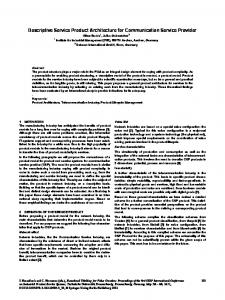
system as is the case for Gienow Windows and Doors. Their main database is called “Knowledge Database” as it contains knowledge about company products. The task to create and maintain the template database is called “data modeling”. Through data modeling, information about products, their components and the knowledge about how these components should be assembled to form a product, is defined. It includes such information as how sizes of components should be computed as well as how to compute cost of materials, cost of labor and labor times. The data to create variations comes from a user interface and has a structure of its own that, when combined with the required template, produces the specification of the product variation and its manufacturing instructions. In Gienow’s implementation a CAD application was not available at the time, so all of the design information was added manually to the knowledge database using wireframe diagrams. This design information was used to create models (templates) of the various products Gienow manufactured for its customers. Thereafter constraints were created and entered to add or remove parts and tasks as determined by product specifications. The knowledge database is a collection of rules and the program that processes these rules constitutes an inference engine. The inference engine currently in use at Gienow is constrained by the size of the database and the manner in which the rules are evaluated. The user interface generates variation requests using a product definition language (PDL) which is in the RLS format. This is sent to the knowledge database which in turn produces a product production structure (PPS) that contains all the information needed to manufacture the product. 4.3 Model or template data structure Model or template data structure is based on an AND/OR tree structure with built-in rules that determine how the tree should be constructed. Based on input information, a section of the database is selected and loaded into memory. The rest of the input information then determines the responses to a list of conditions and the corresponding actions to take. The end result is a tree structure that represents the bill of material of the product and the assembly process. Information contained in the data tree can then be produced in a number of formats, depending on the information model. Figure 3 shows a simple example at the final stage of a product assembly where the glass is added to the product frame and the glazing beads are inserted to keep the glass in the frame. The product family has two variations, a P and a PP, representing a single piece of glass or two pieces of glass. If the variation selected by the customer is a PP then the output BOM will contain P1 and P2 as well as two sets
Int J Adv Manuf Technol (2008) 38:1244–1259
Fig. 3 Template data structure with embedded rules
of four glazing beads (B1, B2, B3, and B4). The size of the product is also variable, therefore dimensions of the different components are functions of width (w) and height (h). In the case of the Gienow product families the number of variations becomes enormous. To ensure that results from the PPS generator are consistent and accurate, a baseline test of several hundred products is maintained. The baseline data set contains variations on all of the product families and includes variation that tests the constraints of each product, (for example the minimum and maximum sizes) when additional components like reinforcement are required and when materials have to be changed for structural reasons. All of the constraint rules are used in the client interface prior to the PPS generator running and therefore requests made on the generator are always valid. The inference engine [37] can handle complex situations where a number of product variations are combined to produce a compound product. Also the inference engine has a macro programming [42] feature which uses an iterative process so multi-level rules can be executed, allowing for complex products to be modeled. 4.4 Product definition language (PDL) The product definition language has seven basic elements: a product identification number (PIN), series or family, configuration (pre-defined variations or combinations), dimensions, data version, feature list, and PPS. All seven elements do not have to be present for a PDL to be valid. The creation and sometimes removal of each element is required at different stages of the product information definition cycle. Figure 4 gives a simple example of the format. 1. Product identification number (PIN). A PIN is a unique alpha numeric identification for the product. It may or may not have any coded meaning. It can be an
Int J Adv Manuf Technol (2008) 38:1244–1259
1253
6. Feature list. A configuration typically has many variable options. The user interface can help by supplying default values or selections based on a customer’s preference (learned or stated). There are two types of options. The first is a true option which is determined by an ON or OFF value. The second type of variable option is one that requires a value, such as color, to be specified. In this example the color may be “black” or “white” but it can not be “none”. These second types of options are features. –
–
Fig. 4 A product modeled by product definition language (PDL)
2.
3.
4.
5.
automatically generated sequential number, related to the order number and line number, or identify the product series or family, configuration, when it was made and some dimensions and/or options. Series or family. This places the PDL request into a context that will fully describe the product. It will identify a group of templates to be selected from the knowledge base. Configuration. The configuration describes the product in terms of a specific combination of pre-defined components. There can be many configurations in a series. Dimensions. Each configuration has a set of physical dimensions that must be specified to build it. For rectangular products this could be width and height. More dimensions need to be supplied for products with special shapes and different options. For some special shapes, the size may not directly be related to a physical dimension of a product but might instead be a geometric value such as radius or focal point. Data version. During the life cycle of the information, a data version may or may not be required. During quotation the system can use the latest version of the knowledge. For a replacement part for warranty or service, a data version will have to be specified. Prior to production, if the PPS does not have a data version the current version number that generated the PPS will be applied to the PDL.
Default option. Options are defined in the product knowledge database with default parameters for each option. In PDL, first parameter of an option is the default. Local option override. This knowledge includes global options for a product. For example, color could be set as a global option and then every component making up the product would be of the same color. However, if the color option is specified at a lower level (for one of the components) then the color specified for that option would override the global value.
7. Product production structure. After the inference engine is run for the PDL request, it returns a product production structure (PPS). This PPS is basically a very detailed product information tree that can be used as a source for shop floor instructions, production plans and management reports. The PPS structure is totally dependent on how the product is modeled in the knowledge database. Prior to the product being manufactured, a complete PPS is required. However, after the product is completed and shipped to the customer, the PDL can be archived without the PPS as it can be regenerated (based on the data version) by the inference engine if required at a later date. The example PPS shown in Table 1 is a representation of the output from the PPS generator when it uses the model or template shown in Fig. 3. In this example we can see that material and labor cost information are available in summary and detail. Information about the delivery of material and sub-components from work centers to work centers is also available. Assuming the process uses flexible manufacturing machines, computer numerically controlled (CNC), then information is available in the PPS to provide the instructions to these machines, whether that is in terms of lengths or areas to cut or perimeters to weld. With more detailed modeling these instructions can include drill and punch locations and milling instructions. By combining this information for a number of products, the work loads for various work centers can then be calculated. Production planning and resource allocation can
1254
Int J Adv Manuf Technol (2008) 38:1244–1259
Table 1 Example of product production structure (PPS) Product production structure Production identification (customer account code, order no., item no.) Item #
Description
Dimensions
Qty
Cost
Work Center
To Work Center
PP1
2-Lite Window
1
67.35
W15
SHIP
IGU IGU GB010 GB010 FPP1
Glass Unit Glass Unit Glazing Bead Glazing Bead Frame for PP1
1200 mm, 1200 mm 1200 mm, 600 mm 1200 mm, 600 mm 1200 mm 600 mm 1200 mm, 1200 mm
1 1 4 4 1
20.00 20.00 0.75 0.50 15.00
G1 G1 CUT CUT W14
W15 W15 W15 W15 W15
Task Id MIGU
Material Cost Description Make IGU
Time 300 secs
Qty 1
56.25 Cost 1.50
Work Center G1
Machine Id B001
MIGU
Make IGU
300 secs
1
1.50
G1
B001
CGB CGB INIGU INBG MFPP1
Cut Glazing Bead Cut Glazing Bead Insert IGU to frame Insert Glazing Bead Make Frame for PP1 Labor Cost
15 secs 15 secs 30 secs 30 secs 1200 secs
4 4 2 8 1
0.30 0.30 0.30 1.20 6.00 11.10
CUT CUT W15 W15 W14
SAW SAW
Instructions/Dimensions 1200 mm, 600 mm, Dual Glaze, 4 mm glass 1200 mm, 600 mm, Dual Glaze, 4 mm glass 1200 mm 600 mm
Welder
1200 mm,1200 mm
also be performed. Work schedules and synchronized delivery of material and sub-components can be achieved because each product and its PPS are uniquely identified and can be monitored and controlled one by one. This becomes the enabling factor for one-piece flow manufacturing. 4.5 Knowledge database All knowledge is contained in a database using a tree structure. A set of screen shots (Figs. 5, 6, 7, and 8) of the knowledge maintenance system (KMS) are given as follows to demonstrate how this system is used. When the KMS opens a knowledge-database it starts with a default tree view of the data. The main screen is divided into two views: the left hand side (LHS) view and the right-hand side (RHS) view. The default tree view is always in the LHS view, while all the knowledge views of the item selected in the tree view are shown in the RHS view. The main-view folder (Fig. 5) contains the overall structure that includes the products, conversion factors (meters to feet, etc.), data specifications (for downloads, cut sheet and other manufacturing reports), generic macros, global constants, global formulae (area of a circle, etc), material masters, material transports (definitions of carts and conveyers), reference tables and routings (shop floor layout and operations).
Fig. 5 Tree view - Main niew
Int J Adv Manuf Technol (2008) 38:1244–1259
1255
Fig. 6 Tree view - Models
The all-products folder contains product series or families. Within each series there can be a number of similar products. In the example shown in Fig. 5 there are industrial doors, industrial windows, patio doors, vinyl windows and wood windows, plus other ancillary products. The vinyl window folder is expanded and shows the content which is consistent for each product folder (Fig. 6). In it there are constraints, constructs, kits, labor, lookup tables, materials, and model. A product can have multiple templates in order to further define a “group of variations”. In Fig. 6, the tree view is further expanded to show the content of model (template) 185_S01. This is where the majority of knowledge about the product is contained Fig. 7 Tree view - Knowledge
(product structure, parts, operations, and data). It too forms a tree structure and is based on the variables contained in a PDL request. Figure 6 is the start of the ‘knowledge’ for a model of the 185 series window. The product family is divided into variation groups (or configurations) and the one shown is S01. The next part of the knowledge (in the screen shot) defines the wire frame of the product. It first defines the bounding shape, which in this case is a rectangle. The rectangle starts with a frame-head component and requires a starting point and end point in terms of x, y, and z coordinates. Then the right side of the rectangle is defined as a frame-jamb, also with start and ending points. Knowledge continues defining the geometry of all the major components
1256
Int J Adv Manuf Technol (2008) 38:1244–1259
Fig. 8 Tree view - Constraint
in the model. Figure 7 shows the same information in record format and can be edited. After this the constraints, in the form of rules, are added as shown in Fig. 8. Figure 8 shows the action of a constraint, when the sashjamb (which is the vertical side of the windows) is greater than 1000 mm. Then a second sash lock has to be added to the window and therefore to the bill-of-materials. For a window with a sash over 1000 mm in height, 2 sash locks are required to keep the window completely shut and sealed when closed. The custom product tree structure is built by resolving all the constraints. Constraints are rules with the structure of IF.... THEN.... If the constraint is satisfied then an action occurs. Actions are classified into 3 categories: to add a part, to remove a part, and to set a variable. Any number of these actions can be included. For example there could be three parts added, one part removed and two variables set. Macros or functions are used to determine the conditions or values of some knowledge. Formulae are used to calculate results when values of variables are given. The tree structure for a specific custom product is built and processed. This process is depicted in Fig. 9. The resulting product tree is then used to produce the PPS which contains all the information necessary to manufacture the product: bill-of-materials, routings (operations in various work centers) and data requirements. As mentioned in the definition of the framework, a function was added to the KMS to expand any specified PDL and show a graphical representation of the resulting product. This is demonstrated in Fig. 10. The model is first selected and then a PDL is imported. The KMS then processes the PDL request as described above and produces
the product tree. This is then represented in graphical form as shown in Fig. 10. Included with this function is a means of seeing the actual PPS for this product as well. 4.6 Implementation flowchart The following diagram (Fig. 11) represents the method that Gienow used to implement the functions of automatic generation of Product Production Structure (PPS). These were then imported into their enterprise resource planning (ERP) application.
Fig. 9 Tree structure process
Int J Adv Manuf Technol (2008) 38:1244–1259
1257
Fig. 10 Expanded PDL
5 Conclusions and future work 5.1 Successes and cost savings The successful implementation at Gienow Windows and Doors demonstrates the feasibility and effectiveness of this process for mass customization. The original method of making and supplying windows and doors to the construction industry was implemented by producing large quantities of standard sizes and selling from a warehouse with a Fig. 11 Implementation of computer-aided product production structure (CA-PPS)
lead time of 10 days. Lead times of 8 to 10 weeks were generally acceptable for custom products. As Gienow developed their fully customized production system, they were able to maintain competitive pricing while producing any product (standard or custom) in the same 10 day lead time. This effectively reduced their finished goods inventory to zero which significantly helped in keeping costs down. Since then, Gienow has enjoyed competitive advantages which have enabled them to grow from annual sales of $10M in 1990 to $120M in 2006. Today many
1258
other window and door companies have adopted the same manufacturing philosophy. With this method of manufacturing and through the use of information technology, Gienow has demonstrated that it is possible to mass customize at the same cost and with the same delivery times as mass producers in their industry. Gienow’s system produces 2000 PPSs per day, which are stored in the database for different lengths of time depending on the delivery and service of the products. This represents half a million products per year and this large amount of data will be stored for at least ten years so that Gienow can facilitate servicing of the customized product if and when required. This has further reduced the cost of servicing the product as it is not necessary to visit the building to take measurements of the products that require servicing or replacement. Cost savings in purchasing of raw materials and custom sub-components was also realized when using the data in the PPS to more accurately plan material requirements and ordering custom components accurately. The information also provides details of resource requirements so that scheduling and resource allocations can be performed more easily and accurately. Because each product is uniquely identified and accompanied by detailed information, the shop floor processes can be better managed and efficiency gains can be achieved. Overall the IT-enabled manufacturing system has made Gienow a very successful mass producer of customized windows and doors, and the company enjoys an international reputation for its innovation and quality of products. 5.2 System weaknesses and future work The implementation of this system in Gienow can be improved with the use of a parametric CAD application to create design information of the products in parametric form. This provides 3D information for the templates defined in terms of dimensions and parametric formulae. In the Gienow implementation, because integration with CAD application was not possible when the application was developed, the system only uses 2D line graphics, and dimensions and formulae have to be input by hand into the database. In Gienow’s implementation, routings were added to the BOM as tasks using the constraint function. Also, these constraint functions were added to the database manually. Implementation can be improved by developing a graphical interface that links the shop floor layout with the assembly structure of the BOM found in the design information. The data structure used in the Gienow system was based on a record list structure (RLS). The hierarchical structure is achieved by using pointers to owners and members. The application then reads this record structure to create data objects in memory and then processes the tree view using
Int J Adv Manuf Technol (2008) 38:1244–1259
the constraints to create the output tree structure. A modern object database could improve the performance of the application and this would be assisted by an improved classification method to identify commonly used data objects and store them more efficiently in memory. The PDL structure used to communicate the product specification would also benefit from a normalized structure in a relational database. Each PDL in the Gienow system contains a copy of all required information even if it is used in other PDLs or extracted from reference (look-up) tables. Even though Gienow implemented a re-use function for all formulae, the formulae are stored in the knowledge database using the same structure as all the other knowledge. Also the application has its own library of mathematical functions which it uses to perform calculations. These features lead to inefficiencies in calculation processes. The formulae should be contained in their own structure and the calculations should be performed using commonly available functions which have been optimized for performance. The PPS generator described in Sect. 4.2 initializes its memory by storing commonly used information from the knowledge database. This includes: global constants, formulae, macros, labor and lookup tables. Then it reads and stores the tree-view of the template in memory, uses the information in the PDL request to construct the formulae and constraints (rules), and then processes all the constraints while applying variables to create the output treeview of the BOM and routings. This approach can be replaced by compiling the knowledge database so that the basic functions of the application are already in machine code or interpretive form and the PDL request simply provides values for all the variables. In an implementation like Gienow where there is a large number of product families, each family could be compiled as a separate DLL which is initiated based on the product family specified in the PDL request. This would significantly increase the performance of the application and enable the production of PPS’s efficiently and in a timely manner. Acknowledgements The authors would like to acknowledge the support of Natural Sciences and Engineering Research Council (NSERC) of Canada through its Strategic Project grant, in collaboration with Gienow Windows and Doors Ltd. and Startec Ltd.
References 1. Davis S (1997) Future perfect. Perseus Books Group, New York 2. Pine BJ (1999). Mass customization: the new frontier in business competition. Harvard Business School Press, UK 3. Piller FT (2002) Customer interaction and digitization - a structured approach to mass customization. Moving into mass customization: Information systems and management principle, part II, pp 119–137, Springer, Berlin
Int J Adv Manuf Technol (2008) 38:1244–1259 4. Krajewski LJ, Ritzman LP (2002) Forecasting. Operations Management, Editors: Tucker T, Boardman PJ, Surich S, 6th edition, pp 539, Prentice Hall, New Jersey 5. Krajewski LJ, Ritzman LP (2002) Resource Planning. Operations Management, Editors: Tucker T, Boardman PJ, Surich S, 6th edn, pp 731–780, Prentice-Hall, Upper Saddle River, NJ 6. Jin G, Thomson V (2003) A new framework for MRP systems to be effective in engineered-to-order environments. Robot Comput Integr Manuf 19:533–541 7. Yan HS, Zhang XD, Ma XD (2002) Karmarkar’s and interaction/ prediction algorithms for hierarchical production planning for the highest business benefit. Comput Indust 49:141–155 8. Feiring B (1991) Production planning in stochastic demand environments. Mathl Comput Model 15(10):91–95 9. Vandaele N, de Boeck L (2003) Advanced resource planning. Robot Comput Integr Manuf 19:211–218 10. Kubat C, Taskin H, Topal B (2003) Comparison of OR and AI methods in discrete manufacturing using fuzzy logic. J Int Manuf 15:517–526 11. Ming XG, Mak KL, Yan JQ (1999) A hybrid intelligent inference model for computer aided process planning. Integr Manuf Systems 10(6):343–353 12. Kuo RJ, Wu P, Wnag CP (2002) An intelligent sales forecasting system through integration of artifical neural networks and fuzzy neural networks with fuzzy weight elimination. Neural Netw 15:909–925 13. Priore P, Fuente D, Pino R, Puente J (2003) Dynamic scheduling of flexible manufacturing systems using neural networks and inductive learning. Integr Manuf Syst 14(2):160–168 14. Jiao JX, Zhang YY (2005) Modeling of modularity and scaling for integration of customer in design of engineer-to-order products. Comput Aid Des 37(2):149–172 15. Shao XY, Wang ZH, Li PG, Feng CXJ (2006) Integrating data mining and rough set for customer group-based discovery of product configuration rules. Int J Prod Res 44(14):2789–2811 16. Svensson C, Barford A (2002) Limits and opportunities in mass customization for ‘build-to-order’ SME’s. Computers in Industry 49:77–89 17. Kotha S (1996) From mass production to mass customization: the case of the national industrial bicycle company of Japan. Eur Manage J 14:442–450 18. MacCarthy B, Brabazon PG, Bramham J (2003) Fundamental modes of operation for mass customization. Int J Prod Econ 85:289–304 19. Selladurai RS (2003) Mass customization in operations management: Oxymoron or Reality OMEGA. Int J of Manag Sc 32 20. Frutos JD, Borenstein D (2004) A framework to support customer-company interaction in mass customization environments. Comput Ind 54:115–135 21. Yao AN, Yang X, Rong Y (2007) Computer aided manufacturing planning for mass customization: part3, information modeling. Int J Adv Manuf Technol 32(1–2):218–228 22. Siddique Z, Ninan JA (2006) Product portfolio identification based on association rule mining. Integr Comput Aid Eng 13 (2):133–148
1259 23. Mukhopadhyay SK, Setoputro R (2005) Optimal return policy and modular design for build-to-order products. J Oper Manage 23 (5):496–506 24. Guangming Z, Yujin H, Xuelin W, Chenggang L (2004) The representation of conceptual product based on component-connector design feature with P/T net approach. Int J Adv Manuf Technol 26:1193–1201 25. Rolstadas A (1991) ESPRIT basic research action No. 3143 - FOF production theory. Comput Ind 16:129–139 26. Hegge HMH, Wortmann JC (1991) Generic bill-of-material: A new product model. Int J of Prod Econ 23:17–128 27. Du X, Jiao J, Tseng M (2002) Graph grammar based product family modeling. Concurrent Eng: Res Appl 10(2):113–128 28. Huang GQ, Zhang XY, Liang L (2005) Towards integrated optimal configuration of platform products, manufacturing processes, and supply chains. J of Ops Manag 23:267–290 29. Tu YL, Chu XL, Yang WY (2000) Computer aided process planning in virtual one-of-a-kind production. Comput Ind 41:99–110 30. Tu YL, Xie SQ (2001) An information modeling framework to support sheet metal parts intelligent concurrent design and manufacturing. Int J of Adv Manuf Technol 18:873–883 31. Tu YL (2002) Automatic scheduling and control of a ship web welding assembly line. Comput Ind 29(3):159–171 32. Jinsong Z, Qifu W, Li W, Yifang Z (2004) Configuration-oriented product modeling management for made-to-order manufacturing enterprises. Int J Adv Manuf Technol 25:41–52 33. Li B, Chen L, Huang Z, Zhong Y (2005) Product configuration optimization using a multi-objective genetic algorithm. Int J Adv Manuf Technol 30:20–29 34. Zeng FS, Jin Y (2006) Study on product configuration based on product model. Int J Adv Manuf Technology 33:766–771 35. Matta A, Semeraro Q (2005) A framework for long term capacity decisions in AMSS. Design of advanced manufacturing systems. Springer, Berlin 36. Luger GF (2002) Expert system technology. Artificial Intelligence, 4th edn. Addison-Wesley, Harlow, England, pp 249–250 37. Fujimoto H, Ahmed A (2003) Assembly process design for managing manufacturing complexities because of product varieties. Int J Flex Manuf Syst 15:283–307 38. Padhy NP (2005) Expert systems. Artificial intelligence and intelligent systems. Oxford University Press, India, Ch 6:278–335 39. Padhy NP (2005) Fuzzy systems. Artificial intelligence and intelligent systems. Oxford University Press, India, Ch 7:336–399 40. Weiss MA (1999) Linked list. In: Hartman S, Harutunian K, Unubun P (eds), Data structures & algorithm analysis in Java. Addison Wesley Longman, Reading, MA, pp 56–57 41. Booch G (1990) In: Apt A, Telatnik MA (eds) Object oriented design with applications. Benjamin/Cummingsy, San Francisco, CA 42. Scott ML (2000) Recursion and Macros. In: Penrose EM, Wade M (eds), Programming language pragmatics, 6.6. Academic, San Diego, CA, pp 297–303