Sep 19, 2012 - Because of this, technology transfer takes decades. ...... the ISO 12207 [ISO08]. ...... processes, i.e., in web portals such as IEEE Xplore. ...... meets our idea of providing process patterns so that the user is free to configure.
Masterthesis
A Framework for Goal-oriented Process Configuration Context-Specific Configuration of SE processes in SPEM
Philipp Diebold 9/19/2012
Department of Computer Science University of Kaiserslautern
in Cooperation with
Fraunhofer Institute for Experimental Software Engineering First Examiner: Prof. Dr. Dr. h.c. Dieter Rombach Second Examiner: Dr.-Ing. Andreas Jedlitschka (IESE)
Statement of Authorship:
Except where reference is made in the text of “A framework for goal-oriented process configuration”, this contains no material published elsewhere or extracted in whole or in part from a thesis presented by me for another degree or masters. No other person’s work has been used without due acknowledgement in the main text. This thesis has not been submitted for the award of any other degree or masters in any other tertiary institution. Bretzenheim,
(Philipp Diebold)
September 19, 2012
Acknowledgements
This master thesis and the research presented would have never been possible without the support and understanding of my family and friends. I was very lucky to have friends and colleagues who supported me in different ways in these exhausting months and during my whole study. In the first place, I thank Dr. Andreas Jedlitschka from the Fraunhofer IESE for being the supervisor of this thesis and for supporting me during the research and writing period. He offered me the opportunity to do this thesis within the context of the ARAMiS project which is partly handled by the Fraunhofer IESE and the Software Engineering Research Group: Processes and Measurement. It was very interesting and stirring to work in a big project together with industrial partners. I would also like to thank Dr. Jens Heidrich from the Fraunhofer IESE and Dr. Christiane Plociennik from the Software Engineering Research Group of the University of Kaiserslautern. Jens Heidrich was my first contact person at the IESE and he offered me some possible thesis topics and then referred my supervisor, Andreas Jedlitschka. In addition Christiane Plociennik was a big help for me, because she is the person responsible for the ARAMiS Project from the Software Engineering Research Group of the University. She also supported me in some tasks, e.g., selection of technologies provided by the industry partners, by offering me help from her research assistant(s). Special thanks go to all the friends and my family who directly supported me and my research work. Some of my fellow students assisted me as a kind of counterpart for discussing ideas and implementations. Especially I want to give thanks to Kevin Krüger, Thilo Rauch and Nena and Eric Egli for reviewing and proof-reading of the written report.
Executive Summary
This research for this thesis was conducted to develop a framework which supports the automatic configuration of project-specific software development processes by selecting and combining different technologies: the Process Configuration Framework. The research draws attention to the problem that while the research community develops new technologies, the industrial companies continue only using their well-known ones. Because of this, technology transfer takes decades. In addition, there is the fact that there is no solution which solves all problems in a software development project. This leads to a number of technologies which need to be combined for one project. The framework developed and explained in this research mainly addresses those problems by building a bridge between research and industry as well as by supporting software companies during the selection of the most appropriate technologies combined in a software process. The technology transformation gap is filled by a repository of (new) technologies which are used as a foundation of the Process Configuration Framework. The process is configured by providing SPEM process pattern for each technology, so that the companies can build their process by plugging into each other. The technologies of the repository were specified in a schema including a technology model, context model, and an impact model. With context and impact it is possible to provide information about a technology, for example, its benefits to quality, cost or schedule. The offering of the process pattern as output of the Process Configuration Framework is performed in several stages:
I Technology Ranking:
II Technology Combination:
III Process Configuration:
1 2 3 4 5 6 7 8 9 10
Ranking based on Application Domain, Project & Impact Ranking based on Environment Ranking based on Static Context Creation of all possible Technology Chains Restriction of the Technology Chains Ranking based on Static and Dynamic Context Extension of the Chains by Quality Assurance Process Component Diagram Extension of the Process Component Diagram Instantiation of the Components by Technologies of the Technology Chain 11 Providing process patterns 12 Creation of the process based on Patterns
The effectiveness and quality of the Process Configuration Framework have additionally been evaluated in a case study. Here, the Technology Chains manually created by experts were compared to the chains automatically created by the framework after it was configured by those experts. This comparison depicted that the framework results are similar and therefore can be used as a recommendation. We conclude from our research that support during the configuration of a process for software projects is important especially for non-experts. This support is provided by the Process Configuration Framework developed in this research. In addition our research has shown that this framework offers a possibility to speed up the technology transformation gap between the research community and industrial companies.
Zusammenfassung
Diese Forschungsarbeit wurde durchgeführt um ein Framework zu entwickeln, welches automatische einen Projekt-spezifischen Software Entwicklungsprozesses durch das Auswählen und Kombinieren verschiedener Technologien bereitstellt: das Process Configuration Framework. Das adressierte Problem in der Forschung ist dabei, dass in der Forschung neue Technologien entwickelt werden, diese die Industrie jedoch nicht verwendet. Daraus ergibt sich, dass der Transfer von Technologien meist Jahrzehnte dauert. Zusätzlich ist es der Fall, dass es keine Einheitslösung für ein Software Projekt gibt. Dies bedeutet, dass für ein Project mehrere Technologien kombiniert werden müssen. Das in dieser Arbeit entwickelte und erläuterte Framework behandelt ein Großteil dieser Probleme, durch eine engere Verknüpfung von Industrie und Forschung sowie das Unterstützen von Software Unternehmen bei der Auswahl der passenden Technologien für den Software Entwicklungsprozess. Dabei wird die fehlende Technologie Transformation durch das Technologie Archiv ersetzt, welches im Process Configuration Framework verwendet wird. Der Prozess wird durch die SPEM Prozess Pattern konfiguriert, welche für jede Technologie einzeln bereitgestellt werden. Damit ist es den Unternehmen möglich den Prozess individuell zu erstellen. Die Technologien wurden in einem speziellen Schema erstellt, welches das Technologie-, Kontext sowie das Einfluss-Modell beinhaltet. Durch den Kontext und den Einfluss ist es möglich Informationen der Technologien bereitzustellen, wie zum Beispiel Vorteile der Qualität, Kosten oder Zeit. Das Bereitstellen der Prozess Pattern als Ergebnis des Process Configuration Frameworks wird in mehreren Stufen durchgeführt:
I Technology Bewertung:
II Technology Kombination:
III Prozess Konfiguration:
1 2 3 4 5 6 7 8 9 10
Bewerten von Anwendungsdomäne, Projekt & Einfluss Bewerten von Umgebung Bewerten von Statischem Kontext Erstellung aller möglichen Technologieketten Einschränkung der Technologieketten Bewerten von Statischem und Dynamischem Kontext Erweiterung der Ketten um Qualitätssicherung Prozess Komponenten Diagramm Erweiterung des Prozess Komponenten Diagramm Instanziierung der Komponenten durch Technologien der Technologiekette 11 Bereitstellen der Prozess Pattern 12 Erstellung des Prozesses basierend auf den Pattern
Zusätzlich zu der Entwicklung des Process Configuration Framework wurde die Effektivität und Qualität durch einen Fallstudie evaluiert. Dabei wurden von Experten manuell erstellte Technologieketten mit den automatisch erstellten Ketten des Frameworks mit den Konfigurationen der Experten verglichen. Dieser Vergleich zeigte, dass die Ergebnisse des Frameworks ähnlich waren und somit ein guter Vorschlag sind. Die Folgerung aus der Forschungsarbeit war die Wichtigkeit der Unterstützung der Prozesskonfiguration von Software Projekten, im speziellen für Nichtfachleute. Diese Unterstützung wird durch das in dieser Arbeit entwickelte Framework bereitgestellt. Außerdem wurde gezeigt, dass das Framework die Möglichkeit bietet die Technologietransformation zwischen Industrie und Forschung zu beschleunigen.
Table of Contents
1
Introduction ................................................................................................................................... 1 1.1
Research Approach.................................................................................................................. 2
1.2
Outline of the Thesis ............................................................................................................... 4
Part I: INTRODUCTION INTO RESEARCH .................................................................................. 5 2
Background .................................................................................................................................... 7 2.1
Decision Theory and Decision-Making................................................................................... 7
2.2
Software Processes .................................................................................................................. 9
2.2.1
Life-cycle- / SE Phases.................................................................................................... 9
2.2.2
Process Meta-Model ...................................................................................................... 11
2.3 3
Related Work ............................................................................................................................... 15 3.1
Method Platform – A literature review.................................................................................. 15
3.1.1
Background – Method Platform .................................................................................... 15
3.1.2
Review Method ............................................................................................................. 16
3.1.3
Results ........................................................................................................................... 19
3.1.4
Conclusions ................................................................................................................... 21
3.2 4
Technology Categorization Schemas in Software Engineering ............................................ 14
Process Configuration / Creation........................................................................................... 22
Problem Description.................................................................................................................... 23 4.1
Defining the Problem ............................................................................................................ 23
4.2
Approaching the Solution ...................................................................................................... 24
4.3
Research Goals ...................................................................................................................... 26
Part II: RESOLUTION ...................................................................................................................... 27 5
Technology Categorization ......................................................................................................... 29 5.1
5.1.1
Technology Model......................................................................................................... 30
5.1.2
Context Model ............................................................................................................... 32
5.1.3
Impact Model ................................................................................................................ 33
5.2 6
Categorization Model ............................................................................................................ 29
Input Model ........................................................................................................................... 35
Technology Ranking.................................................................................................................... 37 6.1
Ranking Process .................................................................................................................... 37
6.2
Ranking Value ....................................................................................................................... 38
6.2.1
Context Attributes ......................................................................................................... 38
6.2.2
Impact Attributes ........................................................................................................... 43
6.3
Chapter Summary .................................................................................................................. 45 i
A Framework for Goal-oriented Process Configuration 7
Technology Combination ............................................................................................................ 47 7.1
Combination Process ............................................................................................................. 47
7.2
Creation of all Technology Chains ........................................................................................ 48
7.2.1 7.3
Technology Chain Restriction ............................................................................................... 49
7.3.1
Preset Technologies ....................................................................................................... 49
7.3.2
Interdependencies .......................................................................................................... 50
7.3.3
Existing SE Objects ....................................................................................................... 50
7.3.4
Results of Restriction Step ............................................................................................ 51
7.4
Technology Chain Ranking ................................................................................................... 51
7.4.1
Static Context ................................................................................................................ 52
7.4.2
Dynamic Context ........................................................................................................... 56
7.4.3
Results of Ranking Step ................................................................................................ 57
7.5
Technology Chain Extension by Quality Assurance ............................................................. 57
7.5.1 7.6 8
Results of Chaining Step ............................................................................................... 49
Results of Technology Chain Extension Step ............................................................... 58
Chapter Summary .................................................................................................................. 58
Process Configuration in SPEM................................................................................................. 59 8.1
General Configuration Process .............................................................................................. 59
8.2
Process Component Diagram ................................................................................................ 60
8.3
Process Component Diagram Extension ............................................................................... 60
8.4
Instantiation of the Process Components by Technologies ................................................... 61
8.5
Creation of the Process Patterns ............................................................................................ 62
8.6
Chapter Summary .................................................................................................................. 65
Part III: APPLICATION & EVALUATION ................................................................................... 67 9
Process Configuration Framework ............................................................................................ 69 9.1
Prerequisites .......................................................................................................................... 69
9.2
Phase-based Approach .......................................................................................................... 70
9.3
Dynamic Approach................................................................................................................ 72
10 Evaluation .................................................................................................................................... 75
ii
10.1
Hypothesis ............................................................................................................................. 75
10.2
Design.................................................................................................................................... 76
10.2.1
Unit of Analysis............................................................................................................. 77
10.2.2
Context .......................................................................................................................... 78
10.2.3
Case: Scenario – Software Project ................................................................................ 79
10.3
Results ................................................................................................................................... 79
10.4
Discussion ............................................................................................................................. 81
10.4.1
Hypothesis ..................................................................................................................... 81
10.4.2
Further Findings ............................................................................................................ 84
10.4.3
Threats to Validity ......................................................................................................... 86
10.4.4
Conclusion ..................................................................................................................... 87
11 Conclusion and Future Work ..................................................................................................... 89 11.1
Conclusion on the Research Problem and Questions ............................................................ 89
11.2
Contributions ......................................................................................................................... 90
11.3
Limitations............................................................................................................................. 91
11.4
Future Work .......................................................................................................................... 91
11.5
Concluding Remarks ............................................................................................................. 93
References ............................................................................................................................................ 95 Appendix A – Literature Review ..................................................................................................... 101 Appendix B – XML Technology Template ..................................................................................... 105 B.1 Technology Model .................................................................................................................... 106 B.2 Context Model .......................................................................................................................... 109 B.3 Impact Model ............................................................................................................................ 111 Appendix C – Technical Realization Aspects ................................................................................. 115 Appendix D – Evaluation .................................................................................................................. 117 D.1 Scenario .................................................................................................................................... 117 D.2 Configuration Templates .......................................................................................................... 118 D.3 Raw Data .................................................................................................................................. 119
iii
A Framework for Goal-oriented Process Configuration
Table of Figures
Figure 1. Workflow of the Research ....................................................................................................... 2 Figure 2. Workflow of Part I: Introduction into the Research................................................................. 5 Figure 3. Structure of SPEM 2.0 Meta-Model [OMG08] ..................................................................... 12 Figure 4. Key terminology of SPEM mapped to Method Content versus Process [OMG08]............... 13 Figure 5. Evolvement of Technology Categorization Schemas ............................................................ 14 Figure 6. Stages of the paper selection process ..................................................................................... 17 Figure 7. Method Platform trend over time ........................................................................................... 20 Figure 8. Graphical Representation of a Method Platform ................................................................... 21 Figure 9. Detailed Workflow of the Research ....................................................................................... 25 Figure 10. Workflow of Part II: Resolution .......................................................................................... 27 Figure 11. Relation of the three models ................................................................................................ 30 Figure 12. Result of the Chaining Step ................................................................................................. 49 Figure 13. Result of the Restriction Step............................................................................................... 51 Figure 14. Result of the Ranking Step................................................................................................... 57 Figure 15. Result of the Technology Chain Extension Step.................................................................. 58 Figure 16. Generic Process Component Diagram ................................................................................. 60 Figure 17. Transformation Extensions of the PCD ............................................................................... 61 Figure 18. Verification Extensions of the PCD ..................................................................................... 61 Figure 19. Process Component Instantiation ......................................................................................... 62 Figure 20. Process pattern Creation....................................................................................................... 64 Figure 21. Process Configuration by using process patterns ................................................................. 65 Figure 22. Workflow of Part III: Application & Evaluation ................................................................. 67 Figure 23. Static Process Configuration Framework ............................................................................ 70 Figure 24. Dynamic Process Configuration Framework ....................................................................... 72 Figure 25. Evaluation Design ................................................................................................................ 77 Figure 26. Process Configuration Framework in Use ........................................................................... 92 Figure 27. XSL Schema of the technology model (starting at the Technology attribute) ................... 106 Figure 28. XSL Schema of the technology model (starting at the Description attribute) ................... 107 Figure 29. XSL Schema of the technology model (starting at the Static Context attribute) ............... 108 Figure 30. XSL Schema of the context model (starting at the Context attribute) ............................... 109 Figure 31. XSL Schema of the context model (starting at the Environment attribute) ....................... 110 Figure 32. XSL Schema of the impact model (starting at the Impact attribute) .................................. 111 Figure 33. XSL Schema of the impact model (starting at the OnDevelopmentCosts attribute) .......... 112 Figure 34. XSL Schema of the impact model (starting at the OnDevelopmentSchedule attribute) .... 113 Figure 35. Process Configuration Framework Architecture ................................................................ 115
iv
Table of Tables
Table 1. Different life-cycle phase classifications ................................................................................ 10 Table 2. Data extraction form................................................................................................................ 19 Table 3. Model for Technology based on [Jed09] ................................................................................. 30 Table 4. Model for Context based on [Jed09] ....................................................................................... 32 Table 5. Model for Impact based on [Jed09] ......................................................................................... 33 Table 6. Model for Input (based on Table 3, Table 4 and Table 5) ....................................................... 35 Table 7. Initial configuration for the Technology Ranking ................................................................... 36 Table 8. Similarity of the Experience .................................................................................................... 43 Table 9. Similarity of the ISO 9126 (Sub-) Characteristics .................................................................. 44 Table 10. Initial configuration for the Technology Chain Ranking ...................................................... 52 Table 11. Similarity values of the different Requirement formats ........................................................ 54 Table 12. Technology Chains manually created by the Experts ........................................................... 79 Table 13. Different Configurations of the Process Configuration Framework ..................................... 80 Table 14. Technology Chains automatically configured using different configurations ...................... 80 Table 15. Position of the three manually selected chains in the different configurations ..................... 81 Table 16. Technology Chain Similarity ................................................................................................ 82 Table 17. Number of Papers in the different stages in the databases .................................................. 101 Table 18. Number of Papers sorted by publication year ..................................................................... 101 Table 19. Number of Papers sorted by conferences- and journal topics ............................................. 102 Table 20. Number of Papers sorted by domains .................................................................................. 102 Table 21. Number of Papers sorted by input, output and decision-making ........................................ 103 Table 22. Software Project Scenario for the Evaluation ..................................................................... 117 Table 23. PCF Configuration Template 1 ........................................................................................... 118 Table 24. PCF Configuration Template 2 ........................................................................................... 118 Table 25. List of all 27 Technology Chains ........................................................................................ 119 Table 26. All 27 Technology Chains ranked based on the different configurations ........................... 120
v
A Framework for Goal-oriented Process Configuration
Table of Rules
Rule 1. Rule for Technology Ranking based on Industrial Sector & Project Size ............................... 39 Rule 2. Rule for Technology Ranking based on Project Kind, Development Process & Paradigm .... 40 Rule 3. Rule for Technology Ranking based on IT- & Development environment............................... 40 Rule 4. Rule for Technology Ranking based on Training..................................................................... 41 Rule 5. Rule for Technology Ranking based on Qualification & Experience ...................................... 42 Rule 6. Rule for Technology Ranking based on ISO 9126 ................................................................... 43 Rule 7. Rule for Technology Ranking based on Development Costs & - Schedule .............................. 44 Rule 8. Rule for Technology Chain Restriction based on Preset Technologies.................................... 49 Rule 9. Rule for Technology Chain Restriction based on Interdependent Technologies ...................... 50 Rule 10. Rule for Technology Chain Restriction based on Existing SE Objects .................................. 50 Rule 11. Rule for Technology Chain Ranking based on I/O-Interface Matching ................................. 53 Rule 12. Rule for Technology Chain Ranking based on Complementary Technologies ...................... 55 Rule 13. Rule for Technology Chain Ranking based on Paradigm & Development Process .............. 56
vi
Introduction
1
Introduction
The domain of software engineering has advanced rapidly over the last decades. Today, software is a part of almost every other industry, such as automotive, telecommunication or health care [Bir97]. To address requirements of the different domains and individual organizations, a large number of different methods, techniques and tools (technologies) (e.g., [KB09]) evolved. Some address the whole development process, for example, Requirements-Based Engineering, whereas others address a tiny aspect during the development, such as a safety analysis method. Each technology1 is assumed to have a specific impact on either product quality, development costs, or project schedule. In many domains, aspects of product quality, such as safety, are becoming important key performance indicators along with project costs and schedule [Jed09]. Typically, models such as the CMMI [CKS11] do not explicitly define which technologies have to be applied. Further complicating the situation, “there is no one-size-fits all”, or as S. Fraser wrote in [FM08], there is no silver bullet available in software engineering. This implies that it is almost impossible to find a technology that supports all needed elements of individual software projects. Thus the combination of appropriate technologies to be used for a project is a challenging task. Some technologies are a better fit for specific projects than others. This leads to the problem of finding the most appropriate technologies for the specific projects. This choice is very difficult because of different selection criteria, e.g., context and different needs of the stakeholders. Some criteria focus on quality aspects and others try to optimize the costs or schedule. All these aspects have to be considered when configuring a “best-fit” development process. This complex task of selecting the technologies for configuring the development process is often applied by experts (or a group of experts in the Software Engineering Group). In addition to this dependence on experts, there is the problem of making new technologies availability to industry. This is because typically, “technology transfer takes on the order of 15 to 20 years to mature a technology to the point that it can be popularized and disseminated to the technical community at large” [RR85]. Also most often new technologies are directly borrowed from friendly or rival companies [JCF07]. To solve these problems, we propose a means to support the selection of well-suited (research) technologies and configuring a context-specific process: the framework for goal-oriented process configuration. Our research focuses on process patterns and combines the most appropriate technologies for a specific project context in order to configure the most appropriate process. This solution should not replace the expert. Rather it should provide non-experts a guideline for the technology selection and process creation.
1
Technology definition of [BCR01a]
1
A Framework for Goal-oriented Process Configuration
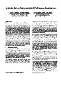
1.1 Research Approach During the work for this research, several research methods such as literature review and experiments were applied. The next figure (cf. Figure 1) summarizes these different steps and gives an overview of the flow of the research work. It contains six major steps.
Figure 1. Workflow of the Research
In Part I: Introduction into the research: In step one, we investigate the exact problem by using different research approaches. We conduct a systematic literature review in order to find more details about the domain and problem. These findings about the state-of-the-art research led to a precise picture of the domain and how similar problems were solved.
2
Introduction In Part II: Resolution: The second step deals with the categorization of the technologies. We adapted the categorization schema of [Jed09] with regard to our findings of step one. This adaption includes only those attributes and elements that were required to change the schema for needs of the following steps. In doing this, we assume that technologies are described and stored according to the characterization scheme evolved from step two. In step three, we select the Technology Chain best fitting to the specific project. In particular, we develop the concept for the ranking of the technologies with regard to their appropriateness based on specific inputs for context and impact. Therefore, we conceptualized a prioritization mechanism for the different attributes, based on rules. Further, we present how we combine the ranked technologies to Technology Chains by specifying combination parameters. The combination is done for the entire software life-cycle, by considering whether a technology fits to prior phases and to the users input. Step four, the last step of the resolution, is about the process configuration. Based on the outcome of this step, we specify context-specific and optimal process patterns for each software project. This will be realized with a general modeling method, the Software & Systems Process Engineering Metamodel Specification [OMG08]. In Part III: Application & Evaluation: Part three contains two additional research steps, which combine the approaches of part two and also deals with an evaluation of the Process Configuration Framework. The fifth step contains the explanation of the overall Process Configuration Framework. In particular, we explain the phase-based (and dynamic) approach of the framework by using the approaches presented in part two. Step six presents the evaluation of the Process Configuration Framework. We conducted a case study with experts from Fraunhofer IESE2. Due to their roles they are involved in industry projects thus having relevant experience.
2
Fraunhofer Institute for Experimental Software Engineering, Kaiserslautern
3
A Framework for Goal-oriented Process Configuration
1.2 Outline of the Thesis This research workflow is presented in three different parts:
Part I
Introduction into research
This part introduces the research. Chapter 2
Provides an overview of the research background.
Chapter 3
Describes the state-of-the-art by a discussion about the related work.
Chapter 4
Gives a detailed description of the problem which will be solved and analyzed in the other two parts.
Part II
Resolution
This part describes the different steps of the technology ranking and combination right up to the process configuration. Chapter 5
Provides a description of the technology schema based on [Jed09] and specifies its use for this specific research.
Chapter 6
Describes the ranking of the most appropriate technologies based on context and impact input of the software company.
Chapter 7
Describes the concatenation of technologies of the different life cycle phases and combines them to a Technology Chain.
Chapter 8
Specifies the Technology Chain of Chapter 7 as process patterns, based on the process meta-modeling language SPEM [OMG08].
Part III
Application & Evaluation
The last part describes the application of the developed framework in Part II and their evaluation. Chapter 9
Builds the two different Process Configuration Framework approaches based on the stages of Part II.
Chapter 10
Evaluates the developed framework by performing a case study.
Chapter 11
Summarizes the contributions and describes the limitations and lessons learned.
4
Part I: INTRODUCTION INTO RESEARCH
Part I: INTRODUCTION INTO RESEARCH
The main objective of this thesis is to provide a Process Configuration Framework. This framework configures a context-specific software development process in SPEM by using a number of most appropriate technologies. This research is located at the intersection of software processes and decision-making, in particular, technology selection and combination. The portion of the thesis introduces the research areas.
Figure 2. Workflow of Part I: Introduction into the Research
The “Background” chapter (cf. Chapter 2) deals with the background knowledge of decision theories, the software development life-cycle as well as software processes. The decision theory is needed for the selection of the technologies (cf. Section 2.1) as it is for the combination of the technologies of the different life-cycle phases (cf. Section 2.2.1). Software processes are needed for the last stage of the framework, which should transfer the best technologies of the chain to process patterns. One outcome of this chapter refers to the theory of decision-making process. The section on software processes yields knowledge about processes and their modeling. The last background section deals with existing categorization schemas of technologies, how they evolve and the one used in our research. The chapter “Related Work” (cf. Chapter 3) is about the state-of-the-art in this research area. The topic of this thesis arises from the German research project ARAMiS [KIT11], which includes a section about a continuous development method, more precisely a method platform (German: “Methodenplattform”). Therefore, this chapter includes a systematic literature review of this topic.
5
A Framework for Goal-oriented Process Configuration The final chapter, “Problem Description“ (cf. Chapter 4), defines the problem addressed in this thesis. This is accomplished by drawing conclusions from the findings of the previous two chapters which are based on different literature research methods.
6
Background
2
Background
The purpose of this chapter is to describe the background of our research. This simplifies the understanding of the context in which this thesis takes place. The main findings of this chapter are:
Understanding of the background regarding decision theory and software processes Explanation of the life-cycle phases for a software development project Explanation of SPEM and the concepts of this language used in this thesis Introduction of different technology categorization schemas and their evolution
The first section starts with a brief overview of the topic of decision-theory (cf. Section 2.1). This is necessary to get a better understanding for later decisions about technology ranking and combination. Those will be treated in PART II: RESOLUTION, especially Chapter 6 and 7. The second section starts with a brief overview of software processes which will be followed by a detailed description of the software development life-cycle. This is very important for the combination of the technologies in a later chapter (cf. Chapter 7). The last subsection deals with aspects of process modeling, where we focus on a Meta modeling language called SPEM. For later needs the last section contains information about the existing technology categorization schemas. Within this section the most important schemas are briefly introduced. In addition to this, the evolution and merging of the schemas over time is depicted. The latest and one of the biggest schemas of Jedlitschka [Jed09] is then particularized in Chapter 5 because it is the one used in our research.
2.1 Decision Theory and Decision-Making The task of decision making and the decision theory are everyday tasks, because everyone needs to decide between different possibilities in daily life. These decisions are mainly solving everyday problems by doing the thing, which seems to be the right one. These kinds of decisions in a more formal way are also used in research in many different domains, not only software engineering. Applying different approaches, such as the experience factory [BCR01a] combined with the Quality Improvement Paradigm (QIP) [BCR01b], is important in software engineering. The decision making incorporates those approaches because the experience factory provides a holistic approach for learning from existing (software project) knowledge. Those can be reused for the decisions of the subsequent projects. Decision support should be applied throughout the entire life-cycle of the software development, as explained by [Ruh03]: “For the requirements, analysis, design, construction, testing and evolution phases, decision makers need support to […] rank, select or reject candidate products, processes or tools.” There are several approaches for performing the decision making, regardless of the life-cycle phase. The most used approaches in decision theory will be introduced in the next paragraphs.
7
A Framework for Goal-oriented Process Configuration One of the most common decision-making approaches deals with fuzzy logic [Ros10]. This theory started in 1965 with [Zah65] and is based on many-valued and probabilistic logic. In contrast with traditional logic, which has only true or false values, fuzzy logic variables have a truth value between 0 and 1. This means it deals with a kind of partial truth. The representation of such values is mainly based on different functions. For example the meanings of cold, warm and hot are represented by functions mapping a temperature scale. Each point of the scale has a number of “truth values”, where each of those values is representing one function. In contrast to the approaches based on fuzzy logic there are some approaches using probabilistic decision theory. This theory is based on probability (e.g., of experts or combined with knowledge base) or different technologies working with probability, such as probabilistic networks. Example approaches which are often used are stochastic petri nets [Mar89]. In addition there are also other probabilistic approaches, e.g., probabilistic decision trees [KM86]. The third theory type has already been mentioned as extension of the probabilistic ones, knowledgebased decision theory [Doy02]. Approaches working with this type of theory, need some kind of knowledge, such as context data of different projects or other data, e.g., from the experience factory [BCR01a]. The usage of data-driven approaches is a chance and weakness together because it is difficult to get (and access) the data. But with this data from some experience base the decisions are more precise. “Data-driven decision making must not cause us to lose sight of the larger context, what I call knowledge-based decision making.” [Doy02] In addition to the three decision theories mentioned, there are several other theories in the literature. These other theories are generally interconnected and often a combination of several theories. There are different approaches for implementing decision theory. The rule-based systems [Hay85] are based on top of the above mentioned theories. This is the case because within this approach, rules need to specify how the decision takes place. In these rules different decision theories can be used (e.g., rules for implementing fuzzy logic decisions). All of the rule-based approaches are structured in a very similar way. They first contain a condition part describing what needs to be fulfilled for applying the rules (similar to the IF-part in programming languages). Second, they include an action part describing the action when the condition is fulfilled (similar to the THEN-part in programming languages). In addition to the rule-based approaches there exists also similar ones dealing e.g., with decision tables. The rule-based systems have been mentioned in this chapter because this is the implementation of the decision system we are using in this thesis. The decision theory mainly used in this research is based on existing knowledge as it will be explained later. For developing and implementing the rule we use Drools Expert [JBo12], the rule engine of Drools – a business logic integration platform.
8
Background
2.2 Software Processes In the domain of software engineering, processes assume a major role because quality aspects and project goals are more and more influenced by using project specific processes. Processes are defined in several different ways, and some of these definitions will be covered in the next paragraphs. Most of the different software (development) process definitions deal with the context. Other similarities are the transformation of input products into outputs, possible refinements with sub-processes as well as performance by humans, machines or both together [Hei11]. An abstract definition of a process is given by [Ost87]: “While a process is a vehicle for doing a job, a process description is a specification of how the job is to be done. Thus cookbook recipes are process descriptions while the carrying out of the recipes are processes.” This definition is especially effective because it is based on a familiar activity. In [FH93] a process is defined as “a set of partially ordered steps intended to reach goal” which is a generic definition, not only software engineering specific. There are many possible definitions, but this one best fits this research project as it includes steps and goal orientation. In [Lon93] a software process model is defined as “An abstract software process description. It can be more or less formal.” This definition is an improvement of the process definition of [FH93], which also deals with the process description as a specification. Such software process models use different notations (e.g., graphical or textual [natural language, machine readable]) and different abstraction levels (e.g., livecycle level, engineering process level or atomic step level). In general we use the highest abstraction level in this research, the life-cycle level. But the static approach (cf. Section 9.2) as well as the more dynamic approach (cf. Section 9.3) can also be used in lower levels, e.g., inside one SE phase. In addition to this level we introduce a standardized general modeling notation used for processes, SPEM [OMG08]. The next two sections cover the aspects of the software life-cycle phases and the SPEM modeling notation. First in the subsection about life-cycle phases (cf. Section 2.2.1) the different phases of a software project will be explained. Then Section 2.2.2 contains the details of the Software & Systems Process Engineering Meta-Model published by OMG in 2008 [OMG08]. 2.2.1 Life-cycle- / SE Phases The different life-cycle phases of a software project are a major part of the logical separation of different project activities. Each of the SE phases concludes in the completion of a document / SE object and the achievement of a milestone. A general software development project contains several different life-cycle phases, which can be referred to different names in literature. Two very important software engineering books of Summerville [Sum07] and Jalote [Jal08] specify SE phases in a similar way. For example Jalote in [Jal08] provides the following four phases: Requirements Analysis, Software Design, Coding and Testing Summerville [Sum07] uses similar phases: Software Specification, Software Design & Implementation, Software Validation and Software Evolution
9
A Framework for Goal-oriented Process Configuration In addition to phase definitions provided by important software engineers there are also standards, e.g., the ISO 12207 [ISO08]. This international standard provides five different activities around the software life-cycle, whereas the most important for us are the development activities. This activity includes seven steps which can be aggregated to the definition of life-cycle phases we are using in this thesis: Specification/Requirements, Architecture, Design, Implementation, Verification & Validation The comparison of Table 1 between the different phases of [ISO08], [Sum07] and [Jal08] shows, that some of the provided phase classifications are more detailed than others. Therefore, we tried to use a classification taking all needed aspects into account. Although some of the literature classifications combine them to one phase, Table 1 shows that the first five phases of our classification are consistent with the other ones. Only the verification phase is new. This is needed for assuring that all aspects of quality assurance [Rak01] can be covered by the schema, because validation only covers the testing aspects.
Table 1. Different life-cycle phase classifications
Summerville [Sum07]
Jalote [Jal08]
ISO 12207 [ISO08]
Diebold
Specification
Requirements Analysis
Design & Implementation
Design
Specification Architecture Design Implementation
Validation
Testing
Evolution
-
Requirements High level Design Module Design Coding Module-, Integration- & System testing -
Coding
Validation Verification -
The starting phase is the Specification. This phase does not necessarily need input to start, because it is the initial phase, and often the problem description is elaborated with the customer at this time. The output of this phase is a specification document often called the requirements specification document. It includes all the functionality of the software and constraints about it. This phase can be subdivided into two major aspects, the problem understanding and then documenting the requirements. The next phase, called Architecture, is not directly specified in the other classifications. In [Jal08] and [Sum07] the architecture is included in the Design phase. In contrast, [ISO08] specifies it as High level design because it focuses on divide and conquer and the high-level interaction. This phase works on planning a solution for the problem based on the requirements document. The output of this step is an architecture document/model, which is usually a set of diagrams (e.g. UML diagram). This phase is the step from the problem domain into the solution domain [RII05]. Within this phase the software system is divided into subsystems and components to get a better understanding of the structure of the system. The focus of this is on the interaction between the different components to behave as a single system. In contrast to the architecture phase, the Design phase deals with lower level concepts. The design is sometimes called detailed or module design (e.g., [ISO08]). As the architecture covers the aspect of what modules are needed, the design specifies how the modules can be implemented. The focus of this phase is on designing the logic of the individual modules. The inputs of this phase are the architecture document as well as (optionally) the specification. The output consists of the design document/model, which contains the detailed description of each module to simplify the implementation in the next phase. 10
Background After completing the design, the Implementation takes place. Because the previous phases contain the major decisions, the main implementation task is the translation of the architecture and design into source code. During this translation, programming language specific details need to be decided. Implementation has a big influence on the following phases because of its strong interconnection with the code. After the completion of the code, the integration of the different modules into one single system is also part of this phase. The Testing phase, also called Validation, is one of the two quality assurance phases. The goal of this phase is the detection of software defects in the code. This is done in different levels of abstraction. On the lowest level there is module testing where the different components are tested individually. Afterwards they are integrated, which is validated by using integration testing. The last testing part is the system testing. This tests the system against the system requirements that were developed during the specification phase. The acceptance testing works similar to the system testing but it is performed in the real environment. The outputs of this phase are the test cases including test data. Some software companies document the test cases which are implemented in the testing phases during specification. Verification is the second quality assurance phase. It is the only one with connection to most of the other phases, because it verifies the output against the output of the previous phases, e.g., the requirements document against the problem description. Therefore, in this phase all inputs are possible. Verification should detect uncovered aspects, errors, etc. of the actual document. This is done for example with inspection techniques [GG94]. 2.2.2 Process Meta-Model Today there exist several different process models. All these different models use various notations and specifications. Therefore, the Object Management Group (OMG)3 developed a specification which is a standard for modeling processes, called Software & Systems Process Engineering Meta-Model (SPEM) [OMG08]. Because the developed framework will have process patterns as an output, we want to model this output with a standard. We use the SPEM notation and explain it in the following paragraphs. In general, meta-modeling is the construction of rules, constraints, models and theories applicable and useful for modeling classes of problems. A meta-model is a model one abstraction layer higher than the original model, which gives the possibility of defining models. The definition of such meta-models is derived from the MetaObjectFacility (MOF) [OMG11] by the OMG. SPEM was first developed by the OMG in version 1.0 in 2002 and then refined in 2008 [OMG08]. It is a meta-model based on MOF. Because it supports concepts for modeling, documenting, presenting, exchanging and executing of methods and processes, we chose this model. The structure of SPEM is depicted in Figure 3, where the different packages were interconnected with a merge-relationship.
3
Consortium for modeling and developing model-based standards
11
A Framework for Goal-oriented Process Configuration
Figure 3. Structure of SPEM 2.0 Meta-Model [OMG08]
Figure 3 shows the basic package on the bottom, the Core. It contains the basic classes and abstractions for all other packages of the meta-model. The ProcessStructure is built upon the Core and contains the basic classes for defining process structures. The ProcessBehaviour is an extension of the ProcessStructure by using the MethodContent. The goal of this package is enhancement by defining execution semantics. This package also gives the possibility of extending elements with external behavioral models. The ProcessWithMethods merges the same packages as the ProcessBehavior but with the focus on method elements. This package enables the possibility of modeling processes as method element instances. The elements of the MethodContent serve as the definition point, which can be instantiated in processes. The package ManagedContent gives the possibility of combining textual descriptions with process element. An extension of the ManagedContent is the MethodContent, which enables the possibility of defining basic elements for modeling methods (e.g. roles, work products and tasks). The last package is the MethodPlugin. By merging the ProcessStructure, ProcessWithMethods and MethodContent, this package uses all possibilities of SPEM. It enables the concepts of method libraries and processes, which increase reuse. The reuse aspect works mainly by using same elements of the method content for several processes. During this instantiation an adaption of the elements is possible. The later parts of the framework using SPEM are based on the MethodPlugin.
12
Background
Figure 4. Key terminology of SPEM mapped to Method Content versus Process [OMG08]
Inside the SPEM specification there is the differentiation of static (method content) and dynamic content (processes) as shown in Figure 4. This is derived from the Rational Unified Process (RUP) [EM03]. The Method Content elements are used for defining elements and describing what, how and who. Examples are Roles, Work Products and Tasks. Processes are more focused on the project flow. They instantiate elements of the method content for defining processes. Each usage of an element creates a new instance (Task-, Role- and Work Products Use). Figure 4 gives an overview of all the different elements of SPEM and their affiliation. Not all the different elements of Figure 4 are explained in this thesis. Only the concepts used in this thesis will be introduced when they are needed, further information can be found in [OMG08]. Using all the possible elements, SPEM supports different kinds of modeling processes. Most important to our work are the process patterns and their refinements explained in [OMG08]. They will be used in Chapter 8 because the outcomes of the framework are those process patterns.
13
A Framework for Goal-oriented Process Configuration
2.3 Technology Categorization Schemas in Software Engineering The software domain has a wide range of technologies and schemas which results from the different phases of the development life-cycle (cf. Section 2.2.1). One example is the categorization schema for selecting software testing techniques [Veg02], but there are also many reasons for the numerous different categorization schemas. For the framework we are developing in this thesis, a general technology categorization schema is needed because the approach covers technologies from all different life-cycle phases. Therefore, some of the existing schemas are irrelevant for our work, although they will be briefly used in the next paragraph to show the evolution of such schemas. In literature we find a huge number of existing schemas, which overlap or have merged over time to become complete. Figure 5 provides an overview of the most important categorization schemas over time. The figure also contains the relationship between them:
Figure 5. Evolvement of Technology Categorization Schemas
The beginning of technology schema development (Figure 5, left) started in the late 80’s by Basili and Rombach [BR88]. This was then refined twice. The first time was in 1991 [BR91] and the second revision, in 1994, was called the experience factory approach. ([BCR94] is the edition which preceded [BCR01a]). Simultaneously to the experience factory approach of Basili, Rombach and Caldiera, the Software Engineering Institute (SEI) published the C4 Software Technology Reference Guide (SEI C4 TRG) [SEI97], which provides a catalogue of around 60 technologies. Both starting points result into two different lines. The line started by the experience factory results in several publications (e.g. [Hen96], [JAD01]). The work of the SEI was not used much. The first important publication using the SEI C4 TRG was [Bir] by Birk. This publication was the first to merge both lines into one schema. Afterwards, more publications appeared using Birk’s work as a starting point. [Veg02] and [Din02] use it for their research. The newest schema is [Jed09] by Jedlitschka developed in 2009 (Figure 5, right). This is a refinement and also generalization of the approach of Birk. However, this schema also incorporates publications of Jedlitschka: [JAD01] and [JHS05]. Because [Jed09] is the result of all the evolution of the different schemas we will use and adapt this schema for our needs. This adaption is explained in Chapter 5.
14
Related Work
3
Related Work
This chapter provides state-of-the-art overview of the domain we are working in and where the research takes place. The main purposes of this chapter are:
Understanding of method platform and similar frameworks Comparison between different method platforms and their realization Description of existing Process Creation or Process Configuration approaches
The first section contains a systematic literature review regarding method platform and similar frameworks. This is done in the formal and systematic way of [Kit04], and all the results of this will be presented in this section. The remaining section deals with the process creation and process configuration. Within this, we want to discuss existing approaches for creating and configuring software processes. Because most of the publications in literature are about business process creation, this section is rather short.
3.1 Method Platform – A literature review Platforms can be considered a collection of similar things. Such platforms were used in almost every domain for clustering special things. This is especially true in the software domain, in which methods, technologies, and tools were clustered in a separate platform. To get an overview of existing method platforms and equivalent frameworks, we reviewed the existing literature to gather existing knowledge about such frameworks. In this thesis we are also developing such a framework/platform. The following systematic literature review was performed similar to the procedure of [Kit04]. 3.1.1 Background – Method Platform Before defining the objectives of this review, we need to define a method platform in order to determine which frameworks belong to it or similar to it, and which do not belong to it. For method platforms there are no definitions given in the literature, which means we cannot refer to one given definition but have to define it ourselves. As mentioned in the beginning of this section, a platform is collection of things, similar to a repository or knowledge base. In this case, the platform contains methods and technologies, which are sometimes seen as the same thing. In this research we take the technology definition given by [BCR01a]. Therefore, the platform must contain technologies. In addition to this kind of repository, such platforms have an input as well as an output. Most often a single technology or a selection of technologies is the output of such method platforms. The selection of this output is mainly done based on the input and some decision-making in between. For such platforms there is no unique and general input similar to the technology as output. In addition to the input and output, some kind of decision-making is necessary to belong to the domain of method platforms. There are several ways to decide which of the technologies in the platform are best suited to the input. Some examples for decision making have already been introduced in Section 2.1.
15
A Framework for Goal-oriented Process Configuration One purpose of this research is the characterization of a method platform seen from different literature sources in the domain of computer science, particularly in software engineering. The other purpose of this systematic review is the comparison of existing method platforms. This comparison is done by using different aspects, e.g., the domain, input, decision-making and output. For this reason, the objective of this literature review is to answer the following research questions: 1. What is currently known about method platforms and their benefits and limitations? 2. What are these platforms used for? 3. In what way do they differ and what impact does this difference have for the method platform? What are the advantages and disadvantages of the different method platforms? 3.1.2 Review Method Informed by the established method of systematic reviews [Kit04], we separate the review in different stages:
research questions inclusion criteria exclusion criteria search strategy quality criteria data extraction
Because the research questions had already been defined in the previous subsection, we then dealt with the different inclusion and exclusion criteria. Papers were eligible for inclusion in this review if they presented something about a method platform or similar frameworks. This was checked by using the definition of Section 3.1.1. The various search terms were specified in order to determine whether a publication included a method platform. Those can be found three paragraphs below. It was also necessary for the papers to pass the minimum threshold defined by the quality criteria in a later paragraph. This systematic review only included papers published after year 2000. This was because method platforms and similar frameworks were not available before that time, which we discovered during the first search of different databases. As additional inclusion we considered publicatiosn only in English because most of the literature in the searched databases is in English. Publications in German and other languages do not consider this topic in the software domain. Studies were excluded if their (main) focus has nothing to do with a method platform or a similar framework. It was sometimes difficult to get the main focus and it was possible that some inappropriate papers were chosen. Furthermore, all papers that did not belong to the domain of computer science were excluded. There were several papers which also belonged to another domain (e.g. electronics) because of the strong interconnection of the different domains. These papers were included because they contain information about method platforms used in computer science as well as the application domain.
16
Related Work The search strategy included several electronic databases which included the conferences and journals which are the most relevant for this topic. During the first stage of selection we found the most important papers based on the number of publications. These following electronic databases were searched:
ACM Digital Library IEEE Xplore ScienceDirect – Elsevier SpringerLink
Figure 6 shows the systematic review process and the number of papers identified at each stage. In Stage 1, all the metadata and abstracts of the publication in the included electronic databases were searched using the following search terms: (1) (2) (3) (4) (5)
"method platform" "technology selection" "technology selection framework" "technology decision framework" "process selection framework"
Figure 6. Stages of the paper selection process
All these search terms for articles which belong to the topic of method platforms were combined using the Boolean “OR”. This means the article needed to include only one. This results in the search term of: 1 OR 2 OR 3 OR 4 OR 5 This paragraph contains information about the citation management, retrieval and inclusion decisions used during the stages of the selection process. Relevant citations from Stage 1 (n = 1439) were entered and stored in Mendeley4. This was done to get an overview of all the relevant papers and to record the source of each citation. A similar categorization was done for the other subsequent steps of the paper selection process. All data of relevant papers from the different stages of the process were saved in specific files and were presented in the Appendix A.
4
Software for managing and sharing research papers, discovering research data and collaborating
17
A Framework for Goal-oriented Process Configuration At Stage 2 (n = 150) we went through all the titles of the papers that resulted from Stage 1, to determine their relevance regarding method platforms. At this stage, papers that were clearly not about method platforms or similar frameworks were excluded. For example, because our search strategy included the term “technology … platform”, we got several results dealing with different kinds of technology platforms. Papers with titles that indicate clearly that the papers were outside the scope of the systematic review were excluded. Sometime the titles are no clear indicators of the papers topic. In such cases we included the papers for reviewing in the next stage because it could not be decided whether they fit the scope or not. At the end of this second stage only 150 papers were included, which means almost 90% of the papers of the first stage were excluded because of their title. At Stage 3 (n = 54), papers were excluded if their main focus had nothing to do with method platform or selection framework. This was indicated by means of the paper’s abstract. During this stage, we found abstracts of variable quality. Some of the abstracts were missing, poor and/or misleading. If the topic was unclear from the title, abstract, and keywords, the papers were included for a detailed quality assessment in the last step. After Stage 3, the 54 remaining papers were assessed according to five criteria. The following criteria are adaptations and selections of those given in [Pyr99] and [TF84]. The adaptation and selection of only a part of these criteria was needed because they have a huge range. We only used some general parts and specific questions about instruments, which was in our case the platform. Those five criteria cover the main quality issues that needed to be considered when validating the different publications identified during the review. The quality assessment issue was the trustworthiness of the data and information about the method platforms presented in the papers. We included several criteria that were related to the quality of describing method platforms or similar frameworks, their aims and contexts. Therefore, each study was assessed according to whether: 1. The title of the paper was sufficiently specified. 2. The researcher began by specifying the problem area. Was the importance of the specific problem domain shown? 3. There was a detailed description of the methodology or at least another source where additional information could be obtained. 4. There was some kind of explanation about the input, the decision-making and the output of the method platform. (Similar to the definition of Section 3.1.1) 5. There was some evidence (e.g. for temporal stability, content validity, empirical validity) given about this approach. Was an Experiment, Case Study or something similar performed?
18
Related Work Table 2. Data extraction form
Paper / Publication Description 1. Paper identifier Unique id for the specific paper 2. Date of data extraction 3. Publication Year 4. Publication Type Journal article / conference paper 5. Publication Source Which journal / conference? 6. Publication Title Method Platform(or similar framework) 1. Name 2. Input 3. Decision-making method What theory is the base for the decision? (e.g., fuzzy logic, , expert-based, … see Section 2.1) 4. Output 5. Description Or reference of the description 6. Used in Application domain 7. Used for Purpose of the method platform Reported Results 1. Benefits 2. Drawback 3. Evidence e.g., authors assumption, lessons learned, observed effect in laboratory/practice, confirmed hypothesis, ...
During quality assessment, we extracted the data from each of the 23 papers remaining after Stage 4. The data was included in this systematic review according to a predefined extraction sheet (cf. Table 2). This form made it possible to record the full details of each paper and to specify how each of them addressed our research questions. Some papers did not provide all the data we tried to record in Table 2. For this reason the data table in the appendix (cf. Appendix A) has some empty attributes. The publication description, data about the method platform (e.g. name, input, output, etc.) and the reported results by the authors of the publications were noted in a qualitative and descriptive analysis using MS Excel5. In contrast to similar systematic literature reviews, we did not perform a synthesis of the findings because the purpose of this review was scoping of the domain of method platforms. We provided an overview of different platforms in this domain. These findings are presented in the next subchapter using mainly descriptive analysis technique [Tro06]. 3.1.3 Results We finally identified 23 papers on the topic of method platform or similar frameworks. Most of the selected papers did not contain the term method platform but a related term, e.g., selection or decision framework. The number of resulting papers was about 2% of the papers after the first stage (n = 1439) of selecting publications from the electronic databases by using specific search terms. The specific data for the different stages was also separated for the different databases and can be found in Appendix A. As already mentioned in the review method section, namely in the inclusion and exclusion part, we considered only papers which belonged to the computer science domain. Thus this does not mean that there were papers which used parts of computer science for the method platform but generally belonged to another domain.
5
Spreadsheet application for calculating and different kinds of analysis
19
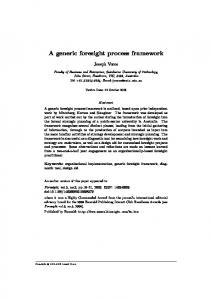
A Framework for Goal-oriented Process Configuration The analysis of the domains of the different approaches specified in the publications resulted in eight different domains. These domains were computer science (9), manufacturing (3), economics (2), ecology (2), electrical engineering (2), health care (2), human resources (1) and telecommunication (1). The most common domain was the computer science domain with almost 39% of the publications. Within those nine papers some were general papers, others are from bioinformatics. The majority belonged to software engineering. In these six publications, main parts of the software engineering life-cycle were covered, e.g., testing (3), verification & validation (1) and architecture (1). Because the papers arose from different domains, they were published in wide range of conferences and journals, which are also in different domains. Only a small number of them were mentioned more than once: Conferences on Empirical Software Engineering (2), Power Engineering (2), Communication (2), Management of Engineering & Technology (2) and Journals on Information & Technology (3), Systems (3). The year of publication was also relevant for this analysis because the topic could be outdated. We started the analysis of method platforms in 2000 because there was no appearance in the literature before that date. The trend over the years is shown in Figure 7. It shows the published papers regarding the discussed topic from 2000 until today. Although there were not that many publications, over the last decade the number of papers has increased (cf. Figure 7, trend marked as dashed line).
5
number of papers
4
3
2
1
0 2000 2001 2002 2003 2004 2005 2006 2007 2008 2009 2010 2011 year Figure 7. Method Platform trend over time
More important than the analysis of the occurrence of method platforms over time are the attributes of method platforms and how they are satisfied. These are the input, output and the decision-making in between, which is derived from the definition given above. The definition of method platforms given above starts with the input for such frameworks. This input can be of any kind. The different kinds of inputs collected from the publications are technologies (7), context (6), problem or goal (5), defects, database, boundary conditions, user preferences and requirements (each 1). It is obvious from the number of indications, that there are three main input possibilities: (a set of) technologies, the context or the problem/goal. Those possibilities can be classified in two categories. One has a set of technologies as input and selects the most appropriate output. The other group uses context, goal or problem as an input for selecting the best output. In this case there exists already a set of technologies where the selection takes place. 20
Related Work The next part of such a platform is the decision-making process, which is the most important step. This is the case because in this part the decision takes place based on the input. It needs to be decided which of the technologies is the most appropriate and will be provided as output. This is easier with using the second category of input because the platform can select the optimal technology quite directly from the specific context, problem or goal which is given. The other category instead gives a set of technologies but no direct hint how to select the optimal one. In this case it is more difficult to decide because there is no input simplifying the decision. In addition there were different decisionmaking approaches used in the publications: fuzzy logic (7), rule-based (3), probability-based (2), TOPSIS6 [SSL07] and other approaches which can be seen in Appendix A. Most of the frameworks use fuzzy logics, e.g., fuzzy sets, fuzzy AHP7 or fuzzy TOPSIS [BR06]. The second and third most often used approaches are rule- or probability based approaches. We also assume that most of the method platforms use some kind of rule-based approach on top which is not explicitly specified in the publications. Approaches using probability values appear also in some frameworks. The probabilitybased ones work with some kind of prediction, which is based on the probabilities, context and knowledge from previous input-output-combinations. The specification of the output of such method platform in literature contains no different outputs. This is the case because almost half of the 23 resulting papers directly use a technology as output and the others something similar which is related to technologies, e.g., combination of technologies or ranked technology list. 3.1.4 Conclusions The method platforms and similar frameworks presented above are spread over a wide range of (sub) domains and almost a decade of time. They give a good overview regarding what is important for such platforms and how this can be realized. As given in the definition in the background section, they need an input, a decision-making process mainly using the input, and an output (cf. Figure 8). The input can be a set of technologies or some kind of context, problem or goal description. The processing of the input takes place in the decision-making process, which is responsible for selecting the output. For the realization of this part there are different approaches and they were introduced briefly in Section 2.1 about decision theory. The output is a technology or something related to this.
Figure 8. Graphical Representation of a Method Platform
6 7
Technique for Order Preference by Similarity to Ideal Solution Analytic Hierarchy Process
21
A Framework for Goal-oriented Process Configuration
3.2 Process Configuration / Creation The term process configuration which was also part of the title of this thesis could be misleading in the software domain, because it was often used for business processes [GWJ91], [AHW03], [Aal11], etc. This was not the focus we were looking for because we are interested in the configuration of the software development process. In the software engineering domain two different aspects of processes were considered. First the overall development process described the process procedure, e.g., waterfall, iterative, prototyping. The second aspect was the process itself which described the methods used in the different life-cycle phases and how they are related. This was independent from the development process because it was needed no matter which one is chosen. This was the reason because a software development had a predefined ordering already introduced in Section 2.2. For the further part of this thesis we were only interested in the second aspect, the first one was covered by the Technology Categorization (cf. Chapter 5). In this thesis process configuration was chosen as a term, because it should cover the process creation in an automatic way. This aspect was rarely covered in the software domain because the companies only used a limited set of technologies in their process and used the overall development process. The decision which technology takes place manually based on their favorite technologies and experience. There were only a very small number of approaches that try to cover the same problem. For example in [CKO92] the authors focus on a process-driven software development environment. Their paper describes an approach of modeling the input representations used for development of process by transforming it into an output representation for process engineering.
22
Problem Description
4
Problem Description
The purpose of this chapter is to describe and define the problem, which will be solved in this research. The approach for solving its solution will also be described shortly. The main findings of this chapter are:
Providing a detailed description of the problem we are working Describes an overview of how the solution to the problem is discovered Give a brief description of the research goals
In the first section a detailed description of the problem is given based on the problems identified in the previous chapters. This is done by capturing the findings and problem of the background and related work section and merging them together into one problem. Besides this some questions out of the literature are also addressed belonging to the definition of the problem. Therefore, they are also provided with the solution in this thesis. The second section gives a brief overview of how the specified problem of the previous section can be addressed. Therefore, this section describes the research approach for getting the solution to the problem. The last section briefly introduced the research goals based on the previous problem description and the evaluation of the framework.
4.1
Defining the Problem
As already introduced in Chapter 1, the issue of creating the most appropriate process for a software development project before the start, arises due to the following circumstances:
Technologies are not applicable to the same extent in different projects with different context and impact. And there is no one-size fitting solution for each project available. [FM08] Software companies do not invest that much time and money in the software process. Technologies delivered from research often lack relevance and the transfer “takes on the order of 15 to 20 years to mature a technology to the point that it can be popularized and disseminated to the technical community at large” [RR85]. Often companies only introduce “new technologies directly just from friendly or rival companies” [JCF07] . Combining technologies is a complex task because of different technology specifications and also the quality of the combination of the different technologies.
From the literature review (cf. Section 3.1) of existing method platforms or similar frameworks we concluded that there is a need of a framework including a method platform which is based on some technologies and their empirical data. Those empirical data consists of the context the technology has been applied in and the impact the respective technology has in the context. That information is addressed in different technology categorization schemas from which one will be used in the Section 5.1. But the decision-making part of platforms with a general schema is currently not addressed. 23
A Framework for Goal-oriented Process Configuration From the analysis of existing process configurations or -creations approaches we came up with the knowledge that processes creation is more important in the business area then in the software domain. This is the reason why there are no approaches describing an automatic or semi-automatic approach for configuring a process. Furthermore there is no approach trying to build the software process specific for the different projects and their needs. Concluding from the analysis of the state-of-the-art, there is no approach (in the literature) available that addresses afore mentioned issues. Summarizing the previous sections, the state-of-the-art with regard to method platforms and semi-automatic process configuring can be summarized as follows:
Few generic technology schemas are available that provide some good support for selection and combination. Different selection strategies are available but most of them are only used in very specific domains. Process configuration/creation is more important for business processes than for the software development process. Combining technologies of a generic schema for modeling a process is not addressed in the literature.
During this research, we will also address some aspects and questions revealed in existing literature. For example a part of our research is the selection of most appropriate technologies with respect to the context which is relevant for [MRB82] and [Tet90]. This addressed aspect is also taken part of our research because it is needed as a step of the solution approach. We could not integrate their solution in our work because of the usage of a more generic technology model.
4.2 Approaching the Solution To solve the issues identified in the previous sections, this research provides a framework that helps software companies configuring their process for specific software projects. This framework should deal as an interconnection between research and industry. Today’s problem is that “Technology transfer takes on the order of 15 to 20 years to mature a technology to the point that it can be popularized and disseminated to the technical community at large” [RR85]. In addition to this problem the framework integrate new technologies faster and not only technologies “directly from friends or rival companies” [JCF07]. This framework uses all (also new) technologies and provides the best combination of technologies for the specific project to the software company. The solution partially originates from ideas of the ARAMiS project8 [KIT11]. We enhance these ideas (e.g. the modeling with SPEM) by extending a method and process platform to an automatic way of configuring the software process for specific projects. This is the case because we wanted to provide a more generic result which can also be used in other projects. Different research methods have been applied in the course of this research, e.g., literature survey and a case study. Figure 9 summarizes the flow of the research work which will be briefly introduced in the next paragraphs. In Step 1, we introduce the research. First the background of this work is discussed which is needed to get the understanding for the following steps. To further explore the problem within the state-of-theart we conducted a literature review. Finally the problem is defined.
8
The author of this thesis was partially involved in the ARAMiS-project [KIT11] at the Fraunhofer IESE and the Software Engineering Research Group of the University of Kaiserslautern.
24
Problem Description In Step 2, the technology categorization schema of [Jed09] is introduced, refined and adapted to the specific need of this research. In addition to the adapted work of [Jed09] there is also an Input model specified. If the information of Chapter 5 is not enough the Appendix B provides XML schemas for most of the models used during this thesis.
Figure 9. Detailed Workflow of the Research
The next two chapters together build the technology configuration step (Step 3). In this section the technology ranking is the first step by assigning a value to the different technologies based on their matching to the respective project context. Afterwards the technology combination uses the ranked technologies and combines them to all possible Technology Chains. This combination is independent of the project context. It uses the information of the different technologies and the ranking values calculated before. At the end of this step the outcome is the Technology Chain with the highest value. In Step 4, the process configuration, the output of the technology configuration is used. It transforms the technologies of the chain to process patterns. Those patterns are presented in the SPEM notation which we already introduced in Section 2.2.2. Then it is easy to configure the overall development process by using the patterns.
25
A Framework for Goal-oriented Process Configuration The first step of Part III develops the two possible approaches for the Process Configuration Framework by cascading the approaches of the previous steps. The phase-based as well as the dynamic approach are explained. Although the static one using the SE phases is more important, because the other one is briefly mentioned and moved to future work. The last step was conducted to evaluate the Process Configuration Framework of Step 5, which is the fusion of the Steps 2 - 4 (cf. Part II: RESOLUTION). We planned and conducted a case study with experts to verify our research goals and questions.
4.3 Research Goals Because the problem was already described in a subchapter this section will focus on the research goals. Those are strongly interconnected with the evaluation in Chapter 10. The generic research goal is the conceptual development of the Process Configuration Framework to solve most of the problems described in the previous chapters. With this framework we intent to simplify the development of software projects by providing a process at the beginning of the work. For the evaluation, we formulate the following hypothesis: The Process Configuration Framework provides process patterns for modeling a process which is comparable good as a process of an expert. Comparable good has two different meaning. First it could mean that the chains using the same technologies. Second it could mean that they are similar in their Technology Chain value as well as in the top chains, e.g. the Top 5. The resulting configuration is among the alternatives the expert would consider.
26
Part II: RESOLUTION
Part II: RESOLUTION
In Part I: INTRODUCTION INTO RESEARCH, we provided the underlying concepts and the background which is necessary to understand the following research. Also the state-of-the-art of method platforms was presented by means of a literature review (cf. Section 3.1). The last chapter of the first part specified the research problem. The purpose of Part II of this thesis is the resolution of the specified research problem. This is done by (1) developing a technology categorization model, (2) specifying how technologies are ranked based on input model , (3) combining the most appropriate technologies from the previous step to find the most appropriate Technology Chain and last (4) configuring a process based on this chain. This Technology Chain is specified in more detail with process pattern based on SPEM [OMG08]. Figure 10 shows the workflow for this resolution part.
Figure 10. Workflow of Part II: Resolution
In order to work with a general schema, no matter which life-cycle phases the technology is applied in, we first describe and adapt the schema of [Jed09]. Section 5.1 gives a detailed description of the schema, which was briefly mentioned already as part of Section 2.3. This section contains only the needed parts for the following sections and explains their importance.
27
A Framework for Goal-oriented Process Configuration In Chapter 6 we describe how technologies are ranked based on a given user input. This technology ranking is based on different approaches, which had been introduced in the background chapter. We use a specific ranking system for sorting the different technology based on the matching of the context and the impact. After knowing the quality of the matching attributes the ranking value for each technology is specified using rules. Using these ranked technologies, we combine the technologies of the different life-cycle phases in Chapter 7. This is one part within a step-by-step approach. First we build all possible Technology Chains. After this we restrict those chains, so that the number of possible chains decreases. At last the remaining chains are then ranked similar to the previous chapter, based on a ranking system and rules. Chapter 8 of this part deals with the modeling of the technologies of the chain as a process pattern. It generates the output of the framework, the detailed process pattern. These patterns can then be used for configuring the development process.
28
Technology Categorization
5
Technology Categorization
The purpose of this chapter is to give a detailed explanation of the categorization schema of [Jed09], which is used and adapted for this research. Why this schema is the best in our context has already been explained in Section 2.3. We could not use it in the original way and need to adapt it. The main contributions of this chapter are:
Understanding of the different models and their relationships Providing a detailed Specification of the adapted Technology model Providing a detailed Specification of the reduced Context model Providing a detailed Specification of the reduced Technology model
The first section contains a detailed description of the three models of the categorization model of [Jed09]. These specifications of the different attributes used in this schema are specific customized for our purpose. This means for each important attribute we give a detailed description how to specify this item, to use it in the right way in the later steps, e.g., ranking or combining the technologies or the transformation to SPEM. The other section instead specifies the model for the input of the software company/user. This input model contains specifications of attributes of the categorization model and some additional ones. Most of those attributes are used for ranking and combination of the technologies (cf. Chapter 6 and 7). The other attribute are used for the restriction of Technology Chains.
5.1 Categorization Model The model for categorizing and describing technologies used in this thesis is based on the model presented by Jedlitschka in [Jed09]. The reason for this model is the coverage of all needed attributes for this research work and the explanation of Section 2.3. In contrast to the other schemas, e.g., [Bir], it is more detailed and does not provide that much unnecessary attributes. We need to give a specification of the different attributes, adapt and change some elements and attributes. In addition some existing attributes need to be refined in detail. Therefore, the next subsections provide a detailed description of the adopted models of [Jed09]. Only the important attributes for this research will be discussed. For all those models we also specified XML Schemas [HKS02] which are attached to this thesis in Appendix B. The three different models, describing the categorization schema, can also be seen as layers of an overall categorization schema, as depicted in Figure 11. Together those models contain all needed information about technologies. The technology model is the mandatory part that optionally contains references (0..n) to the context or the context and impact model. Only the impact model alone is not possible (1..n), because the impact of the respective technology can only be measured in a specific context.
29
A Framework for Goal-oriented Process Configuration
Figure 11. Relation of the three models
5.1.1 Technology Model The technology model is the main model containing the general content about the technology and the reference to the both other models (cf. Figure 11, the references are in the XML documents, not in Table 3). Table 3 presents the elements and attributes of the extended technology model based on [Jed09]. Besides the new SPEM model attribute there is only one major change from the original one of [Jed09]. This is the new Static Context element, which contains the attribute of the Prerequisites element of the original context model. Those have been transferred to the technology model because we wanted to avoid redundancy of each context model.
Table 3. Model for Technology based on [Jed09] Element
Attributes
Example
Comment
Name
Name Abbreviation
Checklist-based Reading CBR
Type
Type
Method
What is the name of the technology? Is there a commonly used abbreviation available? If yes, what is it? Is it a method (inspections), technology (refactoring), tool (eclipse), paradigm (OOSE), technology (.net)?
Description
Short description
“Inspection method using checklist-based reading to find defects in requirements documents” “…”, or a reference to literature (Graphical Representation of the technology, based on Tasks, Roles, WorkDocuments, Guidances, etc [OMG08]) E.g., CBR belongs to reading techniques E.g., structural testing and functional testing Literature (“see [XYZ1995], …”), Web pages (“see URL”), …
Long description SPEM model
Belongs to family Complements Literature
Background Alternatives
30
The technology was developed by … Perspective-based reading is an alternative approach
Brief description capturing the main elements of the class technology. What is it good for and when will it be applied?
What are the tasks / roles /documents and guidances (tools, templates, checklists, …)? Allows for classification of technologies. What are complementary technologies, i.e., which technologies fit best? Documentation, e.g., a reference to a text book describing all the details of the technology Where does the technology come from? Who has developed it? Are there any alternatives for the technology available?
Technology Categorization
Element
Attributes
Example
Comment
Static Context
Qualification required
Inspectors need to understand the format of the requirements documents.
Training required
Two person days of initial training Student developers in their fourth year of studies / professional testers with 10 years of experience with XYZ testing. (Requirements Spec., Architecture Model, Design Model, Code, …) (Requirements Spec., Architecture Model, Design Model, Code, …) Conceptualization, Analysis, Design, Development, Evolution / Maintenance, Reengineering
What type of experience is required from the people applying the technology? If experience is not appropriate, the respective costs have to be added or the technology needs to be rejected. What kind of training is required?
Experience required
Input (SE object) = Applied on Output (SE object) Applied in
SE phase
What kind of people have applied the technology?
What kind of documents have to be available before the technology can be applied? What is the required format? What kind of documents will be available after having applied the technology? What is the format? In which phase(s) of the development was the technology applied?
The element Name only contains two attributes, the Name and the Abbreviation of the name. Both attributes are specified as plain text. Furthermore, the abbreviation is the short form of the name. The second element is the Description element which contains several attributes describing the different aspects. The important attributes are the Long- and Short description, Complements, Alternatives and the SPEM model. There is also the Literature attribute used as reference if more detailed information is needed. Four of the five attributes are from [Jed09], except the SPEM model. The two Description attributes are plain text. Instead the Complements and Alternatives provide references to other technologies. Alternative technologies can be used instead of the described one. The complement references the technologies which fit to the actual one. The SPEM model attribute is new with respect to [Jed09]. It is later needed for the specification of the process pattern, which was required for performing the framework. Therefore, we integrated the SPEM model into this technology model. This model should describe the workflow graphically (e.g., with an activity diagram [DH01]) by using the different SPEM objects, such as activities, tasks, roles, work documents and guidance. We need to integrate the Method Content as well as process patterns (part of process) into this attribute (cf. Chapter 5 and Appendix B.1). Another new part of this model is the Static Context element, which is the Prerequisites element of the context model of [Jed09]. This element was transferred because those parts of the context model are similar for each context of the technology. This should avoid redundancy. The Static Context element includes the requirements attributes such as Qualification, Training, Experience and the Input and Output. The qualifications are different types which are required from the technology performer. Instead the experience attribute describes the experience needed to apply this technology in the best way, e.g., a professional inspector works better than a novice. The required training for the technology is the kind of training and the needed time. In addition it is important to know whether the technology or a similar training has already been applied. The Input and Output attribute describe the SE objects needed as input for the technology and providing the output. Both attributes serve as the interface between the technologies of the different phases. Because the Applied On attribute of [Jed09] described the input before, it is no longer needed. Examples for such SE objects are Requirements Documentation, Architecture or Design Models, etc.
31
A Framework for Goal-oriented Process Configuration The Applied In element includes only the SE phase attribute. This describes the phase of the software engineering life-cycle (cf. Section 2.2.1) in which the technologies are applied. 5.1.2 Context Model The context model is a dependent model of the technology containing detailed information about the context where the technology was applied in. Table 4 presents the elements and attributes of the reduced context model based on [Jed09]. The only change from the original context model of [Jed09] is the absence of the Prerequisites element, which was transferred to the technology model (Table 3 ,Static Context element). Therefore, this model only presents the dynamic context which increases the flexibility of the categorization schema.
Table 4. Model for Context based on [Jed09] Element
Attributes
Example
Comment
Application domain
Industrial sector
In which industrial sector has the technology been applied?
Project
Size
Automotive, telecommunication, electronics 10 person months
Kind of software
Environment
What was the size of the project the technology has been applied. What kind of software was developed?
Type of project
Embedded system, Information system Maintenance project
IT environment
Tools, hardware
Development environment
Programming Language
Development process Paradigm
V-Model Object-oriented
In what kind of project was the technology used? Is a specific environment required? Is a specific IT infrastructure required? What kind of development environment is required, e.g., software architecture, or development language? What kind of development process is required? What development paradigm is required?
Interdependency
The technology cannot be used together with …
Are there any interdependencies with other technologies?
The Application Domain element specifies the domain the technology has been applied in. This is done by using the Industrial Sector attribute which is one specific domain. Some example domains are Automotive, Railway, Avionic, Health Care, Telecommunication, Electronics and many more. Another context aspect is specified within the Project element, containing all needed information about the project context. The detailed information are the Size and the Kind of project. The size is given in person months. The kind of the project can be chose between Information System and Embedded System. For Example in the automotive domain there are Information Systems, e.g., multimedia systems, as well as Embedded Systems, e.g., airbag systems. The Environment element is a more difficult than the others because it cannot be specified in an easy way of using numeric or binary values. The attributes describing the environment are the IT environment, Development environment, Development process, Paradigms and Interdependency. The IT environment contains a set of tool, hardware, software and other requirements needed for this technology. All these different IT environment types are represented as plain text. The development environment is another important aspect which describes which kind of development environment is required. Similar to the IT environment this attribute can contain a set of type, e.g., a given programming language or a given architectural style. The development process describes a specific process type the project used, e.g., V-model XT [TUM09]. There is only one process type for each context. The paradigm is the most important aspect of the environment attributes, because similar to 32
Technology Categorization the process it is important for the combination. For example object-orientation leads to another architecture, design and implementation than functional. The last environment attribute is the Interdependency which provides a set of technologies that cannot be used together with the actual one. 5.1.3 Impact Model The impact model is a dependent model of the technology and context (cf. Figure 11). It contains detailed information about the impact of the technology in the respective context. Table 5 presents the elements and attributes of the impact model based on [Jed09]. In contrast to the other two models the only change of the original one is the non-usage of the Return, Impact on process outcome, Impact on productivity, Latency in SE phase, Description and Reference elements. These attributes are also not included in Table 5:
Table 5. Model for Impact based on [Jed09] Element
Attributes
Example
Comment
Impact on the dev. (project) costs
Training Introduction
Quantification Quantification
Application
Quantification
Maintenance
Quantification
Total cost of ownership
Quantification
Project
Quantification
ISO 91269
Reliability of the product
ISO 91269
Comprehensiveness of a requirements specification document Quantification
What are the costs for training? What are the costs for the introduction of the technology? This includes, for example, consultancy costs and acquisition costs. What are the costs for the application of the technology (for example, due to effort, infrastructure and licenses)? What are the costs for the maintenance of the technology? What are the total costs of ownership? This incorporates all costs related to the technology. Are there any impacts the technology has on the costs of the project? What is the impact of the technology on certain elements of product quality? If necessary, further quality attributes can be defined and the respective impact can be reported. Are there any impacts the technology has on the quality of the product? On which SE object was an impact recognized?
Impact on the quality of the product
Product Impact on SE object
SE object
Impact on the development (project) schedule
Introduction
Effort estimation, requirements, architecture, code, process model, … Quantification
Application
Quantification
Latency time
Quantification
Project
Quantification
Time to market
Quantification
In SE phase
Conceptualization, Analysis, Design, Development, Evolution / Maintenance, Reengineering
Latency in SE Phase
What is the schedule for the introduction of the technology? What is the schedule for the application of the technology? How long does it take until the technology has become routine? Are there any impacts the technology has on the schedule of the project? What is the impact of the technology regarding time to market? In which phase(s) will the impact be recognized?
The Impact on the development costs element specifies the cost of the respective technology by using several attribute factors. The Project attribute defines whether there is an impact on the project costs using a binary value. The Training, Introduction, Application and Maintenance attributes specify detail costs as values which are then summed up in the Total cost of ownership attribute. 9
ISO 9126 stands for the list of quality attributes that can be listed here.
33
A Framework for Goal-oriented Process Configuration The most important impact element is Impact on the quality of the product, because quality is one of the most important project success factors [FW06] and key performance indicators [Jed09]. The Product attribute works similar to the project attribute of the cost element. The other both ISO 9126 attributes specify possible product quality characteristics and sub characteristics of [ISO01]. The Impact on SE object element only contains the SE object as attribute. This attribute contains the objects which were influenced in some way by the actual technology. Possible examples for those are already mentioned in Section 5.1.1. The Impact on the development schedule element deals with the time aspect. The attributes of this element are ordered similar to the cost element. Because the project attribute specifies the binary value and the Introduction, Application and Latency time attribute specify detail time as values. All of them were then summed up in the Time to market attribute.
34
Technology Categorization
5.2 Input Model The Input model is a mixture of parts of the technology, context and impact model. This is the reason because it describes the (possible) input data needed to perform subsequent steps. The elements and attributes used in the input model are specified in Table 6. Attributes from the previous described models are not further characterized.
Table 6. Model for Input (based on Table 3, Table 4 and Table 5) Element
Attributes
Example
Comment
Application domain
Industrial sector
In which industrial sector has the technology been applied?
Prerequisites
Qualification required
Automotive, telecommunication, electronics Inspectors need to understand the format of the requirements documents.
Two person days of initial training Student developers in their fourth year of studies / professional testers with 10 years of experience with XYZ testing. Requirements, architecture, code, … Model Driven Design
What kind of training is required?
Training required Experience required
Existing SE Object
Project
Preset Technologies Size Kind of software
Environment
IT environment
10 person months Embedded system, Information system Tools, hardware
Development environment
Programming Language
Development process Paradigm
V-Model
Impact on quality of product Impact on dev. costs
ISO 9126
Impact on dev. schedule
9
Object-oriented
What type of experience is required from the people applying the technology? If experience is not appropriate, the respective costs have to be added or the technology needs to be rejected.
What kind of people have applied the technology?
Which objects of the development process did already exist? What technologies does the Technology Chain have to use? What was the size of the project the technology has been applied. What kind of software was developed? Is a specific environment required? Is a specific IT infrastructure required? What kind of development environment is required, e.g., software architecture, or development language? What kind of development process is required? What development paradigm is required?
Reliability of the product
What is the impact of the technology on certain elements of product quality?
Total cost of ownership
Quantification
Time to market
Quantification
What are the total costs of ownership? This incorporates all costs related to the technology. What is the impact of the technology regarding time to market?
The input model of Table 6 only contains two new attribute, the Existing SE Object and the Presetting Technologies attribute. Although the Existing SE object is similar to the SE object attribute of Table 5 and the Input and Output attribute of Table 3, it will be detailed because of later needs. It describes a SE object, which already exists at the start of the software project, e.g., a problem description. It is really important because it tremendously influences the software development process by defining the starting point of the Technology Chain. In contrast to this the Preset Technologies works as another restriction part later on. This is the case because only chains with the specified technologies are used and preset technologies are fixed for their phases.
35
A Framework for Goal-oriented Process Configuration This model is the base of the first stage of the overall Process Configuration Framework, especially the technology ranking specified in Chapter 6. We are now discussing the importance of the different attributes of the input model (cf. Table 6). The different attributes are not of the same weight, especially in different software domains they differ. This lead to the conclusion that each company uses its own importance values for the attributes. Because this is not feasible at the introduction of the framework, we provide an initial configuration which can be changed user specific. Later on we also want to integrate a kind of improvement of those initial values with each usage of the framework und change of the values. However, this can be very complex because of possible contrasting values.
Table 7. Initial configuration for the Technology Ranking
Category
Context
Element Application Domain
25%
Project
25%
66% Environment
35%
Prerequisites / Static Context Impact
Quality 34% Development Costs Development Schedule
15% 50% 25% 25%
Attribute Industrial Sector Size Kind IT Environment Development Environment Development Process Paradigm Qualification Training Experience ISO 9126 Total Cost Time to Market
100% 55% 45% 10% 20% 40% 30% 45% 30% 25% 100% 100% 100%
The example values given in Table 7 are only initial value, created based on the authors’ opinion and ranked-based factor weighting (Ranked-Order Sum [EM07] and Rank-Order Centroid [BB96]). For using those values later on they will be normalized [Pru81] so that all low-level attributes (Table 7, third column) are added to 100%. The input model can be separated into impact and context on the category level. Under those both categories there are the elements and attributes of the input model (cf. Table 6) needed for the technology ranking. Only the Presetting technologies, Interdependencies and the Existing SE objects are missing because they are only needed for the combination. All those elements and attributes are annotated with importance values. Because those values can be set user specific and the initial values are not based on empirical data, we will not provide an explanation of those example values.
36
Technology Ranking
6
Technology Ranking
The purpose of this chapter is the ranking of the individual technologies for each of the software development life-cycle phases based on the input model. Therefore, the output of this chapter is not the best technology for each phase, but rather a ranked list of technologies, in the order of the matching quality to the given input. The main findings of this chapter are:
Description of the ranking process Description of the rules for performing the ranking
The first section describes how the rating of the different technologies takes place. Some of the tasks can be performed in parallel for all the technologies and others need to be performed in a predefined sequence. The other section deals with the prioritization of the technologies by describing the mechanism for the rating. This mechanism is based on rules. All the rules for the different attributes will be explained in detail to get the understanding how the ranking process takes place.
6.1 Ranking Process Within this subchapter, we detail the process of how the ranking is performed on a conceptual level, before we further detail the rules implementing the ranking in detail. This process has several steps because it can be seen as a step-by-step ranking. These are often used in ranking and selection processes, i.e., in web portals such as IEEE Xplore. Similar to web portals where not all the users information will be requested directly, instead they are requested step-by-step. Because the users input comes from the input model (cf. Section 0) most of its attributes are used for the ranking process. The different steps used for the ranking are: 1. Ranking based on Application Domain, Project, Impact on Quality of Product, Impact on Development Costs and Impact on Development Schedule 2. Ranking based on the Environment 3. Ranking based on parts of the Static Context The first step takes the information which can be selected or entered by the users directly. Those selection inputs are for the attributes which have a specific range, e.g., the project kind attribute can only be Information or Embedded System. Instead the entered ones are for the attributes with a numeric value, e.g., project size in person months. During the next step the restriction is performed based on the different attributes of the environment. This step has two sub steps, first the selection of the single-value attributes and then of the multi-value attributes. Both cases of this step are based on the selection of the possibilities. This means based on the first sub step the possibilities of each attribute are provided and the user selects the supported ones. This is less complex with the single-valued ones, because of fewer possibilities.
37
A Framework for Goal-oriented Process Configuration The last restriction step is very similar to the previous one because there is again a selection of static context possibilities. However, this time we do not use all attributes, only the training, qualification and experience are important here. For those three attribute the user gets the possibility to select the fulfilled ones. Based on those three steps of ranking, all technologies are assigned with the ranking values. Now it is possible to sort the technologies based on this values and also for the different SE phases. This is then needed and used in the next stage as input for the creation of the Technology Chains.
6.2 Ranking Value After the description of the technology ranking process, the rules responsible for this ranking will be explained in detail. The process describes the different steps of it and which attributes are used in them. This section will not provide the same order of rules, because here we only differentiate between context and impact. This is done to use the concept of rule templates provided by [JBo12]. Before defining the rule templates for the different attributes, the ranking value of the technologies are described. As already mentioned in the process section the technologies are rated with a ranking value. This value is based on an interval scale from 0% up to 100% for each of the technology-context-impact triples. The configuration (initial of Table 7) will be used for the rules with a normalization to stay in the predefined range. The end ranking value defines the quality of the technology match to the given context and impact. The higher the rating value the better the technology matches. The ranking value of all the technologies starts at 0%. This means all of them start at the same level. For each checked attribute the value will be increased if attributes match. The increase of the ranking value is done by maximal adding the predefined importance value (cf. Table 7) to the existing value. 6.2.1 Context Attributes This section introduces the rules about the attributes belonging to the context part of the input model (cf. Table 6). They are separated in subsections so that we only need to provide a minimum number of rules or rule temples for describing their work. 6.2.1.1 Application Domain, Project & Environment All the attribute of the application domain, project and environment elements are included into this subchapter because this seven attributes can be merged into only three different rules. Within this we are using rule templates because the Industrial Sector and the Project Size are grouped together. As well the Project Kind, the Development Process and the Paradigm are merged. Last the IT- & Development environment result in a rule template.
38
Technology Ranking The first two attribute are combined in one rule template because of their similar function. Both create a similarity value between the users input attribute and the attribute specified in the context model (cf. Section 5.1).
rule "C_SimilarityValue_Rule" when $t : Technology() $t.models.length()!=0 $c : $t.getContext() from $i : $t.models $c.get@{element}.get@{attribute}()!='' then $sim := SimilarityAP(Input.get@{element}.get@{attribute}, $c.get@{element}.get@{attribute}); $i.incRankingValue( $sim*Importance.get@{attribute}Importance()); end Rule 1. Rule for Technology Ranking based on Industrial Sector & Project Size
This rule (cf. Rule 1) checks in the conditional part, whether there is at least one context (line 4) and a value for the respective attributes (line 6). For getting the attribute values we need to iterate over the different context model (line 5). All those conditions must be fulfilled to fire the action part. This consists of two stages, the calculation of the similarity and the increase of the ranking value. The calculation of the similarity values (line 7-8) is different for the two attributes and therefore outsourced into a specific Java method, which deals with the different inputs. This value can only range from 0 to 1 to not exceed the range. The similarity of the numeric values of the Project Size can be calculated using difference normalization in the range of 0 and 1: (
) | | In contrast the similarity of the different domains is more difficult, because there is no value for comparison. There are domains which were more similar to a domain then others. Because the complexity of this classification of the similar domains exceeds the scope of this thesis it results in some future work (cf. Section 11.4). The second stage of the action part is the increment of the ranking value (line 9). Here the existing value is increased by the similarity value multiplied with the respective importance value. The three attributes, Project Kind, Development Process and Paradigm can be merged into one rule template because their working is in a similar way. This is the case because there is only a check needed whether the input data is exactly the same to the context data.
39
A Framework for Goal-oriented Process Configuration rule "C_BinaryValue_Rule" when $t : Technology() $c : $t.getContext() from $i : $t.models $t.models.length()!=0 && $c.get@{attribute}().isSet@{element}()= true $i.get@{attribute}().get@{element}() == $c.get@{attribute}().get@{element}() then $i.incRankingValue(Importance.get@{attribute}Importance()); end Rule 2. Rule for Technology Ranking based on Project Kind, Development Process & Paradigm
The conditional part of Rule 2 replaces the last statement of Rule 1 by using two other checks. First the optional element needs to be available (line 6) and then the input attribute value must match the value of the context attribute (line 7-8). Therefore, the action part of this rule contains the increment of the actual ranking value by the respective importance value (line 10). The reason for combining the IT- & Development environment into one single rule template is that both attributes contain a set of values of their kind and it needs to be checked how many of the context required objects are fulfilled by the users input.
rule "C_Collection_Rule" when $t : Technology() $c : $t.getContext() from $i : $t.models $t.models.length()!=0 && $l: $it.getObjectArray().length()!=0 $is: Input.get@{attribute}() $at: Object() from $c.getEnvironment.get@{attribute}() $at memberOf $is then $i.incRankingValue( 1/$l*Importance.get@{attribute}Importance()); end Rule 3. Rule for Technology Ranking based on IT- & Development environment
In contrast to the previous rules, Rule 3 needs to iterate over a set of values and checking all of them. These results in a more complicated rule template (cf. Rule 3). The first stage of the condition checks whether there is a context model (line 5). After this we iterate over the different objects of the context set (line 7) and check whether they are member of the input set (line 8). Instead the action part works similar to the both other rules. Rule 3 inserts a fraction of the importance value for each fulfilled object of the set (line 10). 6.2.1.2 Static Context All attributes of the Static Context (new technology model) element needed for the ranking are included in here because they can either be summarized in one rule or they require a different rule template. The first rule works with the Training attribute and the second one is a rule template describing the operation of the Qualification and Experience.
40
Technology Ranking
rule "SC_BinaryValue_Rule" when $t : Technology() $c : $t.getStaticContext() $c != Null ($t.getApplied() == true || $c.getTraining().getKind() == Input.getTrainingKind()) then $t.models.incRankingValue( Importance.getTrainingKindImportance()) end Rule 4. Rule for Technology Ranking based on Training
41
A Framework for Goal-oriented Process Configuration In contrast to the previous rules, Rule 4 is the first rule for a single attribute. Another difference in the condition is the use of the static context element on the technology model (line 4) which does not result in iteration as it is the case with the context models. Similar to the other rules this rule also checks for existence (line 5). The last stage of the conditional part is about whether the technology has been applied (line 6) or the training has been performed already by the user (line 7). The action part is similar to Rule 2 and adds the importance with regard to training. Because these attributes are in the technology model, we need to increase the ranking value of all technologycontext-impact-triple of this technology. The Qualification and Experience attributes of the static context element uses similar functions, which is the reason for combining them into a rule template. Both attributes use a set of values for the attribute, similar to Rule 3. They differ, because they use a similarity value, describing the similarity of the input value with the needed value of the technology.
rule "SC_SimilarityCollection_Rule" when $t : Technology() $c : $t.getStaticContext() $it: $c.get@{attribute}Array() $c != null && $l : ($it.length()!=0) $is: @{attribute}() from Input.get@{attribute}() $cs: @{attribute}() from $it then $sim := SimilaritySC($is,$cs); $t.models.incRankingValue($sim/$l * Importance.get@{attribute}Importance()); end Rule 5. Rule for Technology Ranking based on Qualification & Experience
The condition of Rule 5 works similar to Rule 4 but needs to check a set of values. The variable assignment for the set (line 5) and the verification whether the set contains elements (line 6) are new. Then lines 7-8 provide the iteration over the different set elements of the input and context model. The action part instead is a mixture of Rule 1 and Rule 3 because we are using a similarity value (line 10) and then increase the ranking value (line 11-12) by a fraction of the similarity value multiplied with the importance value. For the similarity of the qualification there is a check whether the qualification of the user matches the needed qualification. This means we only check whether there is the same kind independent of the achievement of this qualification. Examples for such qualifications can be specific certificates or job titles, e.g., Scrum Master or Requirements Engineer. Instead for the experience is more difficult to get a similarity value. It describes the needed background of the people applying the technology, consisting of two parts. First the distinction between the profession: novice, student, professional or specific professional. Professional means working in the domain of software and specific professional refers to a specific software section, e.g., Architect or Requirements Engineer. Second part is the duration of the experience, describing the time they are working in their profession. For this both parts of the experience attribute the similarity function needs to provide an output. This similarity value is illustrated in Table 8 and will be described in detail. Before starting the explanation of the table the hierarchy of the professions is important: novice < student < professional < specified professional. 42
Technology Ranking Table 8. Similarity of the Experience
Input Value profession profession
Ratio > =
Context Value profession profession
profession