reference material like XML schemata, framework source code, and model ...... The properties defined in partition-specific configuration are valid for one partition ...
A Framework for Model-based Testing of Integrated Modular Avionics Dissertation zur Erlangung des Doktorgrades der Ingenieurwissenschaften (Dr.-Ing.) vorgelegt von
Christof Efkemann
Fachbereich 3 Informatik/Mathematik
A Framework for Model-based Testing of Integrated Modular Avionics Dissertation zur Erlangung des Doktorgrades der Ingenieurwissenschaften (Dr.-Ing.)
vorgelegt von Christof Efkemann
im Fachbereich 3 (Informatik/Mathematik) der Universität Bremen im August 2014
Revision 205. Typeset with XELATEX in Adobe Garamond Pro.
Eingereicht am 06. August 2014 Gutachter: Prof. Dr. Jan Peleska (Universität Bremen) Prof. Dr. Anne E. Haxthausen (Technical University of Denmark) 5
Erklärung
Die vorliegende Dissertation wurde ohne fremde Hilfe angefertigt. Es wurden keine anderen als die angegebenen Quellen und Hilfsmittel benutzt. Alle Stellen, die wörtlich aus Veröffentlichungen entnommen wurden, sind als solche kenntlich gemacht.
Datum
Unterschrift
7
Zusammenfassung
In modernen Flugzeugen basiert das Design der Elektronik und der Steuerungssysteme auf dem Konzept der Integrierten Modularen Avionik (IMA). Obwohl dies diverse Vorteile mit sich bringt (Gewichtsreduktion, niedrigerer Strom- und Treibstoffverbrauch, geringere Entwicklungs- und Zertifizierungskosten und -aufwände), stellt die IMA-Plattform eine zusätzliche Komplexitätsebene dar. Aufgrund der sicherheitskritischen Eigenschaften vieler Avionikfunktionen sind sorgfältige und akkurate Verifikation und Tests dieser Systeme zwingend erforderlich. Diese Dissertation beschreibt Forschungsergebnisse bezüglich des modellbasierten Testens von IMA-Systemen, welche zum Teil im Rahmen des europäischen Forschungsprojekts SCARLETT erzielt wurden. Die Arbeit beschreibt ein vollständiges Rahmenwerk, welches es einem IMA-Domänenexperten ermöglicht, modellbasierte Tests auf Modul-, Konfigurations- sowie Anwendungsebene zu entwerfen und in einer standardisierten Testumgebung auszuführen. Der erste Teil dieser Arbeit bietet Hintergrundinformationen zu den ihr zugrunde liegenden Themen: dem IMA-Konzept, domänenspezifischen Sprachen, modellbasiertem Testen und dem TTCN-3-Standard. Im zweiten Teil werden das Rahmenwerk der IMA-Testmodellierungssprache (ITML) und dazugehörige Komponenten eingeführt. Es wird eine hierfür maßgeschneiderte TTCN-3-Testumgebung mit passenden Adaptern und Codecs beschrieben. Basierend auf MetaEdit+ und dem Meta-Metamodell GOPPRR werden die drei Varianten der domänenspezifischen Sprache ITML definiert, jeweils mit abstrakter und konkreter Syntax sowie statischer und dynamischer Semantik. Die Generierung von Testprozeduren aus ITML-Modellen wird im Detail erklärt. Darüber hinaus werden das Design und die Entwicklung eines universellen Testagenten beschrieben. Zur Steuerung des Agenten wird ein dediziertes Kommunikationsprotokoll definiert. Für den dritten Teil dieser Arbeit wurde eine Evaluation des Rahmenwerks durchgeführt. Es werden Einsatzszenarien im SCARLETT-Projekt beschrieben und Vergleiche zwischen ITML und verwandten Werkzeugen und Ansätzen gezogen. Außerdem wird auf die Vorteile der Benutzung des ITMLRahmenwerks durch IMA-Domänenexperten eingegangen. Der letzte Teil bietet eine Reihe von ITML-Beispielmodellen. Er enthält darüber hinaus Referenzmaterial, u. a. XML-Schemata, Quellcode des Rahmenwerks und Modellvalidatoren.
9
Abstract
In modern aircraft, electronics and control systems are designed based on the Integrated Modular Avionics (IMA) system architecture. While this has numerous advantages (reduction of weight, reduced power and fuel consumption, reduction of development cost and certification effort), the IMA platform also adds an additional layer of complexity. Due to the safety-critical nature of many avionics functions careful and accurate verification and testing are imperative. This thesis describes results achieved from research on model-based testing of IMA systems, in part obtained during the European research project SCARLETT. It presents a complete framework which enables IMA domain experts to design and run model-based tests on bare module, configured module, and application level in a standardised test environment. The first part of this thesis provides background information on the relevant topics: the IMA concept, domain-specific languages, model-based testing, and the TTCN-3 standard. The second part introduces the IMA Test Modelling Language (ITML) framework and its components. It describes a tailored TTCN-3 test environment with appropriate adapters and codecs. Based on MetaEdit+ and its meta-metamodel GOPPRR, it defines the three variants of the domain-specific language ITML, each with its abstract and concrete syntax as well as static and dynamic semantics. The process of test procedure generation from ITML models is explained in detail. Furthermore, the design and implementation of a universal Test Agent is shown. A dedicated communication protocol for controlling the agent is defined as well. The third part provides an evaluation of the framework. It shows usage scenarios in the SCARLETT project, gives a comparison to related tools and approaches, and explains the advantages of using the ITML framework for an IMA domain expert. The final part presents several example ITML models. It also provides reference material like XML schemata, framework source code, and model validators.
11
Acknowledgements
Writing this thesis would not have been possible if it weren’t for the support of a number of people. First of all, I would like to thank my advisor, Jan Peleska, for giving me the opportunity to work in his research group at the University of Bremen. Second, I am very grateful to have had the opportunity of being a part of the European research project SCARLETT. I enjoyed these three and a half years of my life, working with such a vast group of interesting and skilled people from all across Europe. Two people I would like to thank in particular: Florian Bommer for his strenuous efforts to make the I/O-intensive demonstration a success, and Arne Graepel for his very helpful support with the TTCN-3 test environment. I would also like to thank my kind colleagues, both at the university as well as at Verified Systems. I very much enjoyed the pleasant working atmosphere and their constructive support. In particular, I would like to thank Uwe Schulze and Helge Löding for sharing their invaluable expertise on model-based testing and rtt-tcgen. Not unmentioned shall go my two proofreaders: Oliver Meyer and Kai Thomsen. Thanks to their labour many a typo or inaccuracy could be eliminated—any remaining are entirely my own fault. And last, but by no means least, I would like to thank my family and my friends for their love, their trust, and for believing in me.
13
Contents Contents
15
List of Figures
19
List of Tables
21
1
Introduction 1.1 Goals . . . . . . . . . . . . 1.2 Main Contribution . . . . 1.3 Related Work . . . . . . . . 1.4 Outline of this Document
. . . .
. . . .
. . . .
. . . .
. . . .
. . . .
. . . .
. . . .
. . . .
. . . .
. . . .
. . . .
. . . .
. . . .
. . . .
. . . .
. . . .
23 24 24 25 25
Integrated Modular Avionics 2.1 AFDX . . . . . . . . . . . . . . 2.2 ARINC 653 . . . . . . . . . . 2.2.1 Partitioning . . . . . . 2.2.2 Communication . . . 2.2.3 Initialisation . . . . . 2.3 Module Configuration . . . . 2.4 Testing IMA Systems . . . . . 2.5 Research Project SCARLETT
. . . . . . . .
. . . . . . . .
. . . . . . . .
. . . . . . . .
. . . . . . . .
. . . . . . . .
. . . . . . . .
. . . . . . . .
. . . . . . . .
. . . . . . . .
. . . . . . . .
. . . . . . . .
. . . . . . . .
. . . . . . . .
. . . . . . . .
. . . . . . . .
29 30 31 32 33 34 34 36 36
Domain-specific Languages 3.1 Domain-specific Modelling 3.2 MetaEdit+ . . . . . . . . . 3.2.1 GOPPRR . . . . . 3.2.2 Metamodelling . . 3.2.3 Modelling . . . . . 3.2.4 Generators . . . .
. . . . . .
. . . . . .
. . . . . .
. . . . . .
. . . . . .
. . . . . .
. . . . . .
. . . . . .
. . . . . .
. . . . . .
. . . . . .
. . . . . .
. . . . . .
. . . . . .
. . . . . .
. . . . . .
39 40 41 42 42 43 45
. . . .
Part I: Background 2
3
4
Model-based Testing
. . . . . .
. . . . . .
49 15
CONTENTS
5
TTCN-3 5.1 Language Syntax . . . . . . . . 5.2 Components and Concurrency 5.3 Communication . . . . . . . . 5.4 Runtime Architecture . . . . .
. . . .
. . . .
. . . .
. . . .
. . . .
. . . .
. . . .
. . . .
. . . .
. . . .
. . . .
. . . .
. . . .
. . . .
. . . .
. . . .
53 54 56 57 59
Part II: Framework Architecture 6
Test Case Generation and Execution Process
7
Test Agent 7.1 Test Agent Control Protocol . . . . . . . 7.1.1 Layer 1 . . . . . . . . . . . . . . 7.1.2 Layer 2 . . . . . . . . . . . . . . 7.1.3 Coding Example . . . . . . . . . 7.2 Runtime Behaviour . . . . . . . . . . . . 7.2.1 Initialisation . . . . . . . . . . . 7.2.2 Sequence Number Initialisation 7.2.3 Main Loop . . . . . . . . . . . . 7.2.4 Protocol Handling . . . . . . . . 7.3 Wireshark TACP Dissector . . . . . . . .
8
9
16
TTCN-3 Environment 8.1 Proxy SA . . . . . . . . . 8.2 TACP SA . . . . . . . . . 8.3 TACP Protocol Handling 8.4 Test Procedures . . . . . .
63 . . . . . . . . . .
. . . . . . . . . .
. . . . . . . . . .
. . . . . . . . . .
. . . . . . . . . .
. . . . . . . . . .
. . . . . . . . . .
. . . . . . . . . .
. . . . . . . . . .
. . . . . . . . . .
65 66 67 68 72 73 73 74 74 75 76
. . . .
. . . .
. . . .
. . . .
. . . .
. . . .
. . . .
79 80 81 83 84
IMA Test Modelling Language 9.1 Domain Analysis . . . . . . . . . . . . . . . . . . 9.1.1 Bare Module Testing: Configuration . . 9.1.2 Bare Module Testing: Behaviour . . . . 9.1.3 Bare Module Testing: Test Suite . . . . 9.1.4 Configured Module Testing . . . . . . . 9.1.5 Hardware/Software Integration Testing 9.1.6 Design Considerations . . . . . . . . . . 9.2 ITML-B: Bare Module Testing . . . . . . . . . . 9.2.1 Configuration . . . . . . . . . . . . . . 9.2.2 Behaviour . . . . . . . . . . . . . . . . . 9.2.3 Test Suite . . . . . . . . . . . . . . . . . 9.2.4 Dynamic Semantics . . . . . . . . . . . 9.3 ITML-C: Configured Module Testing . . . . . . 9.3.1 Behaviour . . . . . . . . . . . . . . . . . 9.3.2 Test Suite . . . . . . . . . . . . . . . . .
. . . . . . . . . . . . . . .
. . . . . . . . . . . . . . .
. . . . . . . . . . . . . . .
. . . . . . . . . . . . . . .
. . . . . . . . . . . . . . .
. . . . . . . . . . . . . . .
85 85 86 90 97 98 98 106 107 108 110 115 116 124 124 124
. . . .
. . . .
. . . .
. . . .
. . . .
. . . .
. . . .
. . . .
. . . .
. . . .
. . . .
. . . .
CONTENTS
9.3.3 Dynamic Semantics . . . . . . . . . . . . 9.4 ITML-A: Hardware/Software Integration Testing 9.4.1 System Diagram . . . . . . . . . . . . . . 9.4.2 Component Diagram . . . . . . . . . . . 9.4.3 Statechart . . . . . . . . . . . . . . . . . . 9.4.4 Dynamic Semantics . . . . . . . . . . . . 10 Test Generation 10.1 MERL Intermediate Format Generators . . 10.2 Generation of ITML-B and ITML-C Tests 10.2.1 ICD Generator . . . . . . . . . . . 10.2.2 ICD Parser . . . . . . . . . . . . . 10.2.3 TTCN-3 Code Generator . . . . . 10.3 Generation of ITML-A Tests . . . . . . . . 10.3.1 Test Case Generator . . . . . . . .
. . . . . .
. . . . . .
. . . . . .
. . . . . .
. . . . . .
125 125 125 128 130 132
. . . . . . .
. . . . . . .
. . . . . . .
. . . . . . .
. . . . . . .
. . . . . . .
. . . . . . .
. . . . . . .
. . . . . . .
135 135 136 137 137 137 139 140
. . . . . .
. . . . . .
. . . . . .
. . . . . .
. . . . . .
. . . . . .
. . . . . .
. . . . . .
. . . . . .
147 147 148 148 148 149 149
12 Comparison with Other Tools and Approaches 12.1 TTCN-3 . . . . . . . . . . . . . . . . . . . . . . . . . . . . 12.2 CSP . . . . . . . . . . . . . . . . . . . . . . . . . . . . . . . 12.3 UML Testing Profile . . . . . . . . . . . . . . . . . . . . . .
151 151 152 153
Part III: Evaluation 11 Usage in the SCARLETT Project 11.1 I/O-intensive Scenarios . . . 11.1.1 Scenario 1 . . . . . . 11.1.2 Scenario 2 . . . . . . 11.1.3 Scenario 3 . . . . . . 11.1.4 Scenario 4 . . . . . . 11.1.5 Models . . . . . . .
. . . . . .
. . . . . .
. . . . . .
. . . . . .
. . . . . .
. . . . . .
. . . . . .
. . . . . .
13 Conclusion 155 13.1 Results . . . . . . . . . . . . . . . . . . . . . . . . . . . . . 155 13.2 Future Work . . . . . . . . . . . . . . . . . . . . . . . . . . 156
Part IV: Appendices A
Example Models A.1 ITML-B . . . . . . . . . . . . . . . . . . . A.1.1 Intermediate XML Representation A.1.2 TTCN-3 Code . . . . . . . . . . . A.2 ITML-A . . . . . . . . . . . . . . . . . . . A.2.1 Intermediate XML Representation A.2.2 TTCN-3 Code . . . . . . . . . . .
. . . . . .
. . . . . .
. . . . . .
. . . . . .
. . . . . .
. . . . . .
. . . . . .
. . . . . .
. . . . . .
159 159 164 165 169 174 176 17
CONTENTS
B
C
D
E
F
G
TA Auxiliary Functions B.1 AUX_RESERVE_DATA_TABLE_ENTRY . B.2 AUX_CLEAR_DATA_TABLE_ENTRY . . B.3 AUX_GET_DATA_TABLE_ENTRY . . . . B.4 AUX_SET_DATA_TABLE_ENTRY . . . .
. . . .
. . . .
. . . .
. . . .
. . . .
. . . .
. . . .
. . . .
189 189 190 190 190
TTCN-3 Framework Components C.1 Proxy SA Implementation . . . . . . . C.2 TACP SA Implementation . . . . . . C.3 TACP Codec Implementation . . . . C.4 Float Codec Implementation . . . . . C.5 Common TTCN-3 Type Definitions C.6 TACP Protocol Handler . . . . . . . .
. . . . . .
. . . . . .
. . . . . .
. . . . . .
. . . . . .
. . . . . .
. . . . . .
. . . . . .
. . . . . .
. . . . . .
. . . . . .
. . . . . .
193 193 196 197 204 205 221
Model Validity Checkers D.1 Configuration Validator . . . . . D.2 Behaviour Validator . . . . . . . D.3 Test Suite Validator (ITML-B) . D.4 Test Suite Validator (ITML-C) . D.5 System Diagram Validator . . . D.6 Component Diagram Validator D.7 Statechart Validator . . . . . . .
. . . . . . .
. . . . . . .
. . . . . . .
. . . . . . .
. . . . . . .
. . . . . . .
. . . . . . .
. . . . . . .
. . . . . . .
. . . . . . .
. . . . . . .
. . . . . . .
233 233 234 238 239 240 241 243
MERL Intermediate Format Generators E.1 Configuration Export Generator . . . . . . . . E.2 Behaviour Export Generator . . . . . . . . . . E.3 Test Suite Export Generator (ITML-B) . . . . E.4 Test Suite Export Generator (ITML-C) . . . . E.5 System Diagram Export Generator (ITML-A)
. . . . .
. . . . .
. . . . .
. . . . .
. . . . .
. . . . .
. . . . .
245 245 247 250 250 251
XML Schemata F.1 Configuration Schema . . . . . . . . F.2 Behaviour Schema . . . . . . . . . . F.3 Test Suite Schema (ITML-B) . . . . F.4 Test Suite Schema (ITML-C) . . . . F.5 System Diagram Schema (ITML-A)
. . . . .
. . . . .
. . . . .
. . . . .
. . . . .
. . . . .
. . . . .
257 257 258 263 264 265
List of Acronyms
Bibliography
18
. . . . . . .
. . . . . . .
. . . . . . .
. . . . .
. . . . .
. . . . .
. . . . .
. . . . .
. . . . .
269 271
List of Figures 2.1 AFDX frame . . . . . . . . . . . . . . . . . . . . . . . . . . . . . 2.2 IMA module system architecture . . . . . . . . . . . . . . . . . . 2.3 DME Architecture . . . . . . . . . . . . . . . . . . . . . . . . . .
31 32 37
3.1 3.2 3.3 3.4 3.5 3.6
. . . . . .
40 41 44 44 45 46
4.1 Example model: Turn indicator (UML) . . . . . . . . . . . . . .
50
5.1 TTCN-3 System Architecture . . . . . . . . . . . . . . . . . . .
60
6.1 Test Case Generation and Execution Process . . . . . . . . . . .
64
7.1 TACP protocol dissector for Wireshark . . . . . . . . . . . . . .
77
8.1 Test Environment and System Under Test . . . . . . . . . . . .
79
9.1 9.2 9.3 9.4 9.5 9.6 9.7 9.8 9.9 9.10
Comparison of abstraction levels DSM Workflow . . . . . . . . . MetaEdit+ Object Tool . . . . . MetaEdit+ Graph Bindings . . . MetaEdit+ Graph Constraints . MetaEdit+ Diagram Editor . . .
. . . . . .
. . . . . .
. . . . . .
. . . . . .
. . . . . .
. . . . . .
. . . . . .
. . . . . .
. . . . . .
. . . . . .
Abstract Syntax: Configuration Part . . . . . . . . Abstract Syntax: Behaviour Control Flow . . . . . Behaviour Metamodel: Nodes . . . . . . . . . . . Behaviour Metamodel: Parameters . . . . . . . . . ITML-B Test Suite . . . . . . . . . . . . . . . . . ITML-C Test Suite . . . . . . . . . . . . . . . . . Abstract Syntax: System Diagram . . . . . . . . . Abstract Syntax: System Diagram Decomposition Abstract Syntax: Component Diagram . . . . . . Abstract Syntax: Statechart . . . . . . . . . . . . .
. . . . . .
. . . . . . . . . .
. . . . . .
. . . . . . . . . .
. . . . . .
. . . . . . . . . .
. . . . . .
. . . . . . . . . .
. . . . . .
. . . . . . . . . .
. . . . . .
. . . . . . . . . .
. . . . . .
. . . . . . . . . .
. . . . . . . . . .
108 110 111 112 116 124 126 127 129 130
10.1 ITML-B and ITML-C generation process . . . . . . . . . . . . . 136 10.2 ITML-A generation process . . . . . . . . . . . . . . . . . . . . . 140 19
List of Figures
10.3 Test Case Generator architecture . . . . . . . . . . . . . . . . . . 141 A.1 Configuration model . . . . . . . . . . A.2 Blackboard API test model . . . . . . . A.3 AFDX port API test model . . . . . . . A.4 RAM port API test model . . . . . . . A.5 System diagram . . . . . . . . . . . . . A.6 System Under Test component diagram A.7 Test Environment component diagram A.8 SD1 simulation component diagram . A.9 SD1A simulation statechart . . . . . . . A.10 SD1B simulation statechart . . . . . . . A.11 FSD application statechart . . . . . . .
20
. . . . . . . . . . .
. . . . . . . . . . .
. . . . . . . . . . .
. . . . . . . . . . .
. . . . . . . . . . .
. . . . . . . . . . .
. . . . . . . . . . .
. . . . . . . . . . .
. . . . . . . . . . .
. . . . . . . . . . .
. . . . . . . . . . .
. . . . . . . . . . .
. . . . . . . . . . .
. . . . . . . . . . .
160 161 162 163 169 169 170 170 171 171 172
List of Tables 2.1 ARINC 653 communication methods . . . . . . . . . . . . . . .
33
3.1 MERL metatype characters . . . . . . . . . . . . . . . . . . . . .
47
5.1 TTCN-3 Standard documents . . . . . . . . . . . . . . . . . . . 5.2 TTCN-3 built-in simple types . . . . . . . . . . . . . . . . . . . 5.3 TTCN-3 built-in string types . . . . . . . . . . . . . . . . . . .
53 54 54
7.1 7.2 7.3 7.4
TACP Layer 1 . . . TACP Layer 1 flags TACP Layer 2 . . . TACP Operations .
. . . .
. . . .
. . . .
. . . .
. . . .
. . . .
. . . .
. . . .
. . . .
. . . .
. . . .
. . . .
. . . .
. . . .
. . . .
. . . .
. . . .
. . . .
. . . .
. . . .
. . . .
. . . .
. . . .
. . . .
67 68 68 69
9.1.1 9.1.1 9.1.1 9.1.1 9.1.2 9.1.2 9.1.2 9.1.2 9.1.2 9.1.2 9.1.2 9.1.2 9.1.2 9.1.2 9.1.2 9.1.2 9.1.2 9.1.2 9.1.3 9.1.3 9.1.5
Module . . . . . . . . . Partition . . . . . . . . AFDX Ports . . . . . . RAM Ports . . . . . . . Partition . . . . . . . . Process Configuration Process . . . . . . . . . Test Start . . . . . . . . Test Pass/Fail . . . . . API Call . . . . . . . . Complement . . . . . Message Pattern . . . . Blackboard . . . . . . . Buffer . . . . . . . . . Semaphore . . . . . . . Event . . . . . . . . . . Port . . . . . . . . . . . Loop . . . . . . . . . . Behaviour . . . . . . . Configuration . . . . . SUT . . . . . . . . . .
. . . . . . . . . . . . . . . . . . . . .
. . . . . . . . . . . . . . . . . . . . .
. . . . . . . . . . . . . . . . . . . . .
. . . . . . . . . . . . . . . . . . . . .
. . . . . . . . . . . . . . . . . . . . .
. . . . . . . . . . . . . . . . . . . . .
. . . . . . . . . . . . . . . . . . . . .
. . . . . . . . . . . . . . . . . . . . .
. . . . . . . . . . . . . . . . . . . . .
. . . . . . . . . . . . . . . . . . . . .
. . . . . . . . . . . . . . . . . . . . .
. . . . . . . . . . . . . . . . . . . . .
. . . . . . . . . . . . . . . . . . . . .
. . . . . . . . . . . . . . . . . . . . .
. . . . . . . . . . . . . . . . . . . . .
. . . . . . . . . . . . . . . . . . . . .
. . . . . . . . . . . . . . . . . . . . .
. . . . . . . . . . . . . . . . . . . . .
. . . . . . . . . . . . . . . . . . . . .
. . . . . . . . . . . . . . . . . . . . .
. . . . . . . . . . . . . . . . . . . . .
. . . . . . . . . . . . . . . . . . . . .
. . . . . . . . . . . . . . . . . . . . .
87 88 89 90 91 91 92 92 92 93 93 94 94 95 95 96 96 97 97 98 99
. . . .
21
List of Tables
9.1.5 9.1.5 9.1.5 9.1.5 9.1.5 9.1.5 9.1.5 9.1.5 9.1.5 9.1.5 9.1.5 9.1.5
22
TE . . . . . . . . . . Component . . . . . Input Signals List . . Output Signals List . Variables List . . . . Variable Definition . Constants List . . . . Constant Definition Start Location . . . . Stop Location . . . . Location . . . . . . . Transition . . . . . .
. . . . . . . . . . . .
. . . . . . . . . . . .
. . . . . . . . . . . .
. . . . . . . . . . . .
. . . . . . . . . . . .
. . . . . . . . . . . .
. . . . . . . . . . . .
. . . . . . . . . . . .
. . . . . . . . . . . .
. . . . . . . . . . . .
. . . . . . . . . . . .
. . . . . . . . . . . .
. . . . . . . . . . . .
. . . . . . . . . . . .
. . . . . . . . . . . .
. . . . . . . . . . . .
. . . . . . . . . . . .
. . . . . . . . . . . .
. . . . . . . . . . . .
. . . . . . . . . . . .
. . . . . . . . . . . .
. . . . . . . . . . . .
. . . . . . . . . . . .
. . . . . . . . . . . .
100 100 101 101 102 102 103 103 104 104 105 106
CHAPTER
Introduction
In today’s world we find ourselves more and more surrounded by electronic
devices. Laptop computers, smartphones, or satellite navigation systems are a part of our everyday life. They are useful tools and make our lives easier, provided they work properly. A malfunction of such a device is usually a mere nuisance. On the other hand, electronic devices are employed in safety-critical systems like aircraft engine controllers, anti-lock braking systems, electronic signal boxes, and medical life-support systems. Here, a malfunction or failure has potentially catastrophic consequences and can result in loss of lives. Assuring the safety and reliability of such systems is therefore crucial. In particular, the Integrated Modular Avionics (IMA) architecture provides an example of such a system from the aerospace domain. IMA modules can host crucial aircraft functions like flight control, fire and smoke detection, or braking control systems. A partitioning scheme allows for hosting of several aircraft functions safely on the same module. Apart from having numerous advantages, this architecture also comes with a higher level of integration and increased complexity. This makes the development of such systems an interesting and also very important research subject. Domain-specific modelling (DSM) is a relatively new methodology that allows elements and concepts from a specific application domain to be used. In contrast to general-purpose modelling (e. g. UML), DSM is more intuitive in its application and allows a higher level of abstraction. This brings great advantages in usability as well as efficiency. In Model-based testing (MBT), models are used as a means to specify or derive test cases. The goal is to generate executable test procedures automatically instead of writing them by hand. Models can represent nominal System Under Test (SUT) behaviour or desired testing strategies. 23
1
CHAPTER 1. INTRODUCTION
The Testing and Test Control Notation Version 3 (TTCN-3) is a set of standards defining a language for test specification and the infrastructure of a runtime environment for the execution of tests. It is widely used in the area of communication testing and protocol testing. A major benefit of TTCN-3 is the abstraction it provides from concrete test environment hardware and interfaces. Due to their complexity, testing of IMA modules requires considering different levels of module testing, from low-level bare module tests to configured module tests and functional tests (cf. section 2.4 for details). 1.1 Goals
The main goal of this work is to provide a framework for model-based testing of Integrated Modular Avionics systems. The purpose of this framework is to provide the prospective IMA test engineer with a state-of-the-art toolbox that will support him during the design and execution of test suites for IMAbased systems. 1.2 Main Contribution
In order to accomplish this goal, the following main contributions are presented in this dissertation: 1. A domain-specific modelling language specifically designed for the testing of IMA systems, called IMA Test Modelling Language (ITML) 2. A flexible and universal Test Agent (TA) 3. A TTCN-3-based test execution environment The combination of these features constitutes a novel approach to IMA testing. They enable test designers to work on a higher level of abstraction, using elements of the application domain instead of concepts of a particular testing tool. They also allow them to specify test cases for bare and configured module tests in a very compact manner, without explicitly referring to the availability and distribution of system resources in the IMA module under test. A generator produces the concrete test procedure in TTCN-3 syntax. This procedure stimulates and controls distributed interactions between test agents on different partitions and modules. For this purpose, the generator evaluates both the test case specification and the IMA module configuration (which can also generated automatically under certain circumstances) and selects the concrete resources involved in compliance with the configuration. For hardware/software integration tests with the application layer present in each IMA module which is part of the system under test (SUT), behavioural test models based on timed state machines can be used, and the generator 24
1.3. RELATED WORK
derives test cases, test data and test procedures from these models by means of a constraint solver. A summary of parts of the research presented in this thesis has been published in [EP11]. 1.3 Related Work
Experiences in the field of bare and configured module testing result from earlier work in the VICTORIA research project [OH05, Ott07]. In this project, bare module tests were developed based on a library of formal Timed CSP specification templates [Sch00, Pel02]. Unfortunately, this approach requires both a substantial amount of manual programming effort as well as a deep understanding of CSP. As a result, domain experts without knowledge in the field of process algebras were unable to analyse the resulting test procedures. In contrast to that, the methodology presented here uses an intuitive graphic template formalism to describe patterns from which concrete test cases and test data can be derived and which are automatically converted into executable test procedures. Moreover, the approach chosen in the VICTORIA project relied on specific test engine hardware and test execution software. Conversely, this work shows a method to achieve independence from specific test hardware by deploying a TTCN-3-based test environment [ETS]. The underlying techniques for model-based functional testing are described in more detail in [PVL11], where also references to competing approaches are given. Domain-specific approaches to test automation are also promising in several other areas: In [Mew10], for example, Kirsten Mewes describes patterns for automated test generation in the railway control system domain, while in [Feu13], Johannes Feuser uses a domain-specific language to create an open model of ETCS. Timed Moore Automata (cf. [LP10]) can be used to model control logic of level crossing systems, on which model-checking and automatic test case generation can be performed. In [EH08] the authors describe a systematic approach for diagnosing errors in the context of hardware/software integration testing and explain this technique with an example from the avionics domain. [PHL+ 11] gives an example of practical model-based testing efforts in the automotive domain, where in a collaborative effort from Daimler, Verified Systems, and University of Bremen, a benchmarking method on real-world models is proposed. 1.4 Outline of this Document
This document is divided into four parts. The first part will familiarise the reader with the necessary background information concerning the topics covered in this dissertation. This includes an in-depth discussion of the applica25
CHAPTER 1. INTRODUCTION
tion domain as required for the next chapters as well as an introduction to the relevant methodologies and concepts as employed in the framework. General information on avionics systems and their development will not be discussed here, as this has already been done extensively, e. g. in [Ott07, ch. 1]. The second part provides an in-depth examination of the individual components that make up the model-based IMA testing framework. It describes the universal IMA Test Agent and its control protocol. The structure of the TTCN-3-based test execution environment is shown. Afterwards, the domainspecific modelling language for the testing of IMA systems, called IMA Test Modelling Language, is presented. The third part provides an evaluation of the framework. It discusses usage examples, provides a comparison with other tools and approaches, and gives a comprehensive conclusion of the results elaborated in this thesis. The fourth part provides a collection of detailed materials, including models and source code, for the individual components introduced in the second part.
26
PART
I
Background
CHAPTER
Integrated Modular Avionics
The traditional federated aircraft controller architecture [Fil03, p. 4] con-
sists of a large number of different, specialised electronics devices. Each of them is dedicated to a special, singular purpose (e. g. flight control, or fire and smoke detection) and has its own custom sensor/actuator wiring. Some of them are linked to each other with dedicated data connections. In the Integrated Modular Avionics (IMA) architecture this multitude of device types is replaced by a small number of modular, general-purpose component variants whose instances are linked by a high-speed data network. Due to high processing power each module can host several avionics functions, each of which previously required its own controller. The IMA approach has several main advantages: • Reduction of weight through a smaller number of physical components and reduced wiring, thereby increasing fuel efficiency. • Reduction of on-board power consumption by more effective use of computing power and electrical components. • Lower maintenance costs by reducing the number of different types of replacement units needed to keep on stock. • Reduction of development costs by provision of a standardised operating system, together with standardised drivers for the avionics interfaces most widely used. • Reduction of certification effort and costs via incremental certification of hard- and software. An important aspect of module design is segregation: In order to host applications of different safety assurance levels on the same module, it must be 29
2
CHAPTER 2. INTEGRATED MODULAR AVIONICS
ensured that those applications cannot interfere with each other. Therefore a module must support resource partitioning via memory access protection, strict deterministic scheduling and I/O access permissions. Bandwidth limitations on the data network have to be enforced as well. The standard aircraft documentation reference for IMA is ATA chapter 42. The IMA architecture is currently in use in the Airbus A380, A400M, the future A350XWB, and Boeing 787 Dreamliner aircraft. Predecessors of this architecture can be found in so-called fourth-generation jet fighter aircraft like the Dassault Rafale. 2.1 AFDX
A data network is required for communication between (redundant) IMA modules as well as other hardware. This role is fulfilled by the Avionics Full DupleX Switched Ethernet (AFDX) network. It is an implementation of the ARINC specification 664 [Aer09] and is used as high-speed communication link between aircraft controllers. It is the successor of the slower ARINC 429 networks [Aer04]. AFDX is based on 100 Mbit/s Ethernet over twisted-pair copper wires (IEEE 802.3u, 100BASE-TX). This means it is compatible with COTS Ethernet equipment on layers 1 and 2 (physical layer and link layer). Ethernet by itself is not suitable for real-time applications as its timing is not deterministic. Therefore AFDX imposes some constraints in order to achieve full determinism and hard real-time capability. In AFDX, so called Virtual Links (VLs) are employed for bandwidth allocation and packet routing. Each VL has a 16-bit ID, which is encoded into the destination MAC address of each frame sent through this VL. For each VL, only one end system can send frames, while there can be one or more receivers (unidirectional multicast communication, similar to ARINC 429). AFDX switches use a pre-determined configuration to deliver frames based on their VL ID to a set of receiving end systems. Each VL is allocated a part of the full bandwidth of an AFDX link. To that end, each VL has two attributes: a maximum frame length (𝐿𝑚𝑎𝑥 ) in bytes and a bandwidth allocation gap (BAG). The BAG value represents the minimum interval (in milliseconds) between two frames on that VL. Thus, the maximum usable bandwidth in bit/s of a VL can be calculated as: 𝑏𝑚𝑎𝑥 = 𝐿𝑚𝑎𝑥 ⋅ 8 ⋅ 1000/𝐵𝐴𝐺
End systems use a VL scheduler to ensure minimum latency and jitter for each VL. Figure 2.1 shows the composition of a complete AFDX frame. The UDP protocol is used on the transport layer, since protocols which rely on retransmission (e. g. TCP) are inadequate in a deterministic network. The message payload is organised into one or more Functional Data Sets (FDS). Each 30
2.2. ARINC 653
FS1
FS2
FS3
FS4
FSS
DS1
Reserved
Ethernet
IP
DS2
DS3
FDS1
UDP
DS4
FDS2
Message Payload
...
SN
Figure 2.1: AFDX frame
FDS comprises a functional status set (FSS) and up to four data sets (DS). The FSS is split into four functional status (FS) fields. Each FS field determines the validity of the data contained in a data set, similar to the SSM field of ARINC 429 labels. Data sets contain one or more primitive values, like integers, floats, or booleans. In order to increase reliability, an aircraft data network consists of two independent switched networks. AFDX frames are sent on both networks. If no frame is lost, the other end systems will receive two frames. In order to identify matching frames sent over the redundant links, the message payload is followed by a sequence number field. Of two frames received on different networks with an identical sequence number, only the first is passed up the protocol stack.
2.2
ARINC 653
As indicated before, an IMA module can host multiple avionics functions. The interface between avionics applications and the module’s operating system conforms to a standardised API which is defined in the ARINC specification 653 [Aer05]. The system architecture of an IMA module is depicted in figure 2.2. A real-time operating system kernel constitutes the central component. It uses a driver layer for access to the module’s I/O hardware (either solely AFDX, or other interfaces like Discretes, CAN, and ARINC 429 buses as well, depending on module type) [Aer05, p. 11]. 31
Hardware
Core Software
Application Software
CHAPTER 2. INTEGRATED MODULAR AVIONICS
Partition 1
Partition 2
System Partition 1
...
ARINC 653 APEX Interface Operating System Partitioning
Scheduling
Communication
Driver Layer
MMU
Clock
I/O (AFDX, ...)
Figure 2.2: IMA module system architecture 2.2.1 Partitioning
In order to guarantee the same isolation of avionics functions residing on a shared module as a federated architecture would provide, it is the operating system’s responsibility to implement a concept called partitioning. According to [RTC01], a partitioning implementation should comply with the following requirements: • A software partition should not be allowed to contaminate another partition’s code, I/O, or data storage areas. • A software partition should be allowed to consume shared processor resources only during its period of execution. • A software partition should be allowed to consume shared I/O resources only during its period of execution. • Failures of hardware unique to a software partition should not cause adverse effects on other software partitions. • Software providing partitioning should have the same or higher software level¹ than the highest level of the partitioned software applications. ¹as defined in [RTC92]
32
2.2. ARINC 653
Table 2.1: ARINC 653 communication methods Intra-partition
Inter-partition
Queuing
Buffer
Queuing Port
Non-Queuing
Blackboard
Sampling Port
Synchronisation
Semaphore Event
—
On the IMA platform, a partition is a fixed set of the module’s resources to be used by an avionics application. In particular, each partition is assigned a portion of the module’s memory. The operating system ensures that other partitions can neither modify nor access the memory of a partition, similar to memory protection in a UNIX-like operating system. Each partition also receives a fixed amount of CPU time. The operating system’s scheduler ensures that no partition can spend CPU time allotted to another partition [Aer05, p. 13]. Two kinds of partitions reside on a module: Application partitions contain application code that makes up (part of ) the implementation of an avionics function. System partitions on the other hand provide additional module-related services like data loading or health monitoring. Inside a partition there can be multiple threads of execution, called processes. Similar to POSIX threads, all processes within a partition share the resources allocated to the partition. Each process has a priority. A process with a higher priority pre-empts any processes with a lower priority. ARINC 653 defines a set of states a process can be in (Dormant, Waiting, Ready, Running) as well as API functions for process creation and management [Aer05, pp. 18–25]. 2.2.2
Communication
The operating system must provide a set of different methods of communication. All of them fall into either of two categories: intra-partition or interpartition communication. Intra-partition communication always happens between processes of the same partition, while inter-partition communication happens between processes of different partitions or even partitions on different modules. Table 2.1 provides an overview of different communication methods. A buffer is a communication object used to send or receive messages between processes in the same partition. The messages are queued in FIFO 33
CHAPTER 2. INTEGRATED MODULAR AVIONICS
order. Messages can have variable size, but must not exceed the maximum message size specified at buffer creation. The maximum number of messages a buffer can hold is defined at buffer creation. When a process reads from a buffer, the oldest message is removed from it and returned to the process [Aer05, p. 36]. A blackboard is a similar communication object, but it does not queue messages. Instead, each new message overwrites the current one. A message can be read an arbitrary number of times by any process of the partition, until it is either cleared or overwritten [Aer05, p. 37]. Semaphores and events are communication objects that cannot be used to transport messages, but instead serve as synchronisation objects for processes. A semaphore has a counter. The operating system provides functions to increment and decrement the counter. If a process tries to decrement the counter while it is already at zero, the process is forced to wait until another process increments the counter [Aer05, p. 37]. An event object has a list of processes waiting for the event. As soon as the event is set to its signalled state, all waiting processes become ready again [Aer05, p. 38]. Sampling ports and queuing ports are used for inter-partition communication. A port is unidirectional (either Source or Destination). Messages sent over a port can have variable size, but must not exceed the defined maximum message size of the port. Ports as well as the communication channels they are connected to are defined at module configuration time. The application cannot influence the routing of messages at runtime. Similar to a buffer, a queuing port stores incoming messages up to a defined maximum number. Each message is removed from the port as it is read. When writing multiple messages to a queuing port, all of the messages will be sent in FIFO order. A sampling port, on the other hand, does not queue multiple messages, neither incoming nor outgoing. Instead, only the latest message is kept [Aer05, pp. 31–35]. 2.2.3 Initialisation
All the aforementioned communication objects as well as processes cannot be created during normal operation of a partition. Instead, they must be created during a special initialisation phase. During this phase an initialisation process is executed. Its task is the creation and initialisation of all required resources (processes, ports, buffers, semaphores, etc.) for the partition. Only when this phase is complete and the partition has switched to normal operation mode will the other processes start their execution. For that purpose ARINC 653 describes a set of states a partition can be in, as well as API functions for partition management [Aer05, pp. 15–17]. 2.3 Module Configuration
As indicated previously, an integral part of an IMA module is its configuration. In order to be suitable as a general-purpose platform for avionics func34
2.3. MODULE CONFIGURATION
tions it must be highly configurable to its specific scope of application. This makes the process of creating a configuration a matter of high complexity. In particular, multiple roles are involved in the process: Global module configuration data is managed by the module integrator², while partition-specific configuration data are provided by the function suppliers³ responsible for the implementation of each avionics function. A complete module configuration consists of a set of data table files—a socalled Interface Control Document (ICD). The module integrator processes the ICD with a configuration tool to generate a binary representation, which is then loaded into the module along with the application software. The global part of the configuration consists of tables covering the following module-global aspects: • Physical RAM/ROM sizes and addresses • CPU cache settings • Scheduling: Minor Frame duration and number • Health Monitoring recovery actions • AFDX VL definitions • Properties of other I/O hardware (if available) Each partition has its own set of partition-specific configuration tables. They cover the following aspects of partition configuration: • Memory allocation (code, data) • Scheduling: Time slices assignment • Definition of AFDX messages • Definition of sampling and queuing ports • Assignment of ports to communication channels (module-internal or via AFDX) • Definition of messages for other message-based I/O hardware (if available, e. g. CAN or ARINC 429 bus) The properties defined in partition-specific configuration are valid for one partition only and cannot have influence on other partitions. As there are cross-references between global and partition-specific configuration tables, it is the module integrator’s responsibility to keep the overall configuration consistent and valid (at best using appropriate tool support). ²The airframer ³The airframer’s subcontractors
35
CHAPTER 2. INTEGRATED MODULAR AVIONICS
2.4 Testing IMA Systems
As described above, IMA components have a complex configuration. The fact that it covers many aspects like partitioning, resource allocation, scheduling, I/O configuration, network configuration and internal health monitoring makes the configuration an integral part of the system, and it must be taken into consideration during verification and certification [RTC92, RTC05]. As a result of these considerations, different levels of testing for IMA modules have been defined in a previous research project [Ott07]: Bare Module Tests are designed to test the module and its operating system at API level. The test cases check for correct behaviour of API calls, while robustness test cases try to violate segregation rules and check that these violation efforts do not succeed. Bare module tests are executed with specialised module configurations designed for these applicationindependent test objectives. The application layer is substituted by test agents that perform the stimulations on the operating system as required by the testing environment and relay API output data to the testing environment for further inspection. Configured Module Tests do not focus on the module and its operating system, but are designed to test application-specific configurations meant to be used in the actual aircraft. The test cases check that configured I/O interfaces are usable as defined. Again, the application layer is replaced by test agents. Functional Tests run with the actual application layer integrated in the module and check for the behavioural correctness of applications as integrated in the IMA module. 2.5 Research Project SCARLETT
SCARLETT (SCAlable & ReconfigurabLe elEctronics plaTforms and Tools) is a European research and technology project [SCA]. With 38 partner organisations (airframers, large industrial companies, SMEs and universities) it is a large-scale integrating project funded under the Seventh Framework Programme [FP7] of the European Commission, submitted to the Transport Call under the Area of Activity 7.1.3 – Ensuring Customer Satisfaction and Safety (Level 2). SCARLETT is a successor to several earlier European research projects in the field of avionics, like PAMELA, NEVADA and VICTORIA. Its goal is the development of a new generation of IMA (IMA2G) with increased scalability, adaptability and fault-tolerance, called Distributed Modular Electronics (DME). The DME concept aims at the separation of processing power from sensor/ actuator interfaces, thereby reducing the number of different component 36
2.5. RESEARCH PROJECT SCARLETT
CPM
CPM
Switch
Switch
RDC
RDC
RDC
RPC
RPC
Figure 2.3: DME Architecture types to a minimum. This also makes DME suitable for a wider range of aircraft types by giving system designers the possibility to scale the platform according to required hardware interfaces and computing power. Figure 2.3 shows an example of a network of components: two Core Processing Modules (CPM), three Remote Data Concentrators (RDC), and two Remote Power Controllers (RPC) linked via two redundant AFDX networks. The CPM components provide the computing power and host the avionics applications, but apart from AFDX they do not provide any I/O hardware interfaces. Instead, the RDC and RPC components provide the required number of sensor/actuator and bus interfaces. The project also investigates ways of increasing fault tolerance through different reconfiguration capabilities, for example transferring avionics functions from defective modules to other, still operative modules. Finally, the design of a unified tool chain and development environment has led to improvements of the avionics software implementation process. The research activities and achievements presented in this dissertation are the results of the author’s work in the SCARLETT project, in particular in the work packages WP2.4 (Toolset & Simulators Development) and WP4.2 (I/O Intensive Capability Demonstration).
37
CHAPTER
Domain-specific Languages
Domain-specific Languages (DSLs) are programming languages which can
be employed to solve problems of a particular application domain. Some well-known examples for DSLs are:
• SQL is supported by almost every database system to query, add or delete records. • Regular Expressions are widely used to describe regular languages¹. Implementations provide a means of matching (recognising) strings of text. • VHDL is a standardised hardware description language employed for integrated circuits design. What these languages have in common is that they were designed for a single purpose only. In contrast to general-purpose languages like C, Pascal, or Perl, each one of them cannot be used as a replacement for the others. While DSLs are not capable of solving every problem, a good DSL excels at solving problems of its domain. A DSL employs concepts of its application domain. Its syntax and semantics are based on domain knowledge. For example, keywords and operations are named after objects or principles that occur in the problem domain. It also means that, while it is perfectly possible to write syntactically correct programs in general-purpose languages which do not make any sense on a semantic level, the grammar rules of a DSL can forbid such programs because the domain knowledge of what makes sense in a program is available at language design time. ¹Although many regular expressions libraries provide features that exceed the expressive power of regular languages.
39
3
CHAPTER 3. DOMAIN-SPECIFIC LANGUAGES
Abstraction Level
Domain-specific Languages General-purpose Languages Assembly Language Machine Code
Figure 3.1: Comparison of abstraction levels Experience shows that working on a higher level of abstraction provides an increase in productivity. Using a DSL means working on a higher level of abstraction compared to working with a general-purpose language (cf. figure 3.1). If the level of abstraction is raised high enough and no concepts of general-purpose programming are left in a DSL, simple knowledge of the domain is sufficient and no general-purpose programming skills are required any more. However, the introduction of a DSL can only be profitable if the initial effort invested in its development can later be saved due to increased productivity. This means, a DSL can be employed successfully if a well-defined problem domain exists and the problems to be solved require changes to be made frequently to the program, but only infrequently to the DSL or its tools. DSLs fall into two categories: internal and external DSLs. An internal DSL is embedded into a host language. It can, for example, make use of the host language’s control flow features (e. g. loops) and data types. An external DSL, on the other hand, is built from scratch. Anything that is required must be defined anew. While this requires more effort during language design, it makes the language more flexible and expressive. Further examples and information on DSLs can be found, for example, in [FP10]. 3.1 Domain-specific Modelling
The ideas and principles of using DSLs instead of general-purpose languages can be applied to modelling as well: Instead of using a general-purpose modelling language (e. g. UML), a graphical domain-specific language, called a domain-specific modelling language (DSML), can be employed. A DSML uses graphical representations of objects and concepts from its designated problem domain. Therefore, models built from DSMLs can easily be understood, validated, and even created by domain experts without requiring 40
3.2. METAEDIT+
Metametamodel
Metamodel
Generator
Model
Framework
Code
Figure 3.2: DSM Workflow in-depth knowledge of software engineering principles [KT08]. Adequate tool support makes DSMLs intuitive to use and provides a much shallower learning curve than text-based DSLs (and, of course, general-purpose languages). Models built from a DSML must adhere to the language syntax. In order to clearly define the syntax of a DSML, the language needs a formal definition. The language definition of a DSML is called a metamodel. The language in which a metamodel is defined is called a meta-metamodel. Figure 3.2 shows their relationship (cf. [KT08, ch. 4]). The meta-metamodel is embedded in the DSM tool that is used to design the language. The language designer uses its features to build the metamodel. The metamodel defines all objects, their properties, and relationships that may occur in models of a particular DSML. When the language designer has completed the metamodel, domain experts can start building models in the new language. They are supported in their task by the DSM tool, as the tool will make sure that only valid models (i. e. conforming to the metamodel) can be built. Ultimately, the goal of modelling is the generation of code. To that end, apart from the metamodel, the language designer also provides a domainspecific generator. It is the generator’s task to provide a mapping from the models of the language to the concrete code that can be compiled or interpreted in the target environment. The code generally relies on a domainspecific framework, for example a library of functions and some initialisation routines. Well-established principles of operation can be implemented here and therefore do not have to be modelled explicitly in the DSML. The framework is supplied together with the generator by the language designer. 3.2
MetaEdit+
The number of users of a DSML can be potentially very small, depending on the problem domain. It could, for example, be just a dozen employees 41
CHAPTER 3. DOMAIN-SPECIFIC LANGUAGES
working with a language used only in-house. It would be rather expensive to develop a complete set of tools specifically for each of those languages. Instead, a number of tools exist that support the design and usage of arbitrary domain-specific modelling languages. Apart from several Eclipse-based solutions, one of them is MetaEdit+ by MetaCase [MC]. MetaEdit+ was chosen for this work due to its ease of use as well as previous positive experiences. 3.2.1 GOPPRR
MetaEdit+ is based on the meta-metamodel “GOPPRR”. Like its predecessors OPRR and GOPRR [Kel97, p. 239ff], it was designed specifically for the purpose of metamodelling. The name is an acronym of the elements the meta-metamodel provides. These elements, called metatypes, are used in MetaEdit+’s metamodelling mode to build metamodels, i. e. new DSMLs. Graphs are individual models, shown as diagrams. They consist of objects, relationships, and roles. Bindings define how objects can be connected via relationships and in which roles. Objects are the main elements of graphs. An object has a visual representation and a number of properties. The values of its properties can influence the visual representation of an object. Properties are attributes characterising objects, graphs, roles, or relationships. Their values are of a pre-defined type (text string, integer, enumeration value, etc.) Ports are optional connection points of an object to which a role can connect. Each port of an object has its own visual representation and position on the object. If an object has no ports, a role can connect to anywhere on the object (provided an appropriate binding rule exists). Roles connect objects into relationships. Each role can have its own visual representation (e. g. arrow head). Relationships connect two or more objects via a line and possibly additional visual elements. Each kind of relationship has a specific set of roles, and each role can have its own cardinality. 3.2.2 Metamodelling
MetaEdit+ provides a metamodelling tool for each of GOPPRR’s elements. A typical approach would be to start with the Object tool (figure 3.3) and create a new object type for each kind of object, giving them appropriate names and descriptions, then to create properties and add them to the objects. The next step would be to define relationships and roles using the respective tools. Finally, the Graph Tool is used to create graph types. This 42
3.2. METAEDIT+
includes basic properties like a name and graph-level properties as well as the definition of which types of objects, relationships, and roles may appear in the graph. The most important part, however, is the definition of bindings [Kel95]. A binding stores the connection information of a relationship (it is not part of the relationship itself ). More than one binding can be defined for each type of relationship. A binding 𝐵 can be defined as a tuple consisting of a relationship type 𝑟 and a connection set 𝐶: 𝐵 = (𝑟, 𝐶) 𝐶 ⊂ (𝐿 × 𝑅 × 𝑃 ∪ {⊥} × 𝑂) 𝐿 = {(𝑙 , 𝑙 ) | 𝑙 ∈ ℕ, 𝑙 ∈ ℕ+ ∪ {∞}, 𝑙 ≤ 𝑙 }
with 𝑟 𝑙 𝑙 𝑅 𝑃 ⊥ 𝑂
a relationship type lower bound of cardinality upper bound of cardinality set of all role types set of all port types the “empty” port set of all object types
This makes it possible to precisely define constraints regarding the types of objects that can be in relationships with other object types as well as their cardinalities (figure 3.4). The Graph Tool provides two additional features: It is possible to define nesting of graphs, i. e. objects in a graph can decompose into graphs of the same or another type. Finally, graph-level constraints can be defined. Connectivity constraints limit the number of roles or relationships an object may be in. Occurrence constraints define a maximum number of occurrences for an object type. Uniqueness constraints require that a specific property is unique amongst all objects of a type in the graph (figure 3.5). MetaEdit+ also provides a Symbol Editor. This tool is used to design the graphical representation of objects, ports, roles, and relationships. The values of object/port/role/relationship properties can be used as text elements. The visibility of certain parts of a symbol can be made to depend on property values. 3.2.3
Modelling
When the metamodelling is completed, the domain experts can use MetaEdit+ in its modelling mode in order to create models. For each type of graph defined in the metamodel, MetaEdit+ provides a dedicated Diagram Editor (figure 3.6). Only the object and relationship types applicable to the 43
CHAPTER 3. DOMAIN-SPECIFIC LANGUAGES
Figure 3.3: MetaEdit+ Object Tool
Figure 3.4: MetaEdit+ Graph Bindings
44
3.2. METAEDIT+
Figure 3.5: MetaEdit+ Graph Constraints particular graph are made available to the modeller. Objects appear in their custom, domain-specific representation. Object properties can be edited via customised dialogue boxes. Objects can only be combined into relationships according to the defined bindings; the editor does not permit invalid connections. Compliance with graph-level constraints is guaranteed as well. 3.2.4
Generators
The last step is the generation of code based on the models the domain experts created. As described before, generators are required for this task. MetaEdit+ supports the generation of code and other outputs via its integrated generator language: MERL (MetaEdit+ Reporting Language). MetaEdit+ provides an editor tool which is used to write MERL generators for code, generator-based text fields in symbols, and object identifiers. In order to better understand MERL-based generators used in the following parts of this document, a quick overview of MERL syntax will be given here. MERL was designed to navigate through design models and extract information from model elements. It is stack-based, with the current model element at the top of the stack. When a generator starts, the initial object on the stack is the graph that the generator is given to process. Most generators operate by looping over all or a subset of objects of a graph. This is possible with a foreach loop: 45
CHAPTER 3. DOMAIN-SPECIFIC LANGUAGES
Figure 3.6: MetaEdit+ Diagram Editor foreach .State { :name; newline }
The foreach loop starts on the graph level and iterates over all objects of the given type, in this case all objects of type State². Inside the loop body, the current State event becomes the top element on the object stack and it is possible to access its properties. In this case, the name property of each State object in the graph is output, followed by a newline. From the current element it is possible to navigate through bindings to other objects: do ~From>Link~To.State { :name; newline }
Assuming the current object is a State (for example by placing this code into the loop body of the first example), the do loop iterates through all From roles of the current object which are part of a relationship of type Link and visits any State objects connected via a To role to that relationship. These, ²Assuming such an object type was defined in the metamodel.
46
3.2. METAEDIT+
Table 3.1: MERL metatype characters Character
Metatype
.
Object Property Port Role Relationship
: # ~ >
in turn, become the current objects for the body of the do loop. In other words, this code example outputs the names of all states that can be reached from the current state. The strange-looking special characters prefixing the identifiers in the two examples serve a specific purpose: The character defines the kind of metatype that the name refers to (cf. table 3.1). Loops can be combined with filtering and ordering expressions: foreach .atom where :radioactive = true orderby :atomic number; { ... }
This example would loop over all atom objects which are radioactive, in order of ascending atomic number. Besides loops, if-else statements can be used as well. And, similar to function calls, a generator can also call subgenerators. It is also important to note that apart from the logical connections between objects and relationships, in MERL it is also possible to obtain information about their positions and layout. You can retrieve an object’s x and y coordinates as well as its width and height. Objects that are placed inside the area of the current object can be obtained via the contents keyword. Similarly, containers retrieves the set of all objects that contain the current object. Since it is possible to access all information contained in a model, it quickly becomes obvious that MERL provides a very powerful and flexible approach to generating code and other data outputs from GOPPRR-based models. For a complete description of MERL and its syntax, see [MWUG, ch. 5].
47
CHAPTER
Model-based Testing
Model-based testing (MBT) is a process whose purpose is the generation
of executable test procedures from models. Instead of writing tests manually, test cases are derived from models somehow related to the SUT [ZSM11b]. In this way MBT provides great potential for test automation. Consequently, as several studies show, the application of model-based testing results in a reduced effort and cost for testing activities [PPW+ 05, Bin12]. Two different kinds of models can be used as a basis for model-based testing: System models represent the desired behaviour of the SUT. They are abstractions of the actual SUT implementation. Test strategy models, on the other hand, are models that are created separately from a system model and describe some explicit testing strategy. Apart from test selection criteria (e. g. structural model coverage, data coverage, requirements coverage or formal test case definitions), [ZSM11b] describes different test generation algorithms: Random input generation is the simplest method: Random values from the input space of a system are selected and used as inputs. Unfortunately, the time it takes to achieve acceptable model coverage is not predictable. Graph coverage involves graph search algorithms for finding paths that include all nodes or arcs (e. g. Chinese Postman algorithm) in order to reach sufficient model coverage. Model checking is used to verify properties of a system. If test cases are specified as reachability properties, a model checker is able to generate traces that eventually reach a given state or transition. 49
4
CHAPTER 4. MODEL-BASED TESTING
Figure 4.1: Example model: Turn indicator (UML). (Source: http:// mbt-benchmarks.org/) Symbolic execution involves the execution of a model (evaluation of expressions) not with actual, but with sets of input values. The result is a symbolic trace that can be instantiated with concrete values. Test cases can be specified as constraints that have to be respected during the symbolic execution. In model-based testing, two different modes of test execution are possible: Online testing involves the evaluation of the model during the actual test execution. Here, the MBT tool interacts directly with the SUT. By contrast, the generation of “conventional” test procedures by an MBT tool and the execution of those procedures in a separate step is called offline testing. As an example, figure 4.1 shows part of a real-world system model of a reactive system, in this case a subset of the functionality of a turn indicator control system is modelled as a UML [OMG11] state machine diagram (a variant of Harel Statecharts [Har87]). A state machine diagram consists of states (Idle, Active, Stable, TipFlashing), one of which is the initial state. Each state represents a qualitative aspect of the system’s state space. Extended state variables capture quantitative aspects of the state space. Their existence avoids an explosion of the number of states in systems larger than any trivial examples. States can have entry and exit actions (lr_FlashCmd = 0). States are linked by transitions. Each transition can have guard conditions (b2_TurnIndLvr == 0) which must be satisfied for the transition to be taken, and it can also have actions (lr_TipFlashing = 0). Guards and actions can be expressions over extended state variables as well as external 50
inputs and outputs of the system. This example models normal direction indication as well as “tip flashing” (lane change indicator). Test case generation from such a model requires the ability to solve reachability problems [Hui11, p. 30]. In order to travel a path along state machine transitions to reach a given target state, the guard conditions along this path represent constraints that must be solved. The solution is taken as a sequence of inputs to the SUT. The actions defined along the path in the model contain the observable outputs that must be checked by the generated test procedure in order to determine the test verdict. An important aspect that must be noted is the fact that tests generated from models have the same level of abstraction as the models themselves. As a consequence, implementation details not covered in the model cannot be tested automatically. For a more exhaustive introduction to model-based testing in the context of embedded systems, refer to [ZSM11a, UL07]. For more information on automated test case generation, see [LP10, Wei10, PVL11, Pel13].
51
CHAPTER
TTCN-3
The Testing and Test Control Notation Version 3 (TTCN-3) is a language
designed for writing test specifications. It is based on the Tree and Tabular Combined Notation (TTCN, TTCN-2). While its predecessors were used mostly in telecommunication systems testing, TTCN-3 was developed to be a universal test language. Among its application areas are protocol testing (IPv6, GSM, and UMTS) and its use as a test environment for AUTOSAR [AUT] (a system architecture similar to IMA designed for the automotive domain). TTCN-3 has been developed and standardised by the Methods for Testing and Specification Technical Committee (TC-MTS) of the European Telecommunications Standards Institute (ETSI). The standard itself is split across several documents, each covering different aspects of TTCN-3. Table 5.1 shows the most important documents. Other documents define alternative representations or extensions to the language. All documents are freely available from ETSI’s TTCN-3 website [ETS]. Table 5.1: TTCN-3 Standard documents Document No.
Description
Reference
ES 201 873-1 ES 201 873-4 ES 201 873-5 ES 201 873-6
Core Language Operational Semantics Runtime Interface Control Interface
[ETS09a] [ETS09b] [ETS09c] [ETS09d] 53
5
CHAPTER 5. TTCN-3
Table 5.2: TTCN-3 built-in simple types Name
Description
boolean
Truth values (true, false) Integral values of arbitrary size floating point values Test verdicts (none, pass, inconc, fail, error)
integer float verdicttype
Table 5.3: TTCN-3 built-in string types Name
Description
charstring
ASCII characters Unicode characters binary digits (arbitrary number) binary digits (multiple of 4 bits) binary digits (multiple of 8 bits)
universal charstring bitstring hexstring octetstring
5.1 Language Syntax
Test procedures are written in the TTCN-3 core notation [ETS09a]. This language, although designed specifically for testing, bears many similarities to common programming languages. For example, TTCN-3 provides a strong type system with many built-in types. Table 5.2 shows a list of simple types. New types can be created via aliasing and subtyping, e. g. by constraining an integer type to a range of values [WDT+ 05, pp. 127–132]. TTCN-3 provides several kinds of string types, for character as well as binary data. Their names are listed in table 5.3. Subtypes of strings can be created by restricting the allowed set of characters and by limiting the string length. Similar to other languages, it is possible to declare user-defined types. These can be enumerations, records, unions, or sets [WDT+ 05, pp. 139– 150]. While a record is equivalent to a struct type as known from C, a set is similar to them, but the order of its elements does not matter. Another specific feature is that records and sets can have optional elements. An optional element is not required to have an actual value. It is also possible to define lists and arrays of types. While the size of arrays is determined at compile time, the number of elements in a list can change dynamically at runtime. It is, however, possible to define list types with length constraints (similar to string lengths). 54
5.1. LANGUAGE SYNTAX
There is no implicit type conversion in TTCN-3. If a value of one type shall be used with a value of another type, one of them must be converted explicitly, for example using int2float or float2int. Variables are declared using the var keyword. Declarations can be at any scope level except at the top level. Therefore, global variables are not allowed¹. Similarly, constants can be defined with the const keyword. A speciality of TTCN-3 is its template system [WDT+ 05, pp. 173–192]. A template defines one or more values of a specific type. Templates are used when sending and receiving messages. They can define the expected contents of a message, e. g.: type record SomeResponse { integer errorcode; charstring explanation; }; template SomeResponse myTmpl := { errorcode := (100, 200, 300), explanation := ? };
This defines a template myTmpl of the record type SomeResponse. The template matches any actual records that have an error code of 100, 200, or 300. The question mark implies that any (empty or non-empty) string is accepted in the explanation field. Functions in TTCN-3 are defined using the function keyword. They can have a list of input and output parameters and a return value. A simple example function might look like this: function myAdd(in int i, in float f) return float { var float result; result := int2float(i) + f; return result; }
Functions contain statements as commonly known from C or Pascal. Apart from assignments (:=) there are arithmetic (+, -, *, /, mod, rem), relational (==, , !=, >=, 0), and the do action of the current location 𝑙 is applied to the memory 𝑚.
134
CHAPTER
Test Generation
This chapter gives a detailed description of the ITML Test Case Generators.
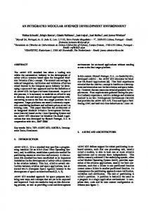
Their task is the generation of executable TTCN-3 code from ITML models. As presented in section 3.2.4, the MetaEdit+ framework provides a special generator language, called MERL, in which generators can be written. While MERL (itself being a DSL) is well suited for navigating graphical GOPPRR-based models and creating output text files, it lacks some more general-purpose programming concepts like custom data types, scoped variables, and custom functions. Consequently, depending on the complexity of the task demanded from the generator, it can be deemed impractical to implement the generator completely in MERL. A reasonable solution to this problem is to have a very simple generator, written in MERL, which generates a file containing an intermediate representation of the model. Then this intermediate file can be processed by a more complicated generator written, for example, in a general-purpose language like C++ or Python. 10.1 MERL Intermediate Format Generators
As the task of generating executable TTCN-3 code from ITML models is rather complex and involves more inputs than just the model—also an external configuration in ICD format—it is not feasible to implement the whole generator in MERL. Instead, the ITML generators written in MERL produce files containing intermediate XML representations of the different model graphs. These generators are called MERL Intermediate Format Generators (IFGs). For each graph type there is a dedicated IFG. Their definitions can be found in appendix E as MERL source code. As can be seen in figure 10.1, the IFGs produce XML representations of the model inputs. XML schemas have been defined for these XML file formats. The appro135
10
ITML-B only
CHAPTER 10. TEST GENERATION
Configuration Model
Behaviour Model
MERL IFG
MERL IFG
XML Configuration
XML Behaviour
MetaEdit+ ITML Framework Test Environment
ICD-Gen
ICD
Test-Gen
ICD Parser TA Source
TA Configuration
TTCN-3 Source
C Compiler
TTCN-3 Compiler
TA Load
Executable Test Procedure
Framework Library
Figure 10.1: ITML-B and ITML-C generation process
priate XML Schema [W3C04] definitions can be found in appendix F. The intermediate XML files contain information about what objects are present in a graph, what properties the objects have, and by what relationships they are connected. The exact graphical layout of the graph elements, however, is not stored inside the XML files, as this information is not relevant for the generation process.
10.2 Generation of ITML-B and ITML-C Tests
Figure 10.1 provides an overview of the generation process within the ITML framework. It shows generators (rectangles) and artefacts (rounded boxes), which are the generator inputs and outputs. 136
10.2. GENERATION OF ITML-B AND ITML-C TESTS
10.2.1 ICD Generator
The ICD Generator (ICD-Gen) is employed within the ITML framework to create actual ICDs from Configuration XML files (produced by the IFG). Note that this step is only performed for Bare Module testing in ITML-B, whereas ITML-C works with externally supplied configurations. The generator reads an XML intermediate configuration file and produces a set of CSV files. For each partition defined in the configuration model, two files are generated. They contain configuration information as described in section 2.3, derived from the XML configuration file contents. The files are generated so that they are suitable for processing with the module-specific configuration and load generation toolchain as provided by the module supplier¹. The ICD Generator is a command-line application written in C++. It uses the XSD Data Binding compiler [CST] to parse the XML input file and has its own CSV file export routines. Due to its size the complete source code is not reproduced here. 10.2.2 ICD Parser
After generating the ICD as described in the previous section, or when using an external ICD, it has to be processed further. The test generator itself requires it as input (cf. next section), but it is also required in order to generate the partition-specific part of the universal Test Agent (cf. chapter 7). While the agent main loop and protocol handling code are completely generic, the agent requires two data tables containing information about the API ports defined within the partition and the data signals which may be defined within API port messages. To that end, the ICD parser is used to generate a C source file containing two appropriate data structures. The ICD parser is a command-line application written in Perl. It is based on a previous parser which the author developed during his work in the VICTORIA research project. The resulting TA configuration C source file can now be combined with the rest of the TA source code and processed by the compiler, linker, and load generation tools provided by the module supplier. The generated load is then ready for deployment on the SUT module. 10.2.3 TTCN-3 Code Generator
As shown in figure 10.1, there is a second path of generation, i. e. the processing of the Behaviour. After having employed the Behaviour IFG in order to obtain a behaviour XML file, it must be processed by the TTCN-3 Test Generator (Test-Gen). This generator takes two inputs: The aforementioned behaviour XML file, but also the ICD (either generated or supplied externally) associated with the behaviour model (as defined in the test suite). ¹The manufacturer of the IMA module
137
CHAPTER 10. TEST GENERATION
The test generator is the most complex of the generators described here because it has to generate TTCN-3 code that results in API calls conforming to the dynamic behaviour of its input model and configuration as specified by the behaviour transition system defined in section 9.2.4. The TTCN-3 Test Generator is a command-line application written in C++. It uses the XSD Data Binding compiler [CST] to parse the XML input file and has its own CSV file import routines. Due to its size the complete source code is not reproduced here. Goto Considered Harmful
A rather straight-forward method of generating code from a flowchart is to create a blocks of statements prefixed by a unique label for each node and to generate a goto statement for each edge between nodes. ... // node 1 label b1; stmt1; stmt2; if (cond1) { goto b2; } goto b3; // node 2 label b2; stmt3; stmt4; goto b3; ...
Unfortunately, it was discovered during development of the generator that the TTCN-3 compiler in TTworkbench only supports a limited number of labels and gotos per file. Exceeding this limit results in syntactical errors in the generated Java source. Note that the Java language has no direct support for goto (cf. [ORC]), so the TTCN-3 compiler uses a construct of loops and switch statements to simulate it. A practical work-around for this problem was to perform this simulation of gotos directly in TTCN-3 instead of using gotos in the TTCN-3 code. This can easily be achieved by declaring a variable node to be used as the current label and then generating the statements for each node inside a sequence of if-blocks. All these if-blocks are encapsulated within a whileloop. Now, instead of performing a goto statement, the node variable is set to the number of the next node, and a continue statement is used to restart the while loop. 138
10.3. GENERATION OF ITML-A TESTS
int node := 1; while (node != 0) { // node 1 if (node == 1) { stmt1; stmt2; if (cond1) { node := 2; continue; } node := 3; continue; } // node 2 if (node == 2) { stmt1; stmt2; node := 3; continue; } ... }
10.3 Generation of ITML-A Tests
The ITML-A generation process is shown in figure 10.2. While similar, it is not identical to the process shown before. The following steps make use of rtt-tcgen, the model-based testing environment developed by the AGBS research group² at the University of Bremen. Like before, a MERL IFG is used to produce an intermediate XML representation of the system model. The corresponding generator can be found in appendix E.5. The XML schema for the intermediate format is presented in appendix F.5. Before the XML model export can be processed by the actual test case generator, it must be processed by two additional tools. conftool creates a configuration file for the test case generator. It contains a list of all components and the transitions inside their statecharts. The test engineer can use this file to set focus points (transitions that must be covered) or mark transitions as unreachable or robustness transitions. ²http://www.informatik.uni-bremen.de/agbs/
139
CHAPTER 10. TEST GENERATION
System Model
MetaEdit+ ITML Framework
MERL IFG
Test Environment
XML Model conftool
sigmaptool
Configuration
Signal map
rtt-mbt-ttcn3 TTCN-3 Source
Framework Library
TTCN-3 Compiler Executable Test Procedure
Figure 10.2: ITML-A generation process sigmaptool creates a table containing all signals (i. e. SUT inputs and outputs) defined in the system model. The value ranges as defined in the model can be adjusted by the user. Tolerances and signal delays/latencies can be specified as well. The files created by the aforementioned tools are in CSV format. Their contents can be adjusted, if necessary, by the test engineer before they are processed together with the XML model export by the test case generator. 10.3.1 Test Case Generator
The actual TTCN-3 test case generator tool is based on existing test case generators in the rtt-tcgen framework. The executable is called rtt-mbt-ttcn3. It reads the system XML model, the configuration, and the signal map as inputs and creates a TTCN-3 source file as output. 140
10.3. GENERATION OF ITML-A TESTS
SUT Memory Model SUT Abstract Model
Intermediate Model Representation
ITML-A, UML, ...
SUT Model Parsers
Test Strategy
Symbolic Test Case Generator (Path Selector)
Constraint Generator
Interpreters Symbolic
Constraint Solvers Interval Analysis
Linear Arithmetic
Abstract
String Bit Vector
Boolean
Solution Set Approximation Test Data: Input Assignment
Figure 10.3: Test Case Generator architecture Model Parser
The generator first reads the configuration file. Then it tries to parse the model. The generator has several parser back-ends, each of which is applied in turn until one successfully parses the model file. Apart from ITML there are parser back-ends available for model exports from other modelling tools like Artisan, Enterprise Architect, or Rhapsody. The purpose of the parser back-ends is to transform the contents of the model input file into the intermediate model representation (IMR) structure used internally in the generator. Compared to other model export formats, the ITML intermediate XML format is very simple, which makes the parsing and transformation step very straightforward. Generator
While rtt-mbt-ttcn3 makes use of the test case generation functionality of rtt-tcgen, the internal workflow of the generator is not a part of this thesis. It is described in detail in [Pel13], and only a short summary will be given here. Figure 10.3 shows the internal structure of the generator. From the intermediate model representation a transition relation and initial state are gen141
CHAPTER 10. TEST GENERATION
erated. According to the configured test strategy, model paths are selected. Such paths, expressed as LTL formulae, are transformed to so-called symbolic test cases (cf. [Pel13, p. 14]). Now an SMT solver (cf. [RT06]) is employed to find a solution in the form of a valid trace from the initial state to the desired goal (test objective) in compliance with the model’s transition relation. An abstract interpreter supports the solver by determining required transition steps and restricting variable ranges. If a solution exists, the result is a trace of timestamps and concrete input data for the test procedure. TTCN-3 Output
The results of the previous step are then processed by the TTCN-3 output back-end. The back-end’s task is the creation of a TTCN-3 source file containing a test procedure which covers the generated test cases. The generated TTCN-3 file has the following structure: • port type declarations • MTC component – – – – – – – – –
ports I/O variables state variables cycle timer global time-tick variable oracle functions stimulator function input function output function
• testcase – main loop For each input and output signal from the signal map a TTCN-3 port type declaration with appropriate data type and direction (TTCN-3 output port for SUT inputs, TTCN-3 input port for SUT outputs) is generated. The MTC component contains a corresponding port definition for each signal, so that it can communicate with the SUT via the SUT adapter (cf. section 5.4). For each port there is also a component variable (called input variable or output variable). The TTCN-3 testcase is generated to start a cycle timer and execute an endless loop consisting of four steps: 1. call input function 142
10.3. GENERATION OF ITML-A TESTS
2. call oracle functions 3. call stimulator function 4. call output function The input function consists of an alt statement over all input ports (i. e. SUT output signals) plus the cycle timer. If a value can be read from an input port, it is stored in the corresponding input variable. Then the alt statement is repeated. The statement is only left when the cycle timer expires, in which case the timer is restarted, the cycle time is added to the global time-tick variable, and the main loop proceeds to the oracle functions. The TTCN-3 output back-end generates a set of oracle functions. It traverses the IMR to find all leaf components. From each component’s statechart it creates an abstract syntax tree (AST), which is then translated into TTCN-3 code as the body of the component’s oracle function. A branch is added to the AST of the function for each location of the statechart. If a location contains do actions, they are added to the AST branch. From each location all outgoing transitions are considered. For each outgoing transition an if statement is added to the AST branch with the transition’s guard as condition. The body of the if statement contains the transition’s actions and the entry actions of the destination location as well as an assignment of the new location to the oracle’s state variable in the MTC. In other words, running the oracle functions creates the same variable and signal assignments as the SUT should do. This allows the oracle functions to run back-to-back with the SUT and perform a comparison of the expected (as calculated by the oracle) and actual SUT output signals. The oracle function contains log statements printing the respective requirements to the test log, and setverdict statements to log the result of the comparison of actual and expected values. The purpose of the stimulator function is to provide stimuli to the SUT in order to cover the test cases determined by the generator. The stimulator function implements a simple state machine. Its current state is stored in a component variable of the MTC. Depending on the global time-tick, the function makes assignments to output variables. The TTCN-3 output backend traverses the computation tree built by the generator to determine the points in time and examines the internal memory model to determine the assignments on output variables (i. e. SUT inputs) to be made. When the stimulator function reaches the end of its state machine, it terminates the test procedure by executing the stop statement. Finally, the output function is called. This function checks if the values of output variables have changed during this cycle. For each changed variable, its new value is sent via the corresponding port to the SUT. Then the main loop starts again with the input function. 143
CHAPTER 10. TEST GENERATION
Test Execution
The generated TTCN-3 source file contains the complete test procedure implementation in order to cover the test cases generated by the test case generator from the model. The test engineer can now compile the test procedure in the TTCN-3 test execution environment (cf. chapter 8). Note, however, that for functional testing the TACP sub-SA must be removed from the SUT adapter (because there are no agents involved). Instead, the adapter must map the defined signal ports to the appropriate hardware interfaces of the module (by consulting the list of signals in the actual module ICD as specified by the module integrator).
144
PART
III
Evaluation
CHAPTER
Usage in the SCARLETT Project
As already mentioned earlier, the ITML framework is based in part on
research performed within the European research project SCARLETT (cf. section 2.5). During work package WP2.4 (Toolset & Simulators Development) a test case generation and execution process was defined (project-internal deliverable SCA-WP2.4-ADE_TECH-D_2.4-01-ICI4). Based on this process, specifications for the framework components (DSL, Test Agent, generator tools) were elaborated (SCA-WP2.4-ADE_TECH-D_2.4-02-ICI7). Mockups and working prototypes of the framework components were developed in order to complete the work package. Afterwards, the developed components were used in the demonstration phase of the project. In work package WP4.2 (I/O Intensive Capability Demonstration), a demonstration platform was built to showcase IMA2G technology in I/O-intensive setups. 11.1 I/O-intensive Scenarios
Several scenarios were defined in WP4.2 in order to perform I/O-intensive tests on the available IMA2G hardware. In these scenarios the Test Agent was running on a CPM, providing stimuli to various interface hardware. In order to produce the load for the CPM, the ICD (provided by the platform integrator) was processed with the TA configuration parser. Then the resulting configuration tables and the generic Test Agent source code 147
11
CHAPTER 11. USAGE IN THE SCARLETT PROJECT
were compiled with the Wind River C compiler. The resulting image was downloaded to the module with an ARINC 615A data loader (cf. [Aer07a]). The test environment consisted of TTworkbench as a TTCN-3 environment and an ADS2 system for access to hardware interfaces. The Wireshark plug-in was utilised as well to analyse communication between the test environment and the Test Agent. A prototype version of the test generator was used to generate appropriate TTCN-3 test procedures for the individual scenarios. These test procedures were compiled together with the Proxy SA, the TACP SA, and an ADS2 SA and then executed within TTworkbench. 11.1.1 Scenario 1
The first scenario consists of a CPM, an AFDX switch, and two RDCs. The RDCs are connected to the CPM via the switch. The two RDCs are connected to each other: Each discrete output of RDC 1 is wired to a discrete input of RDC 2 and vice versa. Similarly, analogue outputs are wired to analogue inputs. The CAN buses of the RDCs are linked as well. The Test Agent is employed to command the RDCs to toggle each output discrete and then read back the corresponding input discrete from the other RDC. It does the same by applying different voltages to the analogue outputs and reading the active voltage back from the connected analogue input. CAN bus messages are sent in both directions and received from the respective other endpoint. 11.1.2 Scenario 2
The second scenario consists of a CPM, an AFDX switch, an REU, and a stepper motor. The REU is connected to the CPM via the AFDX switch, while the control interface of the stepper motor is connected to a special interface of the REU. The stepper motor also has a read-back interface, which is connected to the test environment. In this scenario the test procedure commands the Test Agent to send positioning commands to the stepper motor. The test procedure checks the correct rotation by reading the current angle from the test environment (ADS2 interface). 11.1.3 Scenario 3
The third scenario consists of a CPM, an AFDX switch, an RDC, and a DC bus monitor. The RDC is connected to the CPM via the AFDX switch. Two DC bus interfaces of the RDC are connected with each other (loop-back), with the DC bus monitor in between. The Test Agent is used to repeatedly send and receive messages over the DC bus loop-back connection. In parallel, the DC bus monitor is employed to simulate noise and to add attenuation to the bus connection (this must 148
11.1. I/O-INTENSIVE SCENARIOS
be done manually as the monitor has no direct interface to the test environment). 11.1.4 Scenario 4
The fourth scenario consists of a CPM, an AFDX switch, an REU, and RDC, and an RPC. The REU is connected to the CPM via the AFDX switch. The RDC and the RPC are connected to the REU via FlexRay in a star topology (i. e. the REU is used as a FlexRay gateway). Discrete inputs and outputs of the RDC and RPC are connected to the test environment. In this scenario the test procedure commands the Test Agent to send commands to the RDC and RPC via the REU in order to toggle the outputs of the RDC and the RPC. The test procedure checks the appropriate inputs of its test environment. Conversely, it toggles discrete outputs of the test environment connected to the discrete inputs of the RDC and commands the Test Agent to read back those inputs from the RDC. 11.1.5 Models
During the implementation of the framework and generators, they were tested with more generic example test models (i. e. not specific to the SCARLETT I/O-intensive demonstrator). These models are shown and described in appendix A.
149
CHAPTER
Comparison with Other Tools and Approaches
In order to give an evaluation of ITML, it is important to take a look at the intended goals. The key aspects which must be considered are:
Learning curve: A domain expert who has not used the framework before should be able to start using it without having to invest time in learning and/or memorising additional languages and/or concepts. Intuitiveness: The meaning of the framework or language elements should be intuitively clear to a domain expert. Efficiency: The use of the framework should provide an increase in efficiency, i. e. reduce work effort and ultimately save money. Maintainability: It should be easily possible to adapt previously created tests to changes in requirements or in the test environment. A person different from the original author should be able to understand existing tests and make changes. 12.1
TTCN-3
The first and very interesting question is: How does ITML compare to “bare” TTCN-3? Is it worth having another layer on top of a language designed specifically for testing? A domain expert who has never written any TTCN-3 code will first have to learn several concepts of the language. And while this is not overly difficult for someone who has at least some experience in programming, there are 151
12
CHAPTER 12. COMPARISON WITH OTHER TOOLS AND APPROACHES
several unique aspects of which a deeper understanding is required in order to successfully employ TTCN-3 (cf. chapter 5, e. g. templates, ports, codecs). In contrast, the elements of ITML have a counterpart in the application domain, and therefore the domain expert is already familiar with them. It is also important to note that ITML works on a higher abstraction level than TTCN-3. This becomes particularly apparent when considering API calls in ITML-B. To perform an API call in ITML-B requires in its simplest form a single language element. In TTCN-3 the programmer will have to take care of creating a command message, handling the TACP protocol, and receiving the response message. Note, however, that in both cases (ITML and TTCN-3), an appropriate SUT adapter provides abstraction from the specifics of accessing the TE interface hardware (and therefore allowing changes in the test environment). The graphical representation of ITML test models makes it possible to understand them easily. The graph editor provided by MetaEdit+ is well suited to make modifications to existing models with manageable effort. It is also interesting to note that the TTCN-3 standard defines a graphical representation of TTCN-3 test procedures, called GFT (cf. [ETS07]). It provides graphical representations for the TTCN-3 core language elements. The standard defines a mapping between the language and the GFT. This, however, means that GFT does not provide a higher level of abstraction as ITML does. Two very important disadvantages of TTCN-3 must not be ignored: The first is its lack of support for the sampling port concept (cf. section 2.2.2). This, however, can be remedied by making sure that re-transmissions occur on SUT adapter or hardware level as well as storing the last received value of a port in a variable (also note [SP13] for an interesting alternative concept). The second aspect is that while TTCN-3 was designed for testing, it was originally not designed for real-time testing. This becomes readily apparent in the implementation of oracles and test stimulators in section 10.3.1: TTCN-3 does not provide the concept of clocks, so they have to be simulated with timers and counter variables. This leads to clock drift and a multitude of “timeouts” in the TTCN-3 test logs. It should be noted, however, that several extensions to the TTCN-3 standard have been proposed in order to make it real-time-capable (cf. [SMD+ 08]). 12.2 CSP
As already mentioned in the introduction, in an earlier research project a bare module test suite had been developed. The test specifications were written in CSP (cf. [Hoa78, Sch00]). Compared to ITML, the use of CSP poses a significantly higher obstacle for a domain expert, as knowledge of the domain alone is not sufficient. In order to understand or even write new specifications, the test engineer re152
12.3. UML TESTING PROFILE
quires a deep understanding of the syntax and semantics of CSP. Also, the test engineer receives no tool support¹ during the development of test specifications and has to rely on “trial and error” techniques (i. e. writing CSP code, trying to compile it, fixing compilation errors). In contrast, MetaEdit+ provides a much more intuitive user interface for ITML: In the graph editor, the user can see what types of objects and relationships are available. There is no need to remember names or keywords for language features or grammar rules. The automatic compliance with the rules of the metamodel enforced by the framework guarantees a syntactically correct test specification model. The fact that CSP specifications are difficult to understand greatly affects their maintainability. Before making changes to an existing CSP specification it takes additional effort to analyse the current behaviour for a test engineer unfamiliar with the existing test suite. There is, however, an important similarity between ITML and CSP: Both operate on an abstract level, hiding details of hardware interface access from the test specification. In fact, for CSP tests one or more interface modules are required, which have to provide a refinement from the abstract CSP events to physical signals on hardware interfaces to the SUT and vice versa. A great advantage of the ITML framework is, of course, the fully automatic generation of test cases from application models with ITML-A. In contrast, test cases had to be derived and translated into appropriate CSP specifications completely by hand. 12.3
UML Testing Profile
The third and final object of comparison is the UML Testing Profile (UTP, cf. [OMG13]). UTP is a UML profile, extending UML to allow the definition and specification of testing-related artefacts (either stand-alone or within a “regular” UML model of an application or system). UTP defines concepts to describe the structure of the test setup (SUT, TestComponent, TestContext). Test behaviour can be modelled with UML behaviour diagrams (e. g. activity diagram or state machine). Test behaviour consists of actions like SUT stimulation, logging, or test verdict calculation (validation actions). There are special concepts provided in order to specify test data: data pools, partitions, and selectors. Furthermore, the concept of test objectives supports the planning and scheduling of tests. It quickly becomes apparent that, in terms of generalisation, UTP is the exact opposite of ITML. UTP is a general-purpose modelling language, while ITML is domain-specific, even though they are both designed for testing. In order to work with UTP, the test engineer must know and understand the special concepts of UTP in addition to the application domain. It can, ¹apart from simple syntax colouring
153
CHAPTER 12. COMPARISON WITH OTHER TOOLS AND APPROACHES
however, be argued that the learning curve should be relatively shallow, since these concepts are all testing-related. UTP itself is not a complete framework, but only a language. Additional tool support for the modelling as well as for the translation of test case models into executable test procedures is required. Therefore, an appropriate set of tools must be chosen, and the test engineer must be familiar with it. Note that there is no direct support for the automatic generation of test cases like in ITML-A. Instead, test cases are modelled explicitly, like in ITML-B/C. Like ITML, the fact that UTP modelling is independent from specific test environment hardware increases its maintainability. The fact that UML is widely known also increases the chances of a person different from the original modeller to understand and adapt existing models. For a more detailed introduction to and discussion of UTP topics, refer to [BDG+ 08].
154
CHAPTER
Conclusion
T
he goal of this thesis was the design and development of a framework for model-based testing of Integrated Modular Avionics systems. The key approach to this goal was the utilisation of domain-specific modelling techniques. This approach was motivated by the wish to give IMA domain experts a state-of-the-art tool that can be used with a minimum of learning effort and allows a more productive way of working compared to manually developing test procedures. 13.1
Results
The main contributions provided by this thesis are described in detail in part II. These contributions together make up the model-based testing framework. The domain-specific modelling language ITML has been defined in order to provide a means to specify tests and desired system behaviour. Due to its domain-specific nature its concepts are easily understood by IMA domain experts. Its level of abstraction makes it possible to work directly on the problem level instead of having to cope with the technical details of a specific test environment. ITML comes in three variants, ITML-A, ITML-B, and ITML-C, in order to adequately cover different levels of testing. For all variants formal definitions of abstract syntax as well as static and dynamic semantics are provided. An implementation of all language variants is provided in the form of meta-models in the DSM tool MetaEdit+. This tool provides an appropriate modelling front-end to be used by IMA domain experts. Furthermore, generators have been implemented that automatically produce executable TTCN-3 test procedures based on the models designed by the domain expert. 155
13
CHAPTER 13. CONCLUSION
The framework also provides a suitable TTCN-3-based test environment. This includes appropriate system adapters and codecs which can be used, for example, in TTworkbench. The choice of TTCN-3 has the advantage of having test procedures which are independent from the underlying concrete test system (due to the interfaces defined by the TTCN-3 standard). To complement the TTCN-3 test environment, the framework provides an implementation of a flexible and universal Test Agent. The agent is ARINC 653-compatible and is therefore suited for loading onto the target module under test. The agent can execute API calls on behalf of the running test procedure. As a means of controlling the agent, a control protocol has been specified, and the framework comes with a suitable protocol implemention in the test environment. The appendix of this thesis contains a series of example ITML models. When comparing the graphical model representations with the TTCN-3 code generated from them, it becomes easily apparent that an IMA domain expert can work more effortlessly and efficiently by creating ITML models compared to manually writing test procedures and that these models have a higher comprehensibility compared to TTCN-3 code. 13.2 Future Work
For future work, two interesting points remain: One important aspect of the ITML framework is usability. In order to further substantiate the conclusions drawn concerning framework usability in chapter 12, a case study with IMA domain experts should be conducted. This could be performed according to the evaluation techniques described, for example, in [GP96]. The other point concerns the user interface. Currently, several separate tools have to be employed in order to follow the process workflow detailed in chapter 6. From a usability perspective, it would be preferrable to have a unified user interface that provides all functionality, from modelling to test execution, inside a single front-end application. The Eclipse framework, for instance, provides a suitable platform into which all the different tool components required for IMA testing could be integrated.
156
PART
IV
Appendices
APPENDIX
Example Models
This appendix shows several example models, both ITML-B and ITML-A. It also shows generated intermediate XML files as well as generated TTCN-3 code.
A.1 ITML-B
Figure A.1 shows an ITML-B configuration model. It consists of a CPM containing two partitions. Both partitions have appropriate scheduling and RAM settings. Partition 9 has a group of AFDX input ports, while partition 10 has a group of AFDX output ports. Both partitions are connected via a group of RAM ports. Figure A.2 shows an ITML-B behaviour model. It shows how the blackboard API (cf. section 2.2.2) can be tested: In the init process, a blackboard and two processes are created. Then the partition is switched into normal mode. The first process writes a message to the blackboard by making a DISPLAY_BLACKBOARD API call, then the second process tries to read the message via READ_BLACKBOARD. If the call succeeds, the test verdict is set to passed, otherwise the test has failed. Figure A.3 shows an example model for port handling. The init process opens all AFDX sampling output ports of the partition in a loop. Then it creates a process and sets the partition to normal mode. The created process then iterates over all previously created ports and writes a message to each port by calling WRITE_SAMPLING_MESSAGE. Then a read complement is used to receive the message (in the test environment). If writing or reading fails, the test verdict is set to failed, otherwise the test is passed. Figure A.4 is very similar to the previous model. The test starts by creating all RAM sampling input ports in partition 10 and creating a process, 159
A
APPENDIX A. EXAMPLE MODELS
CPM THA Pos. 1
AFDX Ports
AFDX Ports
Queuing Size: 1024 B Count: 12
Sampling Size: 64 B Count: 10
Partition 9
RAM Ports
Partition 10
Period: 1000 ms Duration: 500 ms RAM Size: 4096 KiB
Sampling Size: 512 B Count: 16
Period: 1000 ms Duration: 200 ms RAM Size: 8192 KiB
Figure A.1: Configuration model followed by creating all RAM sampling output ports and a process in partition 9. Each partition is switched to normal mode afterwards. Then the process in partition 9 iterates over the previously opened ports and writes a message to each port. The following read complement will cause the process in the other partition to perform a READ_SAMPLING_MESSAGE on the appropriate input RAM sampling port (cf. RAM port configuration in figure A.1). If all messages are successfully received, the test is passed, otherwise the verdict is set to failed. Appendix A.1.1 shows the intermediate XML representation that was created from the model in figure A.2 by the generator shown in appendix E.2. It contains four sections. The first two, resources and nodes, contain XML representations of the objects shown in the behaviour model (i. e. parameter objects like blackboard and processes in the resources section, API calls in the nodes section). The other two sections, parameters and controlflow, contain XML representations of the relationships between the objects in the model, i. e. parameter assignments to API calls and control flow edges. Appendix A.1.2 finally shows the TTCN-3 test procedure generated by the ITML-B test generator from the intermediate XML representation in appendix A.1.1. The individual nodes are translated into procedure calls to the TACP handler. The function run_Blackboard implements the behaviour of the flowchart as described in section 10.2.3.
160
A.1. ITML-B
START
Partition 9
Init Process
Create Blackboard
Process p1
Create Process
Start
Process p2
Create Process
Start
Set Partition Mode NORMAL
Process p1 Blackboard
Display Blackboard bb01 Size: 64 B Message Pattern
Process p2
0xFF
Read Blackboard INVALID_MODE INVALID_PARAM NOT_AVAILABLE TIMED_OUT FAIL
NO_ERROR PASS
Figure A.2: Blackboard API test model
161
APPENDIX A. EXAMPLE MODELS
START
Partition 10
Init Process AFDX Sampling Output Port Loop Create Sampling Port Loop End
Create Process Process p1 Start
Set Partition Mode NORMAL
Process p1
Loop AFDX Sampling Output Port Write Sampling Message NO_ERROR
INVALID_CONFIG INVALID_MODE INVALID_PARAM
FAIL
Message Pattern 0xFF
Read complement
INVALID_CONFIG INVALID_MODE INVALID_PARAM NOT_AVAILABLE TIMED_OUT
NO_ERROR Loop End
PASS
Figure A.3: AFDX port API test model
162
FAIL
Process p2
RAM Sampling Input Port
Set Partition Mode NORMAL
Set Partition Mode NORMAL Process p2
Start
Start
Create Process
Loop End
Loop End
Process p1
Create Sampling Port
Create Sampling Port
Create Process
Loop
RAM Sampling Output Port
Init Process
Partition 9
Loop
Init Process
Partition 10
START
RAM Sampling Output Port
Figure A.4: RAM port API test model PASS
Loop End
NO_ERROR
Read complement
NO_ERROR
INVALID_PARAM INVALID_CONFIG INVALID_MODE
0xFF
INVALID_PARAM INVALID_MODE INVALID_CONFIG NOT_AVAILABLE TIMED_OUT
Message Pattern
Write Sampling Message
Loop
Process p1
FAIL
FAIL
A.1. ITML-B
163
APPENDIX A. EXAMPLE MODELS
A.1.1 Intermediate XML Representation
INVALID_MODE INVALID_PARAM NOT_AVAILABLE TIMED_OUT NO_ERROR
164
A.1. ITML-B
A.1.2 TTCN-3 Code // Generated by ITML-B/C Test Generator 1.0 on 2014-Jun-21 16:26:06 // from model ”Blackboard.xml” // Configuration: // ”COMMANDPORTS.csv” // ”L1G0000M09V001I001.csv” // ”L1G0000M10V001I001.csv” // ”L1L0000M09V001I001.csv” // ”L1L0000M10V001I001.csv” // ”L1M0000M00V001I001.csv” module m_Blackboard { import from types all; import from TACP all; type component MTCType { port CmdPort cmd_p9; } type component SUTType { port TACP_Out_Port TZI_TA_P9_CMD_IN; port TACP_In_Port TZI_TA_P9_CMD_OUT; } function run_Blackboard() runs on MTCType { var charstring node; var RETURN_CODE_TYPE return_value; timer complement_timer; var integer p9_blackboard_bb01_id; template charstring p9_msg3_1840_pattern := ”0xFF0xFF0xFF0xFF0xFF0xFF0xFF0xFF”; var integer p9_process_p2_id; var integer p9_process_p1_id; // pre-fill data table cmd_p9.call(SET_DATA_TABLE_ENTRY:{0, ”bb01”, -}) { [] cmd_p9.getreply(SET_DATA_TABLE_ENTRY:{-, -, NO_ERROR}); } cmd_p9.call(SET_DATA_TABLE_ENTRY:{1, p9_msg3_1840_pattern, -}) { [] cmd_p9.getreply(SET_DATA_TABLE_ENTRY:{-, -, NO_ERROR}); } cmd_p9.call(SET_DATA_TABLE_ENTRY:{2, ”p2”, -}) { [] cmd_p9.getreply(SET_DATA_TABLE_ENTRY:{-, -, NO_ERROR}); } cmd_p9.call(SET_DATA_TABLE_ENTRY:{3, ”p1”, -}) { [] cmd_p9.getreply(SET_DATA_TABLE_ENTRY:{-, -, NO_ERROR}); } node := ”node_3_1527”; while (node != ””) { if (node == ”node_3_1527”) { // start node := ”node_3_1537”; continue; } if (node == ”node_3_1537”) { // partition 9 node := ”node_3_2105”; continue; } if (node == ”node_3_2105”) { // process INIT cmd_p9.call(set_process_idx:{0}) {
165
APPENDIX A. EXAMPLE MODELS
[] cmd_p9.getreply(set_process_idx:{-}); } node := ”node_3_1596”; continue; } if (node == ”node_3_1596”) { // Create_Blackboard cmd_p9.call(CREATE_BLACKBOARD:{0, 64, -, -}) { [] cmd_p9.getreply(CREATE_BLACKBOARD:{-, -, ?, ?}) -> param(-, -, p9_blackboard_bb01_id, return_value); } node := ”node_3_1617”; continue; } if (node == ”node_3_1617”) { // Create_Process cmd_p9.call(CREATE_PROCESS:{3, 0, 32768, 1, 1000, 500, SOFT, -, -}) { [] cmd_p9.getreply(CREATE_PROCESS:{-, -, -, -, -, -, -, ?, ?}) -> param(-, -, -, -, -, -, -, p9_process_p1_id, return_value); } node := ”node_3_1692”; continue; } if (node == ”node_3_1692”) { // Start cmd_p9.call(START:{p9_process_p1_id, -}) { [] cmd_p9.getreply(START:{-, ?}) -> param(-, return_value); } node := ”node_3_1782”; continue; } if (node == ”node_3_1782”) { // Create_Process cmd_p9.call(CREATE_PROCESS:{2, 0, 32768, 0, 1000, 500, SOFT, -, -}) { [] cmd_p9.getreply(CREATE_PROCESS:{-, -, -, -, -, -, -, ?, ?}) -> param(-, -, -, -, -, -, -, p9_process_p2_id, return_value); } node := ”node_3_1785”; continue; } if (node == ”node_3_1785”) { // Start cmd_p9.call(START:{p9_process_p2_id, -}) { [] cmd_p9.getreply(START:{-, ?}) -> param(-, return_value); } node := ”node_3_1715”; continue; } if (node == ”node_3_1715”) { // Set_Partition_Mode cmd_p9.call(SET_PARTITION_MODE:{NORMAL, -}) { [] cmd_p9.getreply(SET_PARTITION_MODE:{-, ?}) -> param(-, return_value); } node := ”node_3_2112”; continue; } if (node == ”node_3_2112”) {
166
A.1. ITML-B
// process p1 cmd_p9.call(set_process_idx:{p9_process_p1_id}) { [] cmd_p9.getreply(set_process_idx:{-}); } node := ”node_3_1744”; continue; } if (node == ”node_3_1744”) { // Display_Blackboard cmd_p9.call(DISPLAY_BLACKBOARD:{p9_blackboard_bb01_id, 1, 32, -}) { [] cmd_p9.getreply(DISPLAY_BLACKBOARD:{-, -, -, ?}) -> param(-, -, -, return_value); } node := ”node_3_2119”; continue; } if (node == ”node_3_2119”) { // process p2 cmd_p9.call(set_process_idx:{p9_process_p2_id}) { [] cmd_p9.getreply(set_process_idx:{-}); } node := ”node_3_1865”; continue; } if (node == ”node_3_1865”) { // Read_Blackboard cmd_p9.call(READ_BLACKBOARD:{p9_blackboard_bb01_id, 0, 1, -, -}) { [] cmd_p9.getreply(READ_BLACKBOARD:{-, -, -, ?, ?}) -> param(-, -, -, -, return_value); } if (return_value == INVALID_MODE or return_value == INVALID_PARAM or return_value == NOT_AVAILABLE or return_value == TIMED_OUT) { node := ”node_3_1909”; continue; } if (return_value == NO_ERROR) { node := ”node_3_1912”; continue; } node := ””; continue; } if (node == ”node_3_1909”) { setverdict(fail); node := ””; continue; } if (node == ”node_3_1912”) { setverdict(pass); node := ””; continue; } } } testcase Blackboard() runs on MTCType system SUTType { timer tacp_sync := 1.0; var TACPHandler p9_handler;
167
APPENDIX A. EXAMPLE MODELS
p9_handler := TACPHandler.create; map(p9_handler:tacpToCPM, system:TZI_TA_P9_CMD_IN); map(p9_handler:tacpFromCPM, system:TZI_TA_P9_CMD_OUT); connect(mtc:cmd_p9, p9_handler:cmd);
p9_handler.start(runHandler()); tacp_sync.start; tacp_sync.timeout; run_Blackboard(); } }
Due to their size the intermediate XML representations and the generated TTCN-3 test procedures for the other models are not reproduced here.
168
A.2. ITML-A
SUT Input Signals
SUT Output Signals
SD1A_state: int SD1B_state: int
Fire_Detected: bool Maintenance_Required: bool
Test Environment (TE)
Constants CPM THA (SUT)
Standby: int = 0 Failed: int = 1 Alarm: int = 2
Figure A.5: System diagram
FSD
Figure A.6: System Under Test component diagram A.2 ITML-A
The remainder of this appendix shows a complete ITML-A example: a Fire and Smoke Detection application (FSD), as commonly used in modern commercial aircraft. The system consists of smoke detectors (SD) which are installed in different areas of the aircraft, e. g. lavatories, galleys, or cargo compartments. The smoke detectors are connected to a data bus, which links them to the module hosting the FSD application. The application receives status updates from the smoke detectors and determines if a fire has been detected. Upon detection the application signals the flight crew and triggers fire extinguishing measures. If a smoke detector fails, the application gives a signal that on-ground maintenance is required. Figure A.5 shows the system diagram for the FSD application. It consists of an SUT component representing a CPM and the test environment (TE). The signal lists show the input and output signals that the SUT provides towards the TE. In particular, SD1A_state and SD1B_state are smoke detector status inputs, while Fire_Detected and Maintenance_Required are outputs from the application. The constants list contains values for the encoding of the smoke detector status in the SD status signals. Figure A.6 shows the interior of the SUT component: The SUT decomposes into a single component representing the FSD application running on the module. Analogously, figure A.7 shows the decomposition of the TE: It consists of a simulation component representing smoke detector SD1. The SD1 component decomposes further into another component dia169
APPENDIX A. EXAMPLE MODELS
SD1 Sim
Figure A.7: Test Environment component diagram
SD1A Sim
Variables t_rep: timer
SD1B Sim
Figure A.8: SD1 simulation component diagram gram shown in figure A.8. The smoke detector SD1 consists of two individual detectors, SD1A and SD1B. Therefore, SD1 represents a so-called dual smoke detector, providing fault tolerance. Inside this component a timer, t_rep, is defined. Its purpose will be explained below. The simulation components SD1A and SD1B decompose into the statecharts shown in figure A.9 and figure A.10, respectively. Each detector has three primary states, Standby, Alarm, and Failed. The entry action of each state sets the SD state SUT input signal to the respective value. Standby is the initial state of each SD. Normally, Failed would be a terminal location (i. e. the detector has to be replaced). In order to not have a dead end in this model, a Repair location has been added. This simulates the replacement of the smoke detector. Note that the guard condition only allows the transition to the repair state when both detectors of the dual SD have failed. The entry action starts the repair timer t_rep mentioned earlier. As soon as it expires, both detectors can transition back to Standby. The remaining figure A.11 shows the statechart to which the FSD component inside the SUT decomposes. It consists of five locations. The three locations in the centre row correspond to both detectors having the same state, i. e. being in Alarm, Standby, and Failed states, respectively. The location on the top, SD Inconsistent, is entered if one SD is in Alarm state while the other is in Standby. This means that the application has detected an inconsistency in the SD states. Upon entry, the application starts the timer t. If it expires, the whole detector is considered failed due to the inconsistency. If, however, the second detector also changes from Standby to Alarm state before the timer expires, the application enters the Alarm location, and upon entry sets its Fire_Detected output to true. Conversely, the application 170
A.2. ITML-A
Repair
Standby
Entry: t_rep = 0
Entry: SD1A_state = Standby [t_rep >= 1000]
[SD1A_state == Failed && SD1B_state == Failed]
Failed
Alarm
Entry: SD1A_state = Failed
Entry: SD1A_state = Alarm
Figure A.9: SD1A simulation statechart
Repair
Standby
Entry: t_rep = 0
Entry: SD1B_state = Standby [t_rep >= 1000]
[SD1A_state == Failed && SD1B_state == Failed]
Failed Entry: SD1B_state = Failed
Alarm Entry: SD1B_state = Alarm
Figure A.10: SD1B simulation statechart 171
172
Alarm
Req: SRD-R-FSD-03
Entry: Fire_Detected = true
[SD1A_state == Alarm || SD1B_state == Alarm]
[(SD1A_state == Alarm && SD1B_state == Alarm) || (SD1A_state == Alarm && SD1B_state == Failed) || (SD1A_state == Failed && SD1B_state == Alarm)]
[SD1A_state == Standby && SD1B_state == Standby]
[SD1A_state == Alarm && SD1B_state == Alarm]
[(SD1A_state == Alarm && SD1B_state == Standby) || (SD1A_state == Standby && SD1B_state == Alarm)]
SD Inconsistent
Figure A.11: FSD application statechart Req: SRD-R-FSD-05
Redundancy Lost
[(SD1A_state == Failed && SD1B_state == Standby) || (SD1A_state == Standby && SD1B_state == Failed)]
Req: SRD-R-FSD-01
Entry: Maintenance_Required = false Fire_Detected = false
Idle
[(SD1A_state == Alarm && SD1B_state == Standby) || (SD1A_state == Standby && SD1B_state == Alarm)]
Req: SRD-R-FSD-04
Entry: t = 0
[SD1A_state == Failed && SD1B_state == Failed]
[SD1A_state == Failed && SD1B_state == Failed]
[SD1A_state == Standby && SD1B_state == Standby]
[t >= 1000]
t: timer
Variables
SD Failed
SRD-R-FSD-02
Entry: Maintenance_Required = true
APPENDIX A. EXAMPLE MODELS
A.2. ITML-A
enters the location on the bottom, Redundancy Lost, if one detector goes to Failed state while the other is in Standby. In this state, the single Alarm signal of the other (good) detector is sufficient to transition to the Alarm location and report the detection of fire. If, however, the good detector also goes into Failed state, the application transitions into the SD Failed location on the right and sets the Maintenance_Required output signal to true. Appendix A.2.1 shows the intermediate XML representation that was created from the system diagram (figure A.5) by the generator shown in appendix E.5. The root element represents the system. It contains the sut and the testenv elements. Each of these can have nested component elements. Each nesting level has its respective signal, constant, and variable lists. The innermost components (FSD, SD1A Sim, and SD1B Sim) contain statechart elements. Each one of these contains two sections: locations and transitions. The former contains a location element for each location of the statechart, the latter contains a transition element for each transition between locations, including the respective guard condition. Appendix A.2.2 finally shows the TTCN-3 test procedure generated by the ITML-A test generator from the intermediate XML representation in appendix A.2.1. It contains the appropriate test oracle function for the FSD application as well as the stimulator function which provides the SUT inputs required to reach full location and transition coverage of the SUT model.
173
APPENDIX A. EXAMPLE MODELS
A.2.1 Intermediate XML Representation SRD-R-FSD-03 Fire_Detected = true; SRD-R-FSD-01 Maintenance_Required = false; Fire_Detected = false; SRD-R-FSD-05 SRD-R-FSD-02 Maintenance_Required = true; SRD-R-FSD-04 t = 0; (SD1A_state == Alarm && SD1B_state == Alarm) || ↩ ↪ (SD1A_state == Alarm && SD1B_state == Failed) || ↩ ↪ (SD1A_state == Failed && SD1B_state == Alarm) SD1A_state == Alarm && SD1B_state == Alarm (SD1A_state == Alarm && SD1B_state == Standby) || ↩
174
A.2. ITML-A
↪ (SD1A_state == Standby && SD1B_state == Alarm) SD1A_state == Alarm || SD1B_state == Alarm (SD1A_state == Failed && SD1B_state == Standby) || ↩ ↪ (SD1A_state == Standby && SD1B_state == Failed) SD1A_state == Failed && SD1B_state == Failed t >= 1000 SD1A_state == Failed && SD1B_state == Failed (SD1A_state == Alarm && SD1B_state == Standby) || ↩ ↪ (SD1A_state == Standby && SD1B_state == Alarm) SD1A_state == Standby && SD1B_state == Standby SD1A_state == Standby && SD1B_state == Standby SD1A_state = Alarm; SD1A_state = Failed; t_rep = 0; SD1A_state = Standby;
175
APPENDIX A. EXAMPLE MODELS
SD1A_state == Failed && SD1B_state == Failed t_rep >= 1000 SD1B_state = Alarm; SD1B_state = Failed; t_rep = 0; SD1B_state = Standby; SD1A_state == Failed && SD1B_state == Failed t_rep >= 1000
A.2.2 TTCN-3 Code /* * Generated by ITML-A Test Generator 9.0-1.2.0-x64.83c0017.dev on 2014-Jul-05 14:14:09
176
A.2. ITML-A
* from model IO Intensive Demonstrator.xml */ module m_main { type integer clock; type port Fire_DetectedPort message { in boolean } type port Maintenance_RequiredPort message { in boolean } type port SD1A_statePort message { out integer } type port SD1B_statePort message { out integer } type component MTCType { // ports port Fire_DetectedPort Fire_Detected; port Maintenance_RequiredPort Maintenance_Required; port SD1A_statePort SD1A_state; port SD1B_statePort SD1B_state; // I/O variables var boolean IOpre_Fire_Detected := false; var boolean IOpost_Fire_Detected := false; var boolean IOpre_Maintenance_Required := false; var boolean IOpost_Maintenance_Required := false; var integer IOpre_SD1A_state := 0; var integer IOpost_SD1A_state := 0; var integer IOpre_SD1B_state := 0; var integer IOpost_SD1B_state := 0; // state variables var clock Statepre_sut_FSD_t := 0; var clock Statepost_sut_FSD_t := 0; var clock Statepre_te__SD1_Sim_t_rep := 0; var clock Statepost_te__SD1_Sim_t_rep := 0; // oracle variables var integer Fire_Detected_counter := 0; var boolean Fire_Detected_passed := false; var boolean Fire_Detected_failed := false; var boolean Fire_Detected_expected := false; var boolean Fire_Detected_expectedOld := false; var integer Maintenance_Required_counter := 0; var boolean Maintenance_Required_passed := false; var boolean Maintenance_Required_failed := false; var boolean Maintenance_Required_expected := false; var boolean Maintenance_Required_expectedOld := false; var boolean haveDiscreteTrans := false; const float cycle_period := 0.1; var clock _timeTick := 0; timer cycleTimer := cycle_period; // oracle location var integer sut_FSD_currentLocation := 7; // stimulator location var integer stimulator_location := 0; } // operations // oracles function _ora_FSD() runs on MTCType { var integer cycleCtr := 0; var boolean triggered := false;
177
APPENDIX A. EXAMPLE MODELS
while (not triggered) { /* Handle location ’FSD.Start’ */ if ((sut_FSD_currentLocation == 7) and (not triggered)) { if (not triggered) { haveDiscreteTrans := true; Maintenance_Required_expected := false; Fire_Detected_expected := false; /* New location is ’FSD.Idle’ */ sut_FSD_currentLocation := 10; /** * Model coverage goal: basic control state coverage * * @tag TC-mbt-fsd-BCS-0002 Cover basic control state Idle * @condition TRUE * @event Component IMR.SystemUnderTest.FSD * reaches basic control state IMR.SystemUnderTest.FSD.FSD.Idle * @expected The actions associated with the transition entering * this control state, and the control state’s entry actions are * performed as specified in the model. * * @note These checks are performed by the test oracles associated * with component IMR.SystemUnderTest.FSD * @req SRD-R-FSD-01 */ log(”TC-mbt-fsd-BCS-0002”); triggered := true; } triggered := true; } /* Handle location ’FSD.Alarm’ */ if ((sut_FSD_currentLocation == 8) and (not triggered)) { if ((not triggered) and (((IOpre_SD1A_state == 2) and (IOpre_SD1B_state == 0)) or ↩ ↪ ((IOpre_SD1A_state == 0) and (IOpre_SD1B_state == 2)))) { haveDiscreteTrans := true; Statepost_sut_FSD_t := (_timeTick + 0); /* New location is ’FSD.SD_Inconsistent’ */ sut_FSD_currentLocation := 16; /** * Model coverage goal : transition coverage * Cover transition of component IMR.SystemUnderTest.FSD * FSD.Alarm * -- [ (((IMR.SD1A_state == 2) && (IMR.SD1B_state == 0)) || ((IMR.SD1A_state ↩ ↪ == 0) && (IMR.SD1B_state == 2))) ] --> * FSD.SD_Inconsistent * * @tag TC-mbt-fsd-TR-0001 Cover transition Alarm --> SD_Inconsistent * @condition Component IMR.SystemUnderTest.FSD * resides in control state IMR.SystemUnderTest.FSD.FSD.Alarm * @event Trigger condition for specified transition becomes true * @expected The actions associated with the transition specified above, * and the target state’s entry actions are * performed as specified in the model. * * @note These checks are performed by the test oracles associated * with component IMR.SystemUnderTest.FSD * @req SRD-R-FSD-03 */ /** * Model coverage goal: basic control state coverage * * @tag TC-mbt-fsd-BCS-0005 Cover basic control state SD_Inconsistent * @condition TRUE * @event Component IMR.SystemUnderTest.FSD * reaches basic control state IMR.SystemUnderTest.FSD.FSD.SD_Inconsistent * @expected The actions associated with the transition entering * this control state, and the control state’s entry actions are * performed as specified in the model. * * @note These checks are performed by the test oracles associated * with component IMR.SystemUnderTest.FSD * @req SRD-R-FSD-04
178
A.2. ITML-A
*/ log(”TC-mbt-fsd-TR-0001, TC-mbt-fsd-BCS-0005”); triggered := true; } if ((not triggered) and ((IOpre_SD1A_state == 0) and (IOpre_SD1B_state == 0))) { haveDiscreteTrans := true; Maintenance_Required_expected := false; Fire_Detected_expected := false; /* New location is ’FSD.Idle’ */ sut_FSD_currentLocation := 10; /** * Model coverage goal : transition coverage * Cover transition of component IMR.SystemUnderTest.FSD * FSD.Alarm * -- [ ((IMR.SD1A_state == 0) && (IMR.SD1B_state == 0)) ] --> * FSD.Idle * * @tag TC-mbt-fsd-TR-0002 Cover transition Alarm --> Idle * @condition Component IMR.SystemUnderTest.FSD * resides in control state IMR.SystemUnderTest.FSD.FSD.Alarm * @event Trigger condition for specified transition becomes true * @expected The actions associated with the transition specified above, * and the target state’s entry actions are * performed as specified in the model. * * @note These checks are performed by the test oracles associated * with component IMR.SystemUnderTest.FSD * @req SRD-R-FSD-03 */ /** * Model coverage goal: basic control state coverage * * @tag TC-mbt-fsd-BCS-0002 Cover basic control state Idle * @condition TRUE * @event Component IMR.SystemUnderTest.FSD * reaches basic control state IMR.SystemUnderTest.FSD.FSD.Idle * @expected The actions associated with the transition entering * this control state, and the control state’s entry actions are * performed as specified in the model. * * @note These checks are performed by the test oracles associated * with component IMR.SystemUnderTest.FSD * @req SRD-R-FSD-01 */ log(”TC-mbt-fsd-TR-0002, TC-mbt-fsd-BCS-0002”); triggered := true; } triggered := true; } /* Handle location ’FSD.Idle’ */ if ((sut_FSD_currentLocation == 10) and (not triggered)) { if ((not triggered) and ((((IOpre_SD1A_state == 2) and (IOpre_SD1B_state == 2)) or ↩ ↪ ((IOpre_SD1A_state == 2) and (IOpre_SD1B_state == 1))) or ((IOpre_SD1A_state ↩ ↪ == 1) and (IOpre_SD1B_state == 2)))) { haveDiscreteTrans := true; Fire_Detected_expected := true; /* New location is ’FSD.Alarm’ */ sut_FSD_currentLocation := 8; /** * Model coverage goal : transition coverage * Cover transition of component IMR.SystemUnderTest.FSD * FSD.Idle * -- [ ((((IMR.SD1A_state == 2) && (IMR.SD1B_state == 2)) || ((IMR.SD1A_state ↩ ↪ == 2) && (IMR.SD1B_state == 1))) || ((IMR.SD1A_state == 1) && ↩ ↪ (IMR.SD1B_state == 2))) ] --> * FSD.Alarm * * @tag TC-mbt-fsd-TR-0003 Cover transition Idle --> Alarm * @condition Component IMR.SystemUnderTest.FSD * resides in control state IMR.SystemUnderTest.FSD.FSD.Idle * @event Trigger condition for specified transition becomes true * @expected The actions associated with the transition specified above, * and the target state’s entry actions are
179
APPENDIX A. EXAMPLE MODELS
* performed as specified in the model. * * @note These checks are performed by the test oracles associated * with component IMR.SystemUnderTest.FSD * @req SRD-R-FSD-01 */ /** * Model coverage goal: basic control state coverage * * @tag TC-mbt-fsd-BCS-0001 Cover basic control state Alarm * @condition TRUE * @event Component IMR.SystemUnderTest.FSD * reaches basic control state IMR.SystemUnderTest.FSD.FSD.Alarm * @expected The actions associated with the transition entering * this control state, and the control state’s entry actions are * performed as specified in the model. * * @note These checks are performed by the test oracles associated * with component IMR.SystemUnderTest.FSD * @req SRD-R-FSD-03 */ log(”TC-mbt-fsd-TR-0003, TC-mbt-fsd-BCS-0001”); triggered := true; } if ((not triggered) and (((IOpre_SD1A_state == 2) and (IOpre_SD1B_state == 0)) or ↩ ↪ ((IOpre_SD1A_state == 0) and (IOpre_SD1B_state == 2)))) { haveDiscreteTrans := true; Statepost_sut_FSD_t := (_timeTick + 0); /* New location is ’FSD.SD_Inconsistent’ */ sut_FSD_currentLocation := 16; /** * Model coverage goal : transition coverage * Cover transition of component IMR.SystemUnderTest.FSD * FSD.Idle * -- [ (((IMR.SD1A_state == 2) && (IMR.SD1B_state == 0)) || ((IMR.SD1A_state ↩ ↪ == 0) && (IMR.SD1B_state == 2))) ] --> * FSD.SD_Inconsistent * * @tag TC-mbt-fsd-TR-0004 Cover transition Idle --> SD_Inconsistent * @condition Component IMR.SystemUnderTest.FSD * resides in control state IMR.SystemUnderTest.FSD.FSD.Idle * @event Trigger condition for specified transition becomes true * @expected The actions associated with the transition specified above, * and the target state’s entry actions are * performed as specified in the model. * * @note These checks are performed by the test oracles associated * with component IMR.SystemUnderTest.FSD * @req SRD-R-FSD-01 */ /** * Model coverage goal: basic control state coverage * * @tag TC-mbt-fsd-BCS-0005 Cover basic control state SD_Inconsistent * @condition TRUE * @event Component IMR.SystemUnderTest.FSD * reaches basic control state IMR.SystemUnderTest.FSD.FSD.SD_Inconsistent * @expected The actions associated with the transition entering * this control state, and the control state’s entry actions are * performed as specified in the model. * * @note These checks are performed by the test oracles associated * with component IMR.SystemUnderTest.FSD * @req SRD-R-FSD-04 */ log(”TC-mbt-fsd-TR-0004, TC-mbt-fsd-BCS-0005”); triggered := true; } if ((not triggered) and (((IOpre_SD1A_state == 1) and (IOpre_SD1B_state == 0)) or ↩ ↪ ((IOpre_SD1A_state == 0) and (IOpre_SD1B_state == 1)))) { haveDiscreteTrans := true; /* New location is ’FSD.Redundancy_Lost’ */ sut_FSD_currentLocation := 13; /**
180
A.2. ITML-A
* Model coverage goal : transition coverage * Cover transition of component IMR.SystemUnderTest.FSD * FSD.Idle * -- [ (((IMR.SD1A_state == 1) && (IMR.SD1B_state == 0)) || ((IMR.SD1A_state ↩ ↪ == 0) && (IMR.SD1B_state == 1))) ] --> * FSD.Redundancy_Lost * * @tag TC-mbt-fsd-TR-0005 Cover transition Idle --> Redundancy_Lost * @condition Component IMR.SystemUnderTest.FSD * resides in control state IMR.SystemUnderTest.FSD.FSD.Idle * @event Trigger condition for specified transition becomes true * @expected The actions associated with the transition specified above, * and the target state’s entry actions are * performed as specified in the model. * * @note These checks are performed by the test oracles associated * with component IMR.SystemUnderTest.FSD * @req SRD-R-FSD-01 */ /** * Model coverage goal: basic control state coverage * * @tag TC-mbt-fsd-BCS-0003 Cover basic control state Redundancy_Lost * @condition TRUE * @event Component IMR.SystemUnderTest.FSD * reaches basic control state IMR.SystemUnderTest.FSD.FSD.Redundancy_Lost * @expected The actions associated with the transition entering * this control state, and the control state’s entry actions are * performed as specified in the model. * * @note These checks are performed by the test oracles associated * with component IMR.SystemUnderTest.FSD * @req SRD-R-FSD-05 */ log(”TC-mbt-fsd-TR-0005, TC-mbt-fsd-BCS-0003”); triggered := true; } if ((not triggered) and ((IOpre_SD1A_state == 1) and (IOpre_SD1B_state == 1))) { haveDiscreteTrans := true; Maintenance_Required_expected := true; /* New location is ’FSD.SD_Failed’ */ sut_FSD_currentLocation := 14; /** * Model coverage goal : transition coverage * Cover transition of component IMR.SystemUnderTest.FSD * FSD.Idle * -- [ ((IMR.SD1A_state == 1) && (IMR.SD1B_state == 1)) ] --> * FSD.SD_Failed * * @tag TC-mbt-fsd-TR-0006 Cover transition Idle --> SD_Failed * @condition Component IMR.SystemUnderTest.FSD * resides in control state IMR.SystemUnderTest.FSD.FSD.Idle * @event Trigger condition for specified transition becomes true * @expected The actions associated with the transition specified above, * and the target state’s entry actions are * performed as specified in the model. * * @note These checks are performed by the test oracles associated * with component IMR.SystemUnderTest.FSD * @req SRD-R-FSD-01 */ /** * Model coverage goal: basic control state coverage * * @tag TC-mbt-fsd-BCS-0004 Cover basic control state SD_Failed * @condition TRUE * @event Component IMR.SystemUnderTest.FSD * reaches basic control state IMR.SystemUnderTest.FSD.FSD.SD_Failed * @expected The actions associated with the transition entering * this control state, and the control state’s entry actions are * performed as specified in the model. * * @note These checks are performed by the test oracles associated * with component IMR.SystemUnderTest.FSD * @req SRD-R-FSD-02
181
APPENDIX A. EXAMPLE MODELS
*/ log(”TC-mbt-fsd-TR-0006, TC-mbt-fsd-BCS-0004”); triggered := true; } triggered := true; } /* Handle location ’FSD.Redundancy_Lost’ */ if ((sut_FSD_currentLocation == 13) and (not triggered)) { if ((not triggered) and ((IOpre_SD1A_state == 2) or (IOpre_SD1B_state == 2))) { haveDiscreteTrans := true; Fire_Detected_expected := true; /* New location is ’FSD.Alarm’ */ sut_FSD_currentLocation := 8; /** * Model coverage goal : transition coverage * Cover transition of component IMR.SystemUnderTest.FSD * FSD.Redundancy_Lost * -- [ ((IMR.SD1A_state == 2) || (IMR.SD1B_state == 2)) ] --> * FSD.Alarm * * @tag TC-mbt-fsd-TR-0007 Cover transition Redundancy_Lost --> Alarm * @condition Component IMR.SystemUnderTest.FSD * resides in control state IMR.SystemUnderTest.FSD.FSD.Redundancy_Lost * @event Trigger condition for specified transition becomes true * @expected The actions associated with the transition specified above, * and the target state’s entry actions are * performed as specified in the model. * * @note These checks are performed by the test oracles associated * with component IMR.SystemUnderTest.FSD * @req SRD-R-FSD-05 */ /** * Model coverage goal: basic control state coverage * * @tag TC-mbt-fsd-BCS-0001 Cover basic control state Alarm * @condition TRUE * @event Component IMR.SystemUnderTest.FSD * reaches basic control state IMR.SystemUnderTest.FSD.FSD.Alarm * @expected The actions associated with the transition entering * this control state, and the control state’s entry actions are * performed as specified in the model. * * @note These checks are performed by the test oracles associated * with component IMR.SystemUnderTest.FSD * @req SRD-R-FSD-03 */ log(”TC-mbt-fsd-TR-0007, TC-mbt-fsd-BCS-0001”); triggered := true; } if ((not triggered) and ((IOpre_SD1A_state == 1) and (IOpre_SD1B_state == 1))) { haveDiscreteTrans := true; Maintenance_Required_expected := true; /* New location is ’FSD.SD_Failed’ */ sut_FSD_currentLocation := 14; /** * Model coverage goal : transition coverage * Cover transition of component IMR.SystemUnderTest.FSD * FSD.Redundancy_Lost * -- [ ((IMR.SD1A_state == 1) && (IMR.SD1B_state == 1)) ] --> * FSD.SD_Failed * * @tag TC-mbt-fsd-TR-0008 Cover transition Redundancy_Lost --> SD_Failed * @condition Component IMR.SystemUnderTest.FSD * resides in control state IMR.SystemUnderTest.FSD.FSD.Redundancy_Lost * @event Trigger condition for specified transition becomes true * @expected The actions associated with the transition specified above, * and the target state’s entry actions are * performed as specified in the model. * * @note These checks are performed by the test oracles associated * with component IMR.SystemUnderTest.FSD * @req SRD-R-FSD-05
182
A.2. ITML-A
*/ /** * Model coverage goal: basic control state coverage * * @tag TC-mbt-fsd-BCS-0004 Cover basic control state SD_Failed * @condition TRUE * @event Component IMR.SystemUnderTest.FSD * reaches basic control state IMR.SystemUnderTest.FSD.FSD.SD_Failed * @expected The actions associated with the transition entering * this control state, and the control state’s entry actions are * performed as specified in the model. * * @note These checks are performed by the test oracles associated * with component IMR.SystemUnderTest.FSD * @req SRD-R-FSD-02 */ log(”TC-mbt-fsd-TR-0008, TC-mbt-fsd-BCS-0004”); triggered := true; } triggered := true; } /* Handle location ’FSD.SD_Failed’ */ if ((sut_FSD_currentLocation == 14) and (not triggered)) { if ((not triggered) and ((IOpre_SD1A_state == 0) and (IOpre_SD1B_state == 0))) { haveDiscreteTrans := true; Maintenance_Required_expected := false; Fire_Detected_expected := false; /* New location is ’FSD.Idle’ */ sut_FSD_currentLocation := 10; /** * Model coverage goal : transition coverage * Cover transition of component IMR.SystemUnderTest.FSD * FSD.SD_Failed * -- [ ((IMR.SD1A_state == 0) && (IMR.SD1B_state == 0)) ] --> * FSD.Idle * * @tag TC-mbt-fsd-TR-0009 Cover transition SD_Failed --> Idle * @condition Component IMR.SystemUnderTest.FSD * resides in control state IMR.SystemUnderTest.FSD.FSD.SD_Failed * @event Trigger condition for specified transition becomes true * @expected The actions associated with the transition specified above, * and the target state’s entry actions are * performed as specified in the model. * * @note These checks are performed by the test oracles associated * with component IMR.SystemUnderTest.FSD * @req SRD-R-FSD-02 */ /** * Model coverage goal: basic control state coverage * * @tag TC-mbt-fsd-BCS-0002 Cover basic control state Idle * @condition TRUE * @event Component IMR.SystemUnderTest.FSD * reaches basic control state IMR.SystemUnderTest.FSD.FSD.Idle * @expected The actions associated with the transition entering * this control state, and the control state’s entry actions are * performed as specified in the model. * * @note These checks are performed by the test oracles associated * with component IMR.SystemUnderTest.FSD * @req SRD-R-FSD-01 */ log(”TC-mbt-fsd-TR-0009, TC-mbt-fsd-BCS-0002”); triggered := true; } triggered := true; } /* Handle location ’FSD.SD_Inconsistent’ */ if ((sut_FSD_currentLocation == 16) and (not triggered)) { if ((not triggered) and ((IOpre_SD1A_state == 2) and (IOpre_SD1B_state == 2))) { haveDiscreteTrans := true;
183
APPENDIX A. EXAMPLE MODELS
Fire_Detected_expected := true; /* New location is ’FSD.Alarm’ */ sut_FSD_currentLocation := 8; /** * Model coverage goal : transition coverage * Cover transition of component IMR.SystemUnderTest.FSD * FSD.SD_Inconsistent * -- [ ((IMR.SD1A_state == 2) && (IMR.SD1B_state == 2)) ] --> * FSD.Alarm * * @tag TC-mbt-fsd-TR-0010 Cover transition SD_Inconsistent --> Alarm * @condition Component IMR.SystemUnderTest.FSD * resides in control state IMR.SystemUnderTest.FSD.FSD.SD_Inconsistent * @event Trigger condition for specified transition becomes true * @expected The actions associated with the transition specified above, * and the target state’s entry actions are * performed as specified in the model. * * @note These checks are performed by the test oracles associated * with component IMR.SystemUnderTest.FSD * @req SRD-R-FSD-04 */ /** * Model coverage goal: basic control state coverage * * @tag TC-mbt-fsd-BCS-0001 Cover basic control state Alarm * @condition TRUE * @event Component IMR.SystemUnderTest.FSD * reaches basic control state IMR.SystemUnderTest.FSD.FSD.Alarm * @expected The actions associated with the transition entering * this control state, and the control state’s entry actions are * performed as specified in the model. * * @note These checks are performed by the test oracles associated * with component IMR.SystemUnderTest.FSD * @req SRD-R-FSD-03 */ log(”TC-mbt-fsd-TR-0010, TC-mbt-fsd-BCS-0001”); triggered := true; } if ((not triggered) and ((_timeTick - Statepre_sut_FSD_t) >= 1000)) { haveDiscreteTrans := true; Maintenance_Required_expected := true; /* New location is ’FSD.SD_Failed’ */ sut_FSD_currentLocation := 14; /** * Model coverage goal : transition coverage * Cover transition of component IMR.SystemUnderTest.FSD * FSD.SD_Inconsistent * -- [ ((_timeTick - IMR.SystemUnderTest.FSD.t) >= 1000) ] --> * FSD.SD_Failed * * @tag TC-mbt-fsd-TR-0011 Cover transition SD_Inconsistent --> SD_Failed * @condition Component IMR.SystemUnderTest.FSD * resides in control state IMR.SystemUnderTest.FSD.FSD.SD_Inconsistent * @event Trigger condition for specified transition becomes true * @expected The actions associated with the transition specified above, * and the target state’s entry actions are * performed as specified in the model. * * @note These checks are performed by the test oracles associated * with component IMR.SystemUnderTest.FSD * @req SRD-R-FSD-04 */ /** * Model coverage goal: basic control state coverage * * @tag TC-mbt-fsd-BCS-0004 Cover basic control state SD_Failed * @condition TRUE * @event Component IMR.SystemUnderTest.FSD * reaches basic control state IMR.SystemUnderTest.FSD.FSD.SD_Failed * @expected The actions associated with the transition entering * this control state, and the control state’s entry actions are * performed as specified in the model. *
184
A.2. ITML-A
* @note These checks are performed by the test oracles associated * with component IMR.SystemUnderTest.FSD * @req SRD-R-FSD-02 */ log(”TC-mbt-fsd-TR-0011, TC-mbt-fsd-BCS-0004”); triggered := true; } triggered := true; } /* Perform checks only when system is stable (haveDiscreteTrans == false) */ if (haveDiscreteTrans == false) { /* Checker for signal IMR.Fire_Detected */ /* Do not perform any checks if IMR.Fire_Detected may still bounce ↩ ↪ (IMR.Fire_Detected_counter < 0) */ if (Fire_Detected_counter < 0) { Fire_Detected_counter := (Fire_Detected_counter + 1); } if (Fire_Detected_counter >= 0) { if (Fire_Detected_expectedOld != Fire_Detected_expected) { Fire_Detected_expectedOld := Fire_Detected_expected; Fire_Detected_counter := 100; Fire_Detected_passed := false; Fire_Detected_failed := false; } if (Fire_Detected_counter > 0) { Fire_Detected_counter := (Fire_Detected_counter - 1); if (IOpre_Fire_Detected == Fire_Detected_expected) { Fire_Detected_counter := 0; Fire_Detected_passed := true; Fire_Detected_failed := false; log(”(IOpre_Fire_Detected == Fire_Detected_expected)”); setverdict(pass); } } if (Fire_Detected_counter == 0) { if ((IOpre_Fire_Detected == Fire_Detected_expected) and (not Fire_Detected_passed)) { Fire_Detected_passed := true; Fire_Detected_failed := false; log(”(IOpre_Fire_Detected == Fire_Detected_expected)”); setverdict(pass); } if ((IOpre_Fire_Detected != Fire_Detected_expected) and (not Fire_Detected_failed)) { Fire_Detected_passed := false; Fire_Detected_failed := true; log(”(IOpre_Fire_Detected == Fire_Detected_expected)”); setverdict(fail); } } } /* Checker for signal IMR.Maintenance_Required */ /* Do not perform any checks if IMR.Maintenance_Required may still bounce ↩ ↪ (IMR.Maintenance_Required_counter < 0) */ if (Maintenance_Required_counter < 0) { Maintenance_Required_counter := (Maintenance_Required_counter + 1); } if (Maintenance_Required_counter >= 0) { if (Maintenance_Required_expectedOld != Maintenance_Required_expected) { Maintenance_Required_expectedOld := Maintenance_Required_expected; Maintenance_Required_counter := 100; Maintenance_Required_passed := false; Maintenance_Required_failed := false; } if (Maintenance_Required_counter > 0) {
185
APPENDIX A. EXAMPLE MODELS
Maintenance_Required_counter := (Maintenance_Required_counter - 1); if (IOpre_Maintenance_Required == Maintenance_Required_expected) { Maintenance_Required_counter := 0; Maintenance_Required_passed := true; Maintenance_Required_failed := false; log(”(IOpre_Maintenance_Required == Maintenance_Required_expected)”); setverdict(pass); } } if (Maintenance_Required_counter == 0) { if ((IOpre_Maintenance_Required == Maintenance_Required_expected) and (not ↩ ↪ Maintenance_Required_passed)) { Maintenance_Required_passed := true; Maintenance_Required_failed := false; log(”(IOpre_Maintenance_Required == Maintenance_Required_expected)”); setverdict(pass); } if ((IOpre_Maintenance_Required != Maintenance_Required_expected) and (not ↩ ↪ Maintenance_Required_failed)) { Maintenance_Required_passed := false; Maintenance_Required_failed := true; log(”(IOpre_Maintenance_Required == Maintenance_Required_expected)”); setverdict(fail); } } } } if ( true ) { triggered := true; } cycleCtr := (cycleCtr + 1); } } function stimulator() runs on MTCType { select (stimulator_location) { case (0) { if (_timeTick >= 0) { IOpost_SD1A_state := 1; IOpost_SD1B_state := 2; stimulator_location := 1; } } case (1) { if (_timeTick >= 0) { IOpost_SD1A_state := 1; IOpost_SD1B_state := 2; stimulator_location := 2; } } case (2) { if (_timeTick >= 8191) { IOpost_SD1A_state := 2; IOpost_SD1B_state := 0; stimulator_location := 3; } } case (3) { if (_timeTick >= 9191) { IOpost_SD1A_state := 1; IOpost_SD1B_state := 2; stimulator_location := 4; } } case (4) { if (_timeTick >= 17016) { IOpost_SD1A_state := 0; IOpost_SD1B_state := 0; stimulator_location := 5; } }
186
A.2. ITML-A
case (5) { if (_timeTick >= 24768) { IOpost_SD1A_state := 1; IOpost_SD1B_state := 1; stimulator_location := 6; } } case (6) { if (_timeTick >= 28660) { IOpost_SD1A_state := 0; IOpost_SD1B_state := 0; stimulator_location := 7; } } case (7) { if (_timeTick >= 28670) { IOpost_SD1A_state := 1; stimulator_location := 8; } } case (8) { if (_timeTick >= 33671) { IOpost_SD1B_state := 1; stimulator_location := 9; } } case (9) { if (_timeTick >= 42999) { IOpost_SD1A_state := 0; IOpost_SD1B_state := 0; stimulator_location := 10; } } case (10) { if (_timeTick >= 52736) { IOpost_SD1A_state := 2; stimulator_location := 11; } } case (11) { if (_timeTick >= 53632) { IOpost_SD1B_state := 2; stimulator_location := 12; } } case (12) { if (_timeTick >= 56464) { IOpost_SD1A_state := 0; IOpost_SD1B_state := 0; stimulator_location := 13; } } case (13) { if (_timeTick >= 56490) { IOpost_SD1B_state := 1; stimulator_location := 14; } } case (14) { if (_timeTick >= 56500) { IOpost_SD1A_state := 1; IOpost_SD1B_state := 2; stimulator_location := 15; } } case (15) { if (_timeTick >= 61500) { stop; } } } }
function input() runs on MTCType { haveDiscreteTrans := false;
187
APPENDIX A. EXAMPLE MODELS
alt { [] Fire_Detected.receive(boolean:?) -> value IOpre_Fire_Detected { repeat; }; [] Maintenance_Required.receive(boolean:?) -> value IOpre_Maintenance_Required { repeat; }; [] cycleTimer.timeout { cycleTimer.start; _timeTick := _timeTick + float2int(cycle_period ↩ ↪ * 1000.0); }; } } function output() runs on MTCType { if (IOpre_SD1A_state != IOpost_SD1A_state) { IOpre_SD1A_state := IOpost_SD1A_state; SD1A_state.send(IOpost_SD1A_state); } if (IOpre_SD1B_state != IOpost_SD1B_state) { IOpre_SD1B_state := IOpost_SD1B_state; SD1B_state.send(IOpost_SD1B_state); } Statepre_sut_FSD_t := Statepost_sut_FSD_t; Statepre_te__SD1_Sim_t_rep := Statepost_te__SD1_Sim_t_rep; } testcase Test() runs on MTCType { cycleTimer.start; while (true) { input(); _ora_FSD(); stimulator(); output(); } } }
188
APPENDIX
TA Auxiliary Functions
ARINC specification 653 contains formal definitions for API calls. This
appendix gives formal definitions of the auxiliary functions supported by the Test Agent. The same style as used in the ARINC 653 API call definitions is applied here.
B.1 AUX_RESERVE_DATA_TABLE_ENTRY
The function AUX_RESERVE_DATA_TABLE_ENTRY shall find a free, empty data table entry and reserve it for use. Procedure AUX_RESERVE_DATA_TABLE_ENTRY (LENGTH : in NUMERIC; INDEX : out NUMERIC; RETURN_CODE : out RETURN_CODE_TYPE) is error when (no more entries available) => RETURN_CODE := NOT_AVAILABLE; when (not enough memory available) => RETURN_CODE := INVALID_PARAM; normal set INDEX to next free data table entry; initialise data at table index INDEX to 0; RETURN_CODE := NO_ERROR; end AUX_RESERVE_DATA_TABLE_ENTRY;
189
B
APPENDIX B. TA AUXILIARY FUNCTIONS
B.2 AUX_CLEAR_DATA_TABLE_ENTRY
The function AUX_CLEAR_DATA_TABLE_ENTRY shall remove an entry from the data table and release its memory. Procedure AUX_CLEAR_DATA_TABLE_ENTRY (INDEX : in NUMERIC; RETURN_CODE : out RETURN_CODE_TYPE) is error when (INDEX >= size of data table) => RETURN_CODE := INVALID_PARAM; normal set data table entry at index INDEX to be unused; RETURN_CODE := NO_ERROR; end AUX_CLEAR_DATA_TABLE_ENTRY;
B.3 AUX_GET_DATA_TABLE_ENTRY
The function AUX_GET_DATA_TABLE_ENTRY shall read the data of an entry and send it back to the test environment. Procedure AUX_GET_DATA_TABLE_ENTRY (INDEX : in NUMERIC; LENGTH : out NUMERIC; DATA : out BYTE_ARRAY; RETURN_CODE : out RETURN_CODE_TYPE) is error when (INDEX >= size of data table) => RETURN_CODE := INVALID_PARAM; normal LENGTH := actual length of entry (0 if invalid); DATA := data contents of entry; RETURN_CODE := NO_ERROR; end AUX_GET_DATA_TABLE_ENTRY;
B.4 AUX_SET_DATA_TABLE_ENTRY
The function AUX_SET_DATA_TABLE_ENTRY shall set the contents of an entry to the data specified by the test environment. Procedure AUX_SET_DATA_TABLE_ENTRY (INDEX : in NUMERIC; LENGTH : in NUMERIC; DATA : in BYTE_ARRAY; RETURN_CODE : out RETURN_CODE_TYPE) is
190
B.4. AUX_SET_DATA_TABLE_ENTRY
error when (INDEX >= size of data table) => RETURN_CODE := INVALID_PARAM; when (not enough memory available) => RETURN_CODE := INVALID_PARAM; normal set size of data table entry at index INDEX to LENGTH; copy DATA into table entry at index INDEX; RETURN_CODE := NO_ERROR; end AUX_SET_DATA_TABLE_ENTRY;
191
APPENDIX
TTCN-3 Framework Components
This appendix lists the implementations of several components that make
up the TTCN-3 SUT interface of the ITML framework. In particular, it shows the Proxy SUT Adapter, the TACP SUT Adapter, the TACP codec reference implementations, and the TACP protocol handler as described in sections 8.1 to 8.3. C.1
Proxy SA Implementation
package itml; import java.util.HashMap; import java.util.LinkedList; import java.util.ListIterator; import import import import import import import import
org.etsi.ttcn.tci.TciCDProvided; org.etsi.ttcn.tri.TriAddress; org.etsi.ttcn.tri.TriComponentId; org.etsi.ttcn.tri.TriMessage; org.etsi.ttcn.tri.TriPortId; org.etsi.ttcn.tri.TriPortIdList; org.etsi.ttcn.tri.TriStatus; org.etsi.ttcn.tri.TriTestCaseId;
import import import import
com.testingtech.ttcn.logging.RTLoggingConstants; com.testingtech.ttcn.tci.codec.SimpleCodec; com.testingtech.ttcn.tri.TestAdapter; com.testingtech.ttcn.tri.TriStatusImpl;
import de.tu_berlin.cs.uebb.muttcn.runtime.RB; public class ProxySA extends TestAdapter {
193
C
APPENDIX C. TTCN-3 FRAMEWORK COMPONENTS
private static final long serialVersionUID = 42L; // mapping of port names to sub-SAs private HashMap portMap; private HashMap portRefCnt; // list of registered sub-SAs private LinkedList subsaList; public ProxySA() { super(); portMap = new HashMap(); portRefCnt = new HashMap(); subsaList = new LinkedList(); subsaList.add(new TACP_SA()); subsaList.add(new ADSAdapter()); } public TestAdapter setRB(RB rb) { super.setRB(rb); ListIterator i = subsaList.listIterator(); while (i.hasNext()) { TestAdapter subsa = i.next(); subsa.setRB(rb); } return this; } // find codec provided by sub-SA for given encoding public TciCDProvided getCodec(String encodingName) { if ((encodingName == null) || encodingName.equals(””)) { encodingName = ”SimpleCodec”; } TciCDProvided codec = super.getCodec(encodingName); if (codec != null) { return codec; } if (encodingName.equals(”SimpleCodec”)) { codec = new SimpleCodec(RB); codecs.put(encodingName, codec); } else { ListIterator i = subsaList.listIterator(); while (i.hasNext()) { TestAdapter subsa = i.next(); codec = subsa.getCodec(encodingName); if (codec != null) { codecs.put(encodingName, codec); break; } } } if (codec == null) { RB.getTciTLProvidedV321TT().tliRT(””, System.currentTimeMillis(), ””, -1, null, RTLoggingConstants.RT_LOG_ERROR, ”Unknown decoding ” + encodingName); RB.tciTMProvided.tciError(”Unknown decoding ” + encodingName); } return codec; } // reset SUT
194
C.1. PROXY SA IMPLEMENTATION
@Override public TriStatus triSAReset() { ListIterator i = subsaList.listIterator(); while (i.hasNext()) { TestAdapter subsa = i.next(); subsa.triSAReset(); } portMap.clear(); portRefCnt.clear(); return new TriStatusImpl(); } // begin test case @Override public TriStatus triExecuteTestcase(TriTestCaseId testcase, TriPortIdList tsiList) { ListIterator i = subsaList.listIterator(); while (i.hasNext()) { TestAdapter subsa = i.next(); subsa.triExecuteTestcase(testcase, tsiList); } return new TriStatusImpl(); } // end test case @Override public TriStatus triEndTestCase() { ListIterator i = subsaList.listIterator(); while (i.hasNext()) { TestAdapter subsa = i.next(); subsa.triEndTestCase(); } return new TriStatusImpl(); } // find sub-SA responsible for mapping a TSI port @Override public TriStatus triMap(final TriPortId compPortId, final TriPortId tsiPortId) { // already in map? String tsiPortName = tsiPortId.toString(); TestAdapter subsa = portMap.get(tsiPortName); if (subsa != null) { TriStatus mapStatus = subsa.triMap(compPortId, tsiPortId); if (mapStatus.getStatus() == TriStatus.TRI_OK) { Integer refCnt = portRefCnt.get(tsiPortName); refCnt++; } return mapStatus; } else { // not yet mapped: go through list of Sub-SAs ListIterator i = subsaList.listIterator(); while (i.hasNext()) { subsa = i.next(); TriStatus mapStatus = subsa.triMap(compPortId, tsiPortId); if (mapStatus.getStatus() == TriStatus.TRI_OK) { portMap.put(tsiPortName, subsa); portRefCnt.put(tsiPortName, 1); return mapStatus; } } } return new TriStatusImpl(”ProxySA: Cannot map port ” +
195
APPENDIX C. TTCN-3 FRAMEWORK COMPONENTS
tsiPortId.getPortName()); } // unmap a TSI port @Override public TriStatus triUnmap(TriPortId compPortId, TriPortId tsiPortId) { String tsiPortName = tsiPortId.toString(); TestAdapter subsa = portMap.get(tsiPortName); if (subsa != null) { TriStatus mapStatus = subsa.triUnmap(compPortId, tsiPortId); Integer refCnt = portRefCnt.get(tsiPortName); if (--refCnt == 0) { portMap.remove(tsiPortName); portRefCnt.remove(tsiPortName); } return mapStatus; } return new TriStatusImpl(”ProxySA: triUnmap on unmapped port ” + tsiPortId.getPortName()); } // send message over TSI port via sub-SA which mapped the port @Override public TriStatus triSend(final TriComponentId componentId, final TriPortId tsiPortId, final TriAddress sutAddress, final TriMessage message) { TestAdapter subsa = portMap.get(tsiPortId.toString()); if (subsa != null) { return subsa.triSend(componentId, tsiPortId, sutAddress, message); } return new TriStatusImpl(”ProxySA: triSend on unmapped port ” + tsiPortId.getPortName()); } }
C.2 TACP SA Implementation package itml; import import import import import import import import
org.etsi.ttcn.tci.TciCDProvided; org.etsi.ttcn.tri.TriAddress; org.etsi.ttcn.tri.TriComponentId; org.etsi.ttcn.tri.TriMessage; org.etsi.ttcn.tri.TriPortId; org.etsi.ttcn.tri.TriPortIdList; org.etsi.ttcn.tri.TriStatus; org.etsi.ttcn.tri.TriTestCaseId;
import com.testingtech.ttcn.tri.TestAdapter; import com.testingtech.ttcn.tri.TriStatusImpl; public class TACP_SA extends TestAdapter { private static final long serialVersionUID = 42L; public TACP_SA() { super(); } // dummy implementations: TACP SA does not provide h/w access @Override
196
C.3. TACP CODEC IMPLEMENTATION
public TriStatus triSend(final TriComponentId componentId, final TriPortId tsiPortId, final TriAddress sutAddress, final TriMessage message) { return new TriStatusImpl(TriStatus.TRI_ERROR); } @Override public TriStatus triExecuteTestcase(TriTestCaseId testcase, TriPortIdList tsiList) { return new TriStatusImpl(); } @Override public TriStatus triEndTestCase() { return new TriStatusImpl(); } @Override public TriStatus triSAReset() { return super.triSAReset(); } @Override public TriStatus triMap(final TriPortId compPortId, final TriPortId tsiPortId) { return new TriStatusImpl(TriStatus.TRI_ERROR); } @Override public TriStatus triUnmap(TriPortId compPortId, TriPortId tsiPortId) { return new TriStatusImpl(TriStatus.TRI_ERROR); } // provide Codecs for TACP protocol and floats @Override public TciCDProvided getCodec(String encodingName) { TciCDProvided codec = null; if (encodingName.equals(”TACP_CODEC”)) { codec = new TACP_CODEC(RB); } if (encodingName.equals(”FLOAT_CODEC”)) { codec = new FLOAT_CODEC(RB); } return codec; } }
C.3
TACP Codec Implementation
package scarlett; import import import import import import import import import import import
org.etsi.ttcn.tci.TciCDProvided; org.etsi.ttcn.tci.TciTypeClass; org.etsi.ttcn.tci.Type; org.etsi.ttcn.tci.Value; org.etsi.ttcn.tci.RecordValue; org.etsi.ttcn.tci.RecordOfValue; org.etsi.ttcn.tci.UnionValue; org.etsi.ttcn.tci.IntegerValue; org.etsi.ttcn.tci.EnumeratedValue; org.etsi.ttcn.tci.CharstringValue; org.etsi.ttcn.tri.TriMessage;
197
APPENDIX C. TTCN-3 FRAMEWORK COMPONENTS
import com.testingtech.ttcn.tri.TriMessageImpl; import de.tu_berlin.cs.uebb.muttcn.runtime.RB; import import import import import
java.io.ByteArrayOutputStream; java.io.DataOutputStream; java.io.IOException; java.io.UnsupportedEncodingException; java.nio.ByteBuffer;
public class TACP_CODEC implements TciCDProvided { public TACP_CODEC(RB rb) { } public TriMessage encode(Value v) { //System.out.println(”TACP_CODEC.encode”); ByteArrayOutputStream data = new ByteArrayOutputStream(); DataOutputStream os = new DataOutputStream(data); try { encodeValue(os, v); } catch (IOException e) { e.printStackTrace(); } return new TriMessageImpl(data.toByteArray()); } private void encodeValue(DataOutputStream os, Value v) throws IOException { if (v.notPresent()) { return; } Type vType = v.getType(); switch (vType.getTypeClass()) { case TciTypeClass.RECORD: encodeRecord(os, (RecordValue)v); break; case TciTypeClass.RECORD_OF: encodeRecordOf(os, (RecordOfValue)v); break; case TciTypeClass.UNION: encodeUnion(os, (UnionValue)v); break; case TciTypeClass.INTEGER: encodeInteger(os, (IntegerValue)v); break; case TciTypeClass.ENUMERATED: encodeEnumerated(os, (EnumeratedValue)v); break; case TciTypeClass.CHARSTRING: encodeCharstring(os, (CharstringValue)v); break; default: System.out.println(”TACP_CODEC.encode: Unknown Value type: ” + ↩ ↪ vType.getTypeClass()); } }
198
C.3. TACP CODEC IMPLEMENTATION
private void encodeRecord(DataOutputStream os, RecordValue v) throws ↩ ↪ IOException { String[] fields = v.getFieldNames(); for (int i = 0; i < fields.length; i++) { encodeValue(os, v.getField(fields[i])); } } private void encodeRecordOf(DataOutputStream os, RecordOfValue v) throws ↩ ↪ IOException { int len = v.getLength(); for (int i = v.getOffset(); i < len; i++) { encodeValue(os, v.getField(i)); } } private void encodeUnion(DataOutputStream os, UnionValue v) throws IOException { String typeName = v.getType().getName(); if (typeName.equals(”Operation”)) { encodeOperationUnion(os, v); } else { System.out.println(”TACP_CODEC.encode: Unknown union type: ” + typeName); } } private void encodeOperationUnion(DataOutputStream os, UnionValue v) throws ↩ ↪ IOException { String variant = v.getPresentVariantName(); for (int i = 0; i < OperationEnumValues.length; i++) { if (variant.equals(OperationEnumValues[i] + ”_cmd”)) { os.writeShort((short)i); encodeValue(os, v.getVariant(variant)); return; } } for (int i = 0; i < AuxFuncEnumValues.length; i++) { if (variant.equals(AuxFuncEnumValues[i] + ”_cmd”)) { os.writeShort((short)(i + 1001)); encodeValue(os, v.getVariant(variant)); return; } } for (int i = 0; i < ScenarioEnumValues.length; i++) { if (variant.equals(ScenarioEnumValues[i] + ”_cmd”)) { os.writeShort((short)(i + 2000)); encodeValue(os, v.getVariant(variant)); return; } } System.out.println(”TACP_CODEC.encode: Unknown union variant: Operation: ” + ↩ ↪ variant); } private void encodeInteger(DataOutputStream os, IntegerValue v) throws ↩ ↪ IOException { int i = v.getInt(); String typeName = v.getType().getName(); if (typeName.equals(”uint8”)) { os.writeByte((byte)i); } else if (typeName.equals(”uint16”)) {
199
APPENDIX C. TTCN-3 FRAMEWORK COMPONENTS
os.writeShort((short)i); } else if (typeName.equals(”uint32”)) { os.writeInt(i); } else { System.out.println(”TACP_CODEC.encode: Unknown integer type: ” + typeName); } } private void encodeEnumerated(DataOutputStream os, EnumeratedValue v) throws ↩ ↪ IOException { String typeName = v.getType().getName(); System.out.println(”TACP_CODEC.encode: Unknown enum type: ” + typeName); } private void encodeCharstring(DataOutputStream os, CharstringValue v) throws ↩ ↪ IOException { byte[] s = v.getString().getBytes(); os.writeInt(s.length + 1); for (int i = 0; i < s.length; i++) { os.writeByte(s[i]); } os.writeByte(0); int padding = (4 - (s.length + 1) % 4) % 4; for (int i = 0; i < padding; i++) { os.writeByte(0); } }
public Value decode(TriMessage msg, Type vType) { //System.out.println(”TACP_CODEC.decode”); ByteBuffer buf = ByteBuffer.wrap(msg.getEncodedMessage()); Value v = vType.newInstance(); decodeValue(buf, v); return v; } private boolean decodeValue(ByteBuffer buf, Value v) { Type vType = v.getType(); boolean valueRead = false; switch (vType.getTypeClass()) { case TciTypeClass.RECORD: valueRead = decodeRecord(buf, (RecordValue)v); break; case TciTypeClass.RECORD_OF: valueRead = decodeRecordOf(buf, (RecordOfValue)v); break; case TciTypeClass.UNION: valueRead = decodeUnion(buf, (UnionValue)v); break; case TciTypeClass.INTEGER: valueRead = decodeInteger(buf, (IntegerValue)v); break; case TciTypeClass.ENUMERATED: valueRead = decodeEnumerated(buf, (EnumeratedValue)v); break;
200
C.3. TACP CODEC IMPLEMENTATION
case TciTypeClass.CHARSTRING: valueRead = decodeCharstring(buf, (CharstringValue)v); break; default: System.out.println(”TACP_CODEC.decode: Unknown Value type: ” + ↩ ↪ vType.getTypeClass()); } return valueRead; } private boolean decodeRecord(ByteBuffer buf, RecordValue v) { String[] fields = v.getFieldNames(); boolean readValues = false; for (int i = 0; i < fields.length; i++) { Value fv = v.getField(fields[i]).getType().newInstance(); if (!decodeValue(buf, fv)) { v.setFieldOmitted(fields[i]); } else { v.setField(fields[i], fv); readValues = true; } } return readValues || fields.length == 0; } private boolean decodeRecordOf(ByteBuffer buf, RecordOfValue v) { String typeName = v.getType().getName(); System.out.println(”TACP_CODEC.decode: Unknown record-of type: ” + typeName); return false; } private boolean decodeUnion(ByteBuffer buf, UnionValue v) { String typeName = v.getType().getName(); if (typeName.equals(”Operation”)) { return decodeOperationUnion(buf, v); } else { System.out.println(”TACP_CODEC.decode: Unknown union type: ” + typeName); } return false; } private boolean decodeOperationUnion(ByteBuffer buf, UnionValue v) { if (buf.remaining() >= 2) { int op = buf.getShort(); String variantName; boolean readValue; if (op >= 0 && op < OperationEnumValues.length) { variantName = OperationEnumValues[op] + ”_resp”; } else if (op >= 1001 && op < AuxFuncEnumValues.length + 1001) { variantName = AuxFuncEnumValues[op - 1001] + ”_resp”; } else if (op >= 2000 && op < ScenarioEnumValues.length + 2000) { variantName = ScenarioEnumValues[op - 2000] + ”_resp”; } else { System.out.println(”TACP_CODEC.decode: Unknown value: Operation: ” + op); variantName = ”INVALID_OPERATION_resp”; }
201
APPENDIX C. TTCN-3 FRAMEWORK COMPONENTS
Value vv = v.getVariant(variantName).getType().newInstance(); readValue = decodeValue(buf, vv); v.setVariant(variantName, vv); return readValue; } else { return false; } } private boolean decodeInteger(ByteBuffer buf, IntegerValue v) { String typeName = v.getType().getName(); if (typeName.equals(”uint8”)) { if (buf.remaining() >= 1) { v.setInt((buf.get() + 256) % 256); return true; } } else if (typeName.equals(”uint16”)) { if (buf.remaining() >= 2) { v.setInt(buf.getShort()); return true; } } else if (typeName.equals(”uint32”)) { if (buf.remaining() >= 4) { v.setInt(buf.getInt()); return true; } } else { System.out.println(”TACP_CODEC.decode: Unknown integer type: ” + typeName); } return false; } private boolean decodeEnumerated(ByteBuffer buf, EnumeratedValue v) { String typeName = v.getType().getName(); System.out.println(”TACP_CODEC.decode: Unknown enumeration type: ” + typeName); return false; } private boolean decodeCharstring(ByteBuffer buf, CharstringValue v) { if (buf.remaining() >= 4) { int length = buf.getInt(); if (buf.remaining() >= length) { String s = new String(); if (length - 1 > 0) { try { s = new String(buf.array(), buf.position(), length - 1, ”ISO-8859-1”); } catch (UnsupportedEncodingException e) { e.printStackTrace(); } int padding = (4 - length % 4) % 4; buf.position(buf.position() + length + padding); } v.setString(s); return true; } } return false; }
202
C.3. TACP CODEC IMPLEMENTATION
private static final String OperationEnumValues[] = { ”INVALID_OPERATION”, ”API_CLEAR_BLACKBOARD”, ”API_CREATE_BLACKBOARD”, ”API_CREATE_BUFFER”, ”API_CREATE_ERROR_HANDLER”, ”API_CREATE_EVENT”, ”API_CREATE_PROCESS”, ”API_CREATE_QUEUING_PORT”, ”API_CREATE_SAMPLING_PORT”, ”API_CREATE_SEMAPHORE”, ”API_DELAYED_START”, ”API_DISPLAY_BLACKBOARD”, ”API_GET_BLACKBOARD_ID”, ”API_GET_BLACKBOARD_STATUS”, ”API_GET_BUFFER_ID”, ”API_GET_BUFFER_STATUS”, ”API_GET_ERROR_STATUS”, ”API_GET_EVENT_ID”, ”API_GET_EVENT_STATUS”, ”API_GET_MY_ID”, ”API_GET_PARTITION_STATUS”, ”API_GET_PROCESS_ID”, ”API_GET_PROCESS_STATUS”, ”API_GET_QUEUING_PORT_ID”, ”API_GET_QUEUING_PORT_STATUS”, ”API_GET_SAMPLING_PORT_ID”, ”API_GET_SAMPLING_PORT_STATUS”, ”API_GET_SEMAPHORE_ID”, ”API_GET_SEMAPHORE_STATUS”, ”API_GET_TIME”, ”API_LOCK_PREEMPTION”, ”API_PERIODIC_WAIT”, ”API_RAISE_APPLICATION_ERROR”, ”API_READ_BLACKBOARD”, ”API_READ_SAMPLING_MESSAGE”, ”API_RECEIVE_BUFFER”, ”API_RECEIVE_QUEUING_MESSAGE”, ”API_REPLENISH”, ”API_REPORT_APPLICATION_MESSAGE”, ”API_RESET_EVENT”, ”API_RESUME”, ”API_SEND_BUFFER”, ”API_SEND_QUEUING_MESSAGE”, ”API_SET_EVENT”, ”API_SET_PARTITION_MODE”, ”API_SET_PRIORITY”, ”API_SIGNAL_SEMAPHORE”, ”API_START”, ”API_STOP”, ”API_STOP_SELF”, ”API_SUSPEND”, ”API_SUSPEND_SELF”, ”API_TIMED_WAIT”, ”API_UNLOCK_PREEMPTION”, ”API_WAIT_EVENT”, ”API_WAIT_SEMAPHORE”, ”API_WRITE_SAMPLING_MESSAGE”, }; private static final String AuxFuncEnumValues[] = { ”AUX_GET_DATA_TABLE_ENTRY”, ”AUX_SET_DATA_TABLE_ENTRY”, ”AUX_RESERVE_DATA_TABLE_ENTRY”, ”AUX_CLEAR_DATA_TABLE_ENTRY”, };
203
APPENDIX C. TTCN-3 FRAMEWORK COMPONENTS
private static final String ScenarioEnumValues[] = { ”SCE_OPEN_SIGNAL_PORTS”, ”SCE_READ_SIGNAL”, ”SCE_WRITE_SIGNAL”, ”SCE_STEPPER_INIT”, ”SCE_STEPPER_SET”, ”SCE_STEPPER_GET”, }; }
C.4 Float Codec Implementation package itml; import import import import import import import
org.etsi.ttcn.tci.TciCDProvided; org.etsi.ttcn.tci.TciCDRequired; org.etsi.ttcn.tci.TciTypeClass; org.etsi.ttcn.tci.Type; org.etsi.ttcn.tci.Value; org.etsi.ttcn.tci.FloatValue; org.etsi.ttcn.tri.TriMessage;
import com.testingtech.ttcn.tri.TriMessageImpl; import de.tu_berlin.cs.uebb.muttcn.runtime.RB; import java.nio.ByteBuffer; public class FLOAT_CODEC implements TciCDProvided { private TciCDRequired mTciCDReq; public FLOAT_CODEC(RB rb) { mTciCDReq = rb.getTciCDRequired(); } // encode a float value as IEEE 754 binary32 public TriMessage encode(Value v) { ByteBuffer buf = ByteBuffer.allocate(4); Type vType = v.getType(); // check type if (vType.getTypeClass() == TciTypeClass.FLOAT) { FloatValue fv = (FloatValue)v; float f = fv.getFloat(); buf.putFloat(f); } else { System.out.println(”FLOAT_CODEC.encode: wrong type class”); } return new TriMessageImpl(buf.array()); } // decode a float value from IEEE 754 binary32 public Value decode(TriMessage msg, Type type) { if (type.getTypeClass() == TciTypeClass.FLOAT) { ByteBuffer buf = ByteBuffer.wrap(msg.getEncodedMessage()); // check message size if (buf.limit() >= 4) { float f = buf.getFloat(); FloatValue fv = (FloatValue)mTciCDReq. getFloat().newInstance(); fv.setFloat(f);
204
C.5. COMMON TTCN-3 TYPE DEFINITIONS
return fv; } } else { System.out.println(”FLOAT_CODEC.decode: wrong type class”); } return mTciCDReq.getFloat().newInstance(); } }
C.5
Common TTCN-3 Type Definitions
module types { type type type type
integer uint8 (0..255); integer uint16 (0..65535); integer uint32 (-2147483648..2147483647); float float32 with { encode ”FLOAT_CODEC” };
type record INVALID_OPERATION_cmd_t { }; type record INVALID_OPERATION_resp_t { }; type record API_CLEAR_BLACKBOARD_cmd_t { uint32 blackboard_id }; type record API_CLEAR_BLACKBOARD_resp_t { uint32 return_code }; type record API_CREATE_BLACKBOARD_cmd_t { uint32 name, uint32 max_msg_size }; type record API_CREATE_BLACKBOARD_resp_t { uint32 blackboard_id, uint32 return_code }; type record API_CREATE_BUFFER_cmd_t { uint32 name, uint32 max_msg_size, uint32 max_nb_msg, uint32 queuing_disc }; type record API_CREATE_BUFFER_resp_t { uint32 buffer_id, uint32 return_code }; type record API_CREATE_ERROR_HANDLER_cmd_t { uint32 entry_point, uint32 stack_size }; type record API_CREATE_ERROR_HANDLER_resp_t { uint32 return_code }; type record API_CREATE_EVENT_cmd_t {
205
APPENDIX C. TTCN-3 FRAMEWORK COMPONENTS
uint32 name }; type record API_CREATE_EVENT_resp_t { uint32 event_id, uint32 return_code }; type record API_CREATE_PROCESS_cmd_t { uint32 name, uint32 entry_point, uint32 stack_size, uint32 base_priority, uint32 period, uint32 time_capacity, uint32 deadline }; type record API_CREATE_PROCESS_resp_t { uint32 process_id, uint32 return_code }; type record API_CREATE_QUEUING_PORT_cmd_t { uint32 name, uint32 max_msg_size, uint32 max_nb_msg, uint32 port_direction, uint32 queuing_disc }; type record API_CREATE_QUEUING_PORT_resp_t { uint32 port_id, uint32 return_code }; type record API_CREATE_SAMPLING_PORT_cmd_t { uint32 name, uint32 max_msg_size, uint32 port_direction, uint32 refresh_period }; type record API_CREATE_SAMPLING_PORT_resp_t { uint32 port_id, uint32 return_code }; type record API_CREATE_SEMAPHORE_cmd_t { uint32 name, uint32 current_value, uint32 max_value, uint32 queuing_disc }; type record API_CREATE_SEMAPHORE_resp_t { uint32 semaphore_id, uint32 return_code }; type record API_DELAYED_START_cmd_t { uint32 process_id, uint32 delay_time }; type record API_DELAYED_START_resp_t { uint32 return_code
206
C.5. COMMON TTCN-3 TYPE DEFINITIONS
}; type record API_DISPLAY_BLACKBOARD_cmd_t { uint32 blackboard_id, uint32 msg_addr, uint32 msg_length }; type record API_DISPLAY_BLACKBOARD_resp_t { uint32 return_code }; type record API_GET_BLACKBOARD_ID_cmd_t { uint32 name }; type record API_GET_BLACKBOARD_ID_resp_t { uint32 blackboard_id, uint32 return_code }; type record API_GET_BLACKBOARD_STATUS_cmd_t { uint32 blackboard_id }; type record API_GET_BLACKBOARD_STATUS_resp_t { uint32 empty_indicator, uint32 max_msg_size, uint32 waiting_processes, uint32 return_code }; type record API_GET_BUFFER_ID_cmd_t { uint32 name }; type record API_GET_BUFFER_ID_resp_t { uint32 buffer_id, uint32 return_code }; type record API_GET_BUFFER_STATUS_cmd_t { uint32 buffer_id }; type record API_GET_BUFFER_STATUS_resp_t { uint32 nb_msg, uint32 max_nb_msg, uint32 max_msg_size, uint32 waiting_processes, uint32 return_code }; type record API_GET_ERROR_STATUS_cmd_t { }; type record API_GET_ERROR_STATUS_resp_t { //TODO uint32 return_code }; type record API_GET_EVENT_ID_cmd_t { uint32 name }; type record API_GET_EVENT_ID_resp_t { uint32 event_id,
207
APPENDIX C. TTCN-3 FRAMEWORK COMPONENTS
uint32 return_code }; type record API_GET_EVENT_STATUS_cmd_t { uint32 event_id }; type record API_GET_EVENT_STATUS_resp_t { uint32 event_state, uint32 waiting_processes, uint32 return_code }; type record API_GET_MY_ID_cmd_t { }; type record API_GET_MY_ID_resp_t { uint32 process_id, uint32 return_code }; type record API_GET_PARTITION_STATUS_cmd_t { }; type record API_GET_PARTITION_STATUS_resp_t { uint32 id, uint32 period, uint32 duration, uint32 lock_level, uint32 operating_mode, uint32 start_condition, uint32 return_code }; type record API_GET_PROCESS_ID_cmd_t { uint32 name }; type record API_GET_PROCESS_ID_resp_t { uint32 process_id, uint32 return_code }; type record API_GET_PROCESS_STATUS_cmd_t { uint32 process_id }; type record API_GET_PROCESS_STATUS_resp_t { //TODO uint32 return_code }; type record API_GET_QUEUING_PORT_ID_cmd_t { uint32 name }; type record API_GET_QUEUING_PORT_ID_resp_t { uint32 port_id, uint32 return_code }; type record API_GET_QUEUING_PORT_STATUS_cmd_t { uint32 port_id }; type record API_GET_QUEUING_PORT_STATUS_resp_t { //TODO
208
C.5. COMMON TTCN-3 TYPE DEFINITIONS
uint32 return_code }; type record API_GET_SAMPLING_PORT_ID_cmd_t { uint32 name }; type record API_GET_SAMPLING_PORT_ID_resp_t { uint32 port_id, uint32 return_code }; type record API_GET_SAMPLING_PORT_STATUS_cmd_t { uint32 port_id }; type record API_GET_SAMPLING_PORT_STATUS_resp_t { //TODO uint32 return_code }; type record API_GET_SEMAPHORE_ID_cmd_t { uint32 name }; type record API_GET_SEMAPHORE_ID_resp_t { uint32 semaphore_id, uint32 return_code }; type record API_GET_SEMAPHORE_STATUS_cmd_t { uint32 semaphore_id }; type record API_GET_SEMAPHORE_STATUS_resp_t { //TODO uint32 return_code }; type record API_GET_TIME_cmd_t { }; type record API_GET_TIME_resp_t { uint32 system_time, uint32 return_code }; type record API_LOCK_PREEMPTION_cmd_t { }; type record API_LOCK_PREEMPTION_resp_t { uint32 lock_level, uint32 return_code }; type record API_PERIODIC_WAIT_cmd_t { }; type record API_PERIODIC_WAIT_resp_t { uint32 return_code }; type record API_RAISE_APPLICATION_ERROR_cmd_t { //TODO }; type record API_RAISE_APPLICATION_ERROR_resp_t {
209
APPENDIX C. TTCN-3 FRAMEWORK COMPONENTS
uint32 return_code }; type record API_READ_BLACKBOARD_cmd_t { uint32 blackboard_id, uint32 time_out, uint32 msg_addr }; type record API_READ_BLACKBOARD_resp_t { uint32 msg_length, uint32 return_code }; type record API_READ_SAMPLING_MESSAGE_cmd_t { uint32 port_id, uint32 msg_addr }; type record API_READ_SAMPLING_MESSAGE_resp_t { uint32 msg_length, uint32 validity, uint32 return_code }; type record API_RECEIVE_BUFFER_cmd_t { uint32 buffer_id, uint32 time_out, uint32 msg_addr }; type record API_RECEIVE_BUFFER_resp_t { uint32 msg_length, uint32 return_code }; type record API_RECEIVE_QUEUING_MESSAGE_cmd_t { uint32 port_id, uint32 time_out, uint32 msg_addr }; type record API_RECEIVE_QUEUING_MESSAGE_resp_t { uint32 msg_length, uint32 return_code }; type record API_REPLENISH_cmd_t { uint32 budget_time }; type record API_REPLENISH_resp_t { uint32 return_code }; type record API_REPORT_APPLICATION_MESSAGE_cmd_t { //TODO }; type record API_REPORT_APPLICATION_MESSAGE_resp_t { uint32 return_code }; type record API_RESET_EVENT_cmd_t { uint32 event_id };
210
C.5. COMMON TTCN-3 TYPE DEFINITIONS
type record API_RESET_EVENT_resp_t { uint32 return_code }; type record API_RESUME_cmd_t { uint32 process_id }; type record API_RESUME_resp_t { uint32 return_code }; type record API_SEND_BUFFER_cmd_t { uint32 buffer_id, uint32 msg_addr, uint32 msg_length, uint32 time_out }; type record API_SEND_BUFFER_resp_t { uint32 return_code }; type record API_SEND_QUEUING_MESSAGE_cmd_t { uint32 port_id, uint32 msg_addr, uint32 msg_length, uint32 time_out }; type record API_SEND_QUEUING_MESSAGE_resp_t { uint32 return_code }; type record API_SET_EVENT_cmd_t { uint32 event_id }; type record API_SET_EVENT_resp_t { uint32 return_code }; type record API_SET_PARTITION_MODE_cmd_t { uint32 operating_mode }; type record API_SET_PARTITION_MODE_resp_t { uint32 return_code }; type record API_SET_PRIORITY_cmd_t { uint32 process_id, uint32 priority }; type record API_SET_PRIORITY_resp_t { uint32 return_code }; type record API_SIGNAL_SEMAPHORE_cmd_t { uint32 semaphore_id }; type record API_SIGNAL_SEMAPHORE_resp_t { uint32 return_code };
211
APPENDIX C. TTCN-3 FRAMEWORK COMPONENTS
type record API_START_cmd_t { uint32 process_id }; type record API_START_resp_t { uint32 return_code }; type record API_STOP_cmd_t { uint32 process_id }; type record API_STOP_resp_t { uint32 return_code }; type record API_STOP_SELF_cmd_t { }; type record API_STOP_SELF_resp_t { }; type record API_SUSPEND_cmd_t { uint32 process_id }; type record API_SUSPEND_resp_t { uint32 return_code }; type record API_SUSPEND_SELF_cmd_t { uint32 time_out }; type record API_SUSPEND_SELF_resp_t { uint32 return_code }; type record API_TIMED_WAIT_cmd_t { uint32 delay_time }; type record API_TIMED_WAIT_resp_t { uint32 return_code }; type record API_UNLOCK_PREEMPTION_cmd_t { }; type record API_UNLOCK_PREEMPTION_resp_t { uint32 lock_level, uint32 return_code }; type record API_WAIT_EVENT_cmd_t { uint32 event_id, uint32 time_out }; type record API_WAIT_EVENT_resp_t { uint32 return_code }; type record API_WAIT_SEMAPHORE_cmd_t { uint32 semaphore_id, uint32 time_out };
212
C.5. COMMON TTCN-3 TYPE DEFINITIONS
type record API_WAIT_SEMAPHORE_resp_t { uint32 return_code }; type record API_WRITE_SAMPLING_MESSAGE_cmd_t { uint32 port_id, uint32 msg_addr, uint32 msg_length }; type record API_WRITE_SAMPLING_MESSAGE_resp_t { uint32 return_code }; type record AUX_GET_DATA_TABLE_ENTRY_cmd_t { uint32 idx }; type record AUX_GET_DATA_TABLE_ENTRY_resp_t { uint32 return_code, charstring data }; type record AUX_SET_DATA_TABLE_ENTRY_cmd_t { uint32 idx, charstring data }; type record AUX_SET_DATA_TABLE_ENTRY_resp_t { uint32 return_code }; type record AUX_RESERVE_DATA_TABLE_ENTRY_cmd_t { //TODO }; type record AUX_RESERVE_DATA_TABLE_ENTRY_resp_t { uint32 return_code }; type record AUX_CLEAR_DATA_TABLE_ENTRY_cmd_t { uint32 idx }; type record AUX_CLEAR_DATA_TABLE_ENTRY_resp_t { uint32 return_code }; type record SCE_OPEN_SIGNAL_PORTS_cmd_t { }; type record SCE_OPEN_SIGNAL_PORTS_resp_t { uint32 succeeded, uint32 failed, uint32 return_code }; type record SCE_READ_SIGNAL_cmd_t { uint32 idx }; type record SCE_READ_SIGNAL_resp_t { uint32 signal_value, uint32 fs, uint32 return_code };
213
APPENDIX C. TTCN-3 FRAMEWORK COMPONENTS
type record SCE_WRITE_SIGNAL_cmd_t { uint32 idx, uint32 signal_value, uint32 fs }; type record SCE_WRITE_SIGNAL_resp_t { uint32 return_code }; type record SCE_STEPPER_INIT_cmd_t { uint32 idx }; type record SCE_STEPPER_INIT_resp_t { uint32 return_code }; type record SCE_STEPPER_SET_cmd_t { uint32 idx, uint32 cmd, uint32 angle }; type record SCE_STEPPER_SET_resp_t { uint32 return_code }; type record SCE_STEPPER_GET_cmd_t { uint32 idx }; type record SCE_STEPPER_GET_resp_t { uint32 status, uint32 angle, uint32 return_code };
type union Operation { INVALID_OPERATION_cmd_t INVALID_OPERATION_cmd, INVALID_OPERATION_resp_t INVALID_OPERATION_resp, API_CLEAR_BLACKBOARD_cmd_t API_CLEAR_BLACKBOARD_cmd, API_CLEAR_BLACKBOARD_resp_t API_CLEAR_BLACKBOARD_resp, API_CREATE_BLACKBOARD_cmd_t API_CREATE_BLACKBOARD_cmd, API_CREATE_BLACKBOARD_resp_t API_CREATE_BLACKBOARD_resp, API_CREATE_BUFFER_cmd_t API_CREATE_BUFFER_cmd, API_CREATE_BUFFER_resp_t API_CREATE_BUFFER_resp, API_CREATE_ERROR_HANDLER_cmd_t API_CREATE_ERROR_HANDLER_cmd, API_CREATE_ERROR_HANDLER_resp_t API_CREATE_ERROR_HANDLER_resp, API_CREATE_EVENT_cmd_t API_CREATE_EVENT_cmd, API_CREATE_EVENT_resp_t API_CREATE_EVENT_resp, API_CREATE_PROCESS_cmd_t API_CREATE_PROCESS_cmd, API_CREATE_PROCESS_resp_t API_CREATE_PROCESS_resp, API_CREATE_QUEUING_PORT_cmd_t API_CREATE_QUEUING_PORT_cmd, API_CREATE_QUEUING_PORT_resp_t API_CREATE_QUEUING_PORT_resp, API_CREATE_SAMPLING_PORT_cmd_t
214
API_CREATE_SAMPLING_PORT_cmd,
C.5. COMMON TTCN-3 TYPE DEFINITIONS
API_CREATE_SAMPLING_PORT_resp_t API_CREATE_SAMPLING_PORT_resp, API_CREATE_SEMAPHORE_cmd_t API_CREATE_SEMAPHORE_cmd, API_CREATE_SEMAPHORE_resp_t API_CREATE_SEMAPHORE_resp, API_DELAYED_START_cmd_t API_DELAYED_START_cmd, API_DELAYED_START_resp_t API_DELAYED_START_resp, API_DISPLAY_BLACKBOARD_cmd_t API_DISPLAY_BLACKBOARD_cmd, API_DISPLAY_BLACKBOARD_resp_t API_DISPLAY_BLACKBOARD_resp, API_GET_BLACKBOARD_ID_cmd_t API_GET_BLACKBOARD_ID_cmd, API_GET_BLACKBOARD_ID_resp_t API_GET_BLACKBOARD_ID_resp, API_GET_BLACKBOARD_STATUS_cmd_t API_GET_BLACKBOARD_STATUS_cmd, API_GET_BLACKBOARD_STATUS_resp_t API_GET_BLACKBOARD_STATUS_resp, API_GET_BUFFER_ID_cmd_t API_GET_BUFFER_ID_cmd, API_GET_BUFFER_ID_resp_t API_GET_BUFFER_ID_resp, API_GET_BUFFER_STATUS_cmd_t API_GET_BUFFER_STATUS_cmd, API_GET_BUFFER_STATUS_resp_t API_GET_BUFFER_STATUS_resp, API_GET_ERROR_STATUS_cmd_t API_GET_ERROR_STATUS_cmd, API_GET_ERROR_STATUS_resp_t API_GET_ERROR_STATUS_resp, API_GET_EVENT_ID_cmd_t API_GET_EVENT_ID_cmd, API_GET_EVENT_ID_resp_t API_GET_EVENT_ID_resp, API_GET_EVENT_STATUS_cmd_t API_GET_EVENT_STATUS_cmd, API_GET_EVENT_STATUS_resp_t API_GET_EVENT_STATUS_resp, API_GET_MY_ID_cmd_t API_GET_MY_ID_cmd, API_GET_MY_ID_resp_t API_GET_MY_ID_resp, API_GET_PARTITION_STATUS_cmd_t API_GET_PARTITION_STATUS_cmd, API_GET_PARTITION_STATUS_resp_t API_GET_PARTITION_STATUS_resp, API_GET_PROCESS_ID_cmd_t API_GET_PROCESS_ID_cmd, API_GET_PROCESS_ID_resp_t API_GET_PROCESS_ID_resp, API_GET_PROCESS_STATUS_cmd_t API_GET_PROCESS_STATUS_cmd, API_GET_PROCESS_STATUS_resp_t API_GET_PROCESS_STATUS_resp, API_GET_QUEUING_PORT_ID_cmd_t API_GET_QUEUING_PORT_ID_cmd, API_GET_QUEUING_PORT_ID_resp_t API_GET_QUEUING_PORT_ID_resp, API_GET_QUEUING_PORT_STATUS_cmd_t API_GET_QUEUING_PORT_STATUS_cmd, API_GET_QUEUING_PORT_STATUS_resp_t API_GET_QUEUING_PORT_STATUS_resp, API_GET_SAMPLING_PORT_ID_cmd_t API_GET_SAMPLING_PORT_ID_cmd, API_GET_SAMPLING_PORT_ID_resp_t API_GET_SAMPLING_PORT_ID_resp, API_GET_SAMPLING_PORT_STATUS_cmd_t API_GET_SAMPLING_PORT_STATUS_cmd, API_GET_SAMPLING_PORT_STATUS_resp_t API_GET_SAMPLING_PORT_STATUS_resp, API_GET_SEMAPHORE_ID_cmd_t API_GET_SEMAPHORE_ID_cmd, API_GET_SEMAPHORE_ID_resp_t API_GET_SEMAPHORE_ID_resp, API_GET_SEMAPHORE_STATUS_cmd_t API_GET_SEMAPHORE_STATUS_cmd, API_GET_SEMAPHORE_STATUS_resp_t API_GET_SEMAPHORE_STATUS_resp, API_GET_TIME_cmd_t API_GET_TIME_cmd, API_GET_TIME_resp_t API_GET_TIME_resp, API_LOCK_PREEMPTION_cmd_t API_LOCK_PREEMPTION_cmd, API_LOCK_PREEMPTION_resp_t API_LOCK_PREEMPTION_resp,
215
APPENDIX C. TTCN-3 FRAMEWORK COMPONENTS
API_PERIODIC_WAIT_cmd_t API_PERIODIC_WAIT_cmd, API_PERIODIC_WAIT_resp_t API_PERIODIC_WAIT_resp, API_RAISE_APPLICATION_ERROR_cmd_t API_RAISE_APPLICATION_ERROR_cmd, API_RAISE_APPLICATION_ERROR_resp_t API_RAISE_APPLICATION_ERROR_resp, API_READ_BLACKBOARD_cmd_t API_READ_BLACKBOARD_cmd, API_READ_BLACKBOARD_resp_t API_READ_BLACKBOARD_resp, API_READ_SAMPLING_MESSAGE_cmd_t API_READ_SAMPLING_MESSAGE_cmd, API_READ_SAMPLING_MESSAGE_resp_t API_READ_SAMPLING_MESSAGE_resp, API_RECEIVE_BUFFER_cmd_t API_RECEIVE_BUFFER_cmd, API_RECEIVE_BUFFER_resp_t API_RECEIVE_BUFFER_resp, API_RECEIVE_QUEUING_MESSAGE_cmd_t API_RECEIVE_QUEUING_MESSAGE_cmd, API_RECEIVE_QUEUING_MESSAGE_resp_t API_RECEIVE_QUEUING_MESSAGE_resp, API_REPLENISH_cmd_t API_REPLENISH_cmd, API_REPLENISH_resp_t API_REPLENISH_resp, API_REPORT_APPLICATION_MESSAGE_cmd_t API_REPORT_APPLICATION_MESSAGE_cmd, API_REPORT_APPLICATION_MESSAGE_resp_t API_REPORT_APPLICATION_MESSAGE_resp, API_RESET_EVENT_cmd_t API_RESET_EVENT_cmd, API_RESET_EVENT_resp_t API_RESET_EVENT_resp, API_RESUME_cmd_t API_RESUME_cmd, API_RESUME_resp_t API_RESUME_resp, API_SEND_BUFFER_cmd_t API_SEND_BUFFER_cmd, API_SEND_BUFFER_resp_t API_SEND_BUFFER_resp, API_SEND_QUEUING_MESSAGE_cmd_t API_SEND_QUEUING_MESSAGE_cmd, API_SEND_QUEUING_MESSAGE_resp_t API_SEND_QUEUING_MESSAGE_resp, API_SET_EVENT_cmd_t API_SET_EVENT_cmd, API_SET_EVENT_resp_t API_SET_EVENT_resp, API_SET_PARTITION_MODE_cmd_t API_SET_PARTITION_MODE_cmd, API_SET_PARTITION_MODE_resp_t API_SET_PARTITION_MODE_resp, API_SET_PRIORITY_cmd_t API_SET_PRIORITY_cmd, API_SET_PRIORITY_resp_t API_SET_PRIORITY_resp, API_SIGNAL_SEMAPHORE_cmd_t API_SIGNAL_SEMAPHORE_cmd, API_SIGNAL_SEMAPHORE_resp_t API_SIGNAL_SEMAPHORE_resp, API_START_cmd_t API_START_cmd, API_START_resp_t API_START_resp, API_STOP_cmd_t API_STOP_cmd, API_STOP_resp_t API_STOP_resp, API_STOP_SELF_cmd_t API_STOP_SELF_cmd, API_STOP_SELF_resp_t API_STOP_SELF_resp, API_SUSPEND_cmd_t API_SUSPEND_cmd, API_SUSPEND_resp_t API_SUSPEND_resp, API_SUSPEND_SELF_cmd_t API_SUSPEND_SELF_cmd, API_SUSPEND_SELF_resp_t API_SUSPEND_SELF_resp, API_TIMED_WAIT_cmd_t API_TIMED_WAIT_cmd, API_TIMED_WAIT_resp_t API_TIMED_WAIT_resp,
216
C.5. COMMON TTCN-3 TYPE DEFINITIONS
API_UNLOCK_PREEMPTION_cmd_t API_UNLOCK_PREEMPTION_cmd, API_UNLOCK_PREEMPTION_resp_t API_UNLOCK_PREEMPTION_resp, API_WAIT_EVENT_cmd_t API_WAIT_EVENT_cmd, API_WAIT_EVENT_resp_t API_WAIT_EVENT_resp, API_WAIT_SEMAPHORE_cmd_t API_WAIT_SEMAPHORE_cmd, API_WAIT_SEMAPHORE_resp_t API_WAIT_SEMAPHORE_resp, API_WRITE_SAMPLING_MESSAGE_cmd_t API_WRITE_SAMPLING_MESSAGE_cmd, API_WRITE_SAMPLING_MESSAGE_resp_t API_WRITE_SAMPLING_MESSAGE_resp, AUX_GET_DATA_TABLE_ENTRY_cmd_t AUX_GET_DATA_TABLE_ENTRY_cmd, AUX_GET_DATA_TABLE_ENTRY_resp_t AUX_GET_DATA_TABLE_ENTRY_resp, AUX_SET_DATA_TABLE_ENTRY_cmd_t AUX_SET_DATA_TABLE_ENTRY_cmd, AUX_SET_DATA_TABLE_ENTRY_resp_t AUX_SET_DATA_TABLE_ENTRY_resp, AUX_RESERVE_DATA_TABLE_ENTRY_cmd_t AUX_RESERVE_DATA_TABLE_ENTRY_cmd, AUX_RESERVE_DATA_TABLE_ENTRY_resp_t AUX_RESERVE_DATA_TABLE_ENTRY_resp, AUX_CLEAR_DATA_TABLE_ENTRY_cmd_t AUX_CLEAR_DATA_TABLE_ENTRY_cmd, AUX_CLEAR_DATA_TABLE_ENTRY_resp_t AUX_CLEAR_DATA_TABLE_ENTRY_resp, SCE_OPEN_SIGNAL_PORTS_cmd_t SCE_OPEN_SIGNAL_PORTS_cmd, SCE_OPEN_SIGNAL_PORTS_resp_t SCE_OPEN_SIGNAL_PORTS_resp, SCE_READ_SIGNAL_cmd_t SCE_READ_SIGNAL_cmd, SCE_READ_SIGNAL_resp_t SCE_READ_SIGNAL_resp, SCE_WRITE_SIGNAL_cmd_t SCE_WRITE_SIGNAL_cmd, SCE_WRITE_SIGNAL_resp_t SCE_WRITE_SIGNAL_resp, SCE_STEPPER_INIT_cmd_t SCE_STEPPER_INIT_cmd, SCE_STEPPER_INIT_resp_t SCE_STEPPER_INIT_resp, SCE_STEPPER_SET_cmd_t SCE_STEPPER_SET_cmd, SCE_STEPPER_SET_resp_t SCE_STEPPER_SET_resp, SCE_STEPPER_GET_cmd_t SCE_STEPPER_GET_cmd, SCE_STEPPER_GET_resp_t SCE_STEPPER_GET_resp }; type record tacp_l1_pdu { uint8 seq_no, uint8 ack_no, uint8 flags, uint8 spare, tacp_l2_pdu l2 optional } with { encode ”TACP_CODEC” }; type record tacp_l2_pdu { uint8 partition, uint8 process_idx, Operation operation }; signature set_process_idx(in uint8 new_proc_idx); // API calls signature CLEAR_BLACKBOARD(in uint32 blackboard_id, out uint32 return_code); signature CREATE_BLACKBOARD(in uint32 name, in uint32 max_msg_size,
217
APPENDIX C. TTCN-3 FRAMEWORK COMPONENTS
out uint32 blackboard_id, out uint32 return_code); signature CREATE_BUFFER(in uint32 name, in uint32 max_msg_size, in uint32 max_nb_msg, in uint32 queuing_disc, out uint32 buffer_id, out uint32 return_code); signature CREATE_EVENT(in uint32 name, out uint32 event_id, out uint32 return_code); signature CREATE_PROCESS(in uint32 name, in uint32 entry_point, in uint32 stack_size, in uint32 base_priority, in uint32 period, in uint32 time_capacity, in uint32 deadline, out uint32 process_id, out uint32 return_code); signature CREATE_QUEUING_PORT(in uint32 name, in uint32 max_msg_size, in uint32 max_nb_msg, in uint32 port_direction, in uint32 queuing_disc, out uint32 port_id, out uint32 return_code); signature CREATE_SAMPLING_PORT(in uint32 name, in uint32 max_msg_size, in uint32 port_direction, in uint32 refresh_period, out uint32 port_id, out uint32 return_code); signature CREATE_SEMAPHORE(in uint32 name, in uint32 current_value, in uint32 max_value, in uint32 queuing_disc, out uint32 semaphore_id, out uint32 return_code); signature DISPLAY_BLACKBOARD(in uint32 blackboard_id, in uint32 msg_addr, in uint32 msg_length, out uint32 return_code); signature READ_SAMPLING_MESSAGE(in uint32 port_id, in uint32 msg_addr, out uint32 msg_length, out uint32 validity, out uint32 return_code); signature RESET_EVENT(in uint32 event_id, out uint32 return_code); signature SET_EVENT(in uint32 event_id, out uint32 return_code); signature SIGNAL_SEMAPHORE(in uint32 semaphore_id, out uint32 return_code); signature START(in uint32 process_id,
218
C.5. COMMON TTCN-3 TYPE DEFINITIONS
out uint32 return_code); signature STOP(in uint32 process_id, out uint32 return_code); signature STOP_SELF(); signature WRITE_SAMPLING_MESSAGE(in uint32 port_id, in uint32 msg_addr, in uint32 msg_length, out uint32 return_code); signature READ_BLACKBOARD(in uint32 blackboard_id, in uint32 time_out, in uint32 msg_addr, out uint32 msg_length, out uint32 return_code); signature RECEIVE_BUFFER(in uint32 buffer_id, in uint32 time_out, in uint32 msg_addr, out uint32 msg_length, out uint32 return_code); signature RECEIVE_QUEUING_MESSAGE(in uint32 port_id, in uint32 time_out, in uint32 msg_addr, out uint32 msg_length, out uint32 return_code); signature SEND_BUFFER(in uint32 buffer_id, in uint32 msg_addr, in uint32 msg_length, in uint32 time_out, out uint32 return_code); signature SEND_QUEUING_MESSAGE(in uint32 port_id, in uint32 msg_addr, in uint32 msg_length, in uint32 time_out, out uint32 return_code); signature WAIT_EVENT(in uint32 event_id, in uint32 time_out, out uint32 return_code); signature WAIT_SEMAPHORE(in uint32 semaphore_id, in uint32 time_out, out uint32 return_code); signature SET_PARTITION_MODE(in uint32 operating_mode, out uint32 return_code); signature GET_PARTITION_STATUS(out out out out out out out
uint32 uint32 uint32 uint32 uint32 uint32 uint32
id, period, duration, lock_level, operating_mode, start_condition, return_code);
signature GET_PROCESS_ID(in uint32 process_name, out uint32 process_id, out uint32 return_code); // auxiliary functions signature GET_DATA_TABLE_ENTRY(in uint32 idx,
219
APPENDIX C. TTCN-3 FRAMEWORK COMPONENTS
out uint32 return_code, out charstring data); signature SET_DATA_TABLE_ENTRY(in uint32 idx, in charstring data, out uint32 return_code); signature CLEAR_DATA_TABLE_ENTRY(in uint32 idx, out uint32 return_code); // scenario calls signature OPEN_SIGNAL_PORTS(out uint32 succeeded, out uint32 failed, out uint32 return_code); signature READ_SIGNAL(in uint32 idx, out uint32 signal_value, out uint32 fs, out uint32 return_code); signature WRITE_SIGNAL(in uint32 idx, in uint32 signal_value, in uint32 fs, out uint32 return_code); signature STEPPER_INIT(in uint32 idx, out uint32 return_code); signature STEPPER_SET(in uint32 idx, in uint32 cmd, in uint32 angle, out uint32 return_code); signature STEPPER_GET(in uint32 idx, out uint32 status, out uint32 angle, out uint32 return_code); type port CmdPort procedure { inout set_process_idx, CLEAR_BLACKBOARD, CREATE_BLACKBOARD, CREATE_BUFFER, CREATE_EVENT, CREATE_PROCESS, CREATE_QUEUING_PORT, ↩ ↪ CREATE_SAMPLING_PORT, CREATE_SEMAPHORE, DISPLAY_BLACKBOARD, READ_SAMPLING_MESSAGE, RESET_EVENT, SET_EVENT, SIGNAL_SEMAPHORE, START, STOP, STOP_SELF, WRITE_SAMPLING_MESSAGE, READ_BLACKBOARD, RECEIVE_BUFFER, RECEIVE_QUEUING_MESSAGE, SEND_BUFFER, SEND_QUEUING_MESSAGE, ↩ ↪ WAIT_EVENT, WAIT_SEMAPHORE, SET_PARTITION_MODE, GET_PARTITION_STATUS, GET_PROCESS_ID, GET_DATA_TABLE_ENTRY, SET_DATA_TABLE_ENTRY, CLEAR_DATA_TABLE_ENTRY, OPEN_SIGNAL_PORTS, READ_SIGNAL, WRITE_SIGNAL, STEPPER_INIT, STEPPER_SET, STEPPER_GET; }; type port AFDX_In_Port message { in octetstring }; type port AFDX_Out_Port message { out octetstring }; type port TACP_In_Port message { in tacp_l1_pdu }; type port TACP_Out_Port message {
220
C.6. TACP PROTOCOL HANDLER
out tacp_l1_pdu }; // float helper functions function intAsFloat(in uint32 i) return float32 { var float32 f; var bitstring bs := int2bit(i, 32); var integer r := decvalue(bs, f); return f; } function floatAsInt(in float32 f) return uint32 { var bitstring bs := encvalue(f); var uint32 i := bit2int(bs); return i; } function abs(in float32 f) return float32 { if (f < 0.0) { return -f; } else { return f; } } }
C.6
TACP Protocol Handler
module TACP { import from types all; template tacp_l1_pdu l1_any := ?; template tacp_l1_pdu l1_ack := { seq_no := ?, ack_no := ?, flags := 0, spare := 0, l2 := omit }; template tacp_l1_pdu l1_initial := { seq_no := 0, ack_no := 0, flags := 0, spare := 0, l2 := omit }; template tacp_l1_pdu l1_apicall := { seq_no := 0, ack_no := 0, flags := 0, spare := 0, l2 := { partition := 9, // not used here process_idx := 0, operation := { INVALID_OPERATION_cmd := {} } } }; const integer rbLength := 8; type record length (rbLength) of tacp_l1_pdu Ringbuffer; type integer RingbufferIdx (0..rbLength-1); type record SendQueue { Ringbuffer rb,
221
APPENDIX C. TTCN-3 FRAMEWORK COMPONENTS
RingbufferIdx ri, RingbufferIdx wi }; function queuePut(inout SendQueue q, in tacp_l1_pdu data) return boolean { var integer nwi := (q.wi + 1) mod rbLength; if (nwi != q.ri) { q.rb[q.wi] := data; q.wi := nwi; return true; } else { return false; } } function queueGet(inout SendQueue q, out tacp_l1_pdu data) return boolean { if (q.ri != q.wi) { data := q.rb[q.ri]; q.ri := (q.ri + 1) mod rbLength; return true; } else { return false; } } function queueEmpty(inout SendQueue q) return boolean { return q.ri == q.wi; } type component TACPHandler { var tacp_l1_pdu last_l1_pdu := l1_initial; var uint8 last_recv_seq := 0; var uint8 last_recv_ack := 0; var uint8 last_sent_seq := 0; var uint8 last_sent_ack := 0; var uint8 process_idx := 0; var boolean firstPacket := true; var SendQueue sendq; port CmdPort cmd; port TACP_Out_Port tacpToCPM; port TACP_In_Port tacpFromCPM; }; altstep apicall() runs on TACPHandler { var tacp_l1_pdu l1_pdu := l1_apicall; var Operation op; [] cmd.getcall(set_process_idx:{?}) -> param(process_idx) { cmd.reply(set_process_idx:{-}); } [] cmd.getcall(CLEAR_BLACKBOARD:{?,-}) -> param(op.API_CLEAR_BLACKBOARD_cmd.blackboard_id) { l1_pdu.l2.process_idx := process_idx; l1_pdu.l2.operation := op; queuePut(sendq, l1_pdu); } [] cmd.getcall(CREATE_BLACKBOARD:{?,?,-,-}) -> param(op.API_CREATE_BLACKBOARD_cmd.name, op.API_CREATE_BLACKBOARD_cmd.max_msg_size) { l1_pdu.l2.process_idx := process_idx; l1_pdu.l2.operation := op;
222
C.6. TACP PROTOCOL HANDLER
queuePut(sendq, l1_pdu); } [] cmd.getcall(CREATE_BUFFER:{?,?,?,?,-,-}) -> param(op.API_CREATE_BUFFER_cmd.name, op.API_CREATE_BUFFER_cmd.max_msg_size, op.API_CREATE_BUFFER_cmd.max_nb_msg, op.API_CREATE_BUFFER_cmd.queuing_disc) { l1_pdu.l2.process_idx := process_idx; l1_pdu.l2.operation := op; queuePut(sendq, l1_pdu); } [] cmd.getcall(CREATE_EVENT:{?,-,-}) -> param(op.API_CREATE_EVENT_cmd.name) { l1_pdu.l2.process_idx := process_idx; l1_pdu.l2.operation := op; queuePut(sendq, l1_pdu); } [] cmd.getcall(CREATE_PROCESS:{?,?,?,?,?,?,?,-,-}) -> param(op.API_CREATE_PROCESS_cmd.name, op.API_CREATE_PROCESS_cmd.entry_point, op.API_CREATE_PROCESS_cmd.stack_size, op.API_CREATE_PROCESS_cmd.base_priority, op.API_CREATE_PROCESS_cmd.period, op.API_CREATE_PROCESS_cmd.time_capacity, op.API_CREATE_PROCESS_cmd.deadline) { l1_pdu.l2.process_idx := process_idx; l1_pdu.l2.operation := op; queuePut(sendq, l1_pdu); } [] cmd.getcall(CREATE_QUEUING_PORT:{?,?,?,?,?,-,-}) -> param(op.API_CREATE_QUEUING_PORT_cmd.name, op.API_CREATE_QUEUING_PORT_cmd.max_msg_size, op.API_CREATE_QUEUING_PORT_cmd.max_nb_msg, op.API_CREATE_QUEUING_PORT_cmd.port_direction, op.API_CREATE_QUEUING_PORT_cmd.queuing_disc) { l1_pdu.l2.process_idx := process_idx; l1_pdu.l2.operation := op; queuePut(sendq, l1_pdu); } [] cmd.getcall(CREATE_SAMPLING_PORT:{?,?,?,?,-,-}) -> param(op.API_CREATE_SAMPLING_PORT_cmd.name, op.API_CREATE_SAMPLING_PORT_cmd.max_msg_size, op.API_CREATE_SAMPLING_PORT_cmd.port_direction, op.API_CREATE_SAMPLING_PORT_cmd.refresh_period) { l1_pdu.l2.process_idx := process_idx; l1_pdu.l2.operation := op; queuePut(sendq, l1_pdu); } [] cmd.getcall(CREATE_SEMAPHORE:{?,?,?,?,-,-}) -> param(op.API_CREATE_SEMAPHORE_cmd.name, op.API_CREATE_SEMAPHORE_cmd.current_value, op.API_CREATE_SEMAPHORE_cmd.max_value, op.API_CREATE_SEMAPHORE_cmd.queuing_disc) { l1_pdu.l2.process_idx := process_idx; l1_pdu.l2.operation := op; queuePut(sendq, l1_pdu); } [] cmd.getcall(DISPLAY_BLACKBOARD:{?,?,?,-}) -> param(op.API_DISPLAY_BLACKBOARD_cmd.blackboard_id, op.API_DISPLAY_BLACKBOARD_cmd.msg_addr,
223
APPENDIX C. TTCN-3 FRAMEWORK COMPONENTS
op.API_DISPLAY_BLACKBOARD_cmd.msg_length) { l1_pdu.l2.process_idx := process_idx; l1_pdu.l2.operation := op; queuePut(sendq, l1_pdu); } [] cmd.getcall(READ_SAMPLING_MESSAGE:{?,?,-,-,-}) -> param(op.API_READ_SAMPLING_MESSAGE_cmd.port_id, op.API_READ_SAMPLING_MESSAGE_cmd.msg_addr) { l1_pdu.l2.process_idx := process_idx; l1_pdu.l2.operation := op; queuePut(sendq, l1_pdu); } [] cmd.getcall(RESET_EVENT:{?,-}) -> param(op.API_RESET_EVENT_cmd.event_id) { l1_pdu.l2.process_idx := process_idx; l1_pdu.l2.operation := op; queuePut(sendq, l1_pdu); } [] cmd.getcall(SET_EVENT:{?,-}) -> param(op.API_SET_EVENT_cmd.event_id) { l1_pdu.l2.process_idx := process_idx; l1_pdu.l2.operation := op; queuePut(sendq, l1_pdu); } [] cmd.getcall(SIGNAL_SEMAPHORE:{?,-}) -> param(op.API_SIGNAL_SEMAPHORE_cmd.semaphore_id) { l1_pdu.l2.process_idx := process_idx; l1_pdu.l2.operation := op; queuePut(sendq, l1_pdu); } [] cmd.getcall(START:{?,-}) -> param(op.API_START_cmd.process_id) { l1_pdu.l2.process_idx := process_idx; l1_pdu.l2.operation := op; queuePut(sendq, l1_pdu); } [] cmd.getcall(STOP:{?,-}) -> param(op.API_STOP_cmd.process_id) { l1_pdu.l2.process_idx := process_idx; l1_pdu.l2.operation := op; queuePut(sendq, l1_pdu); } [] cmd.getcall(STOP_SELF:{}) { l1_pdu.l2.process_idx := process_idx; l1_pdu.l2.operation.API_STOP_SELF_cmd := {}; queuePut(sendq, l1_pdu); } [] cmd.getcall(WRITE_SAMPLING_MESSAGE:{?,?,?,-}) -> param(op.API_WRITE_SAMPLING_MESSAGE_cmd.port_id, op.API_WRITE_SAMPLING_MESSAGE_cmd.msg_addr, op.API_WRITE_SAMPLING_MESSAGE_cmd.msg_length) { l1_pdu.l2.process_idx := process_idx; l1_pdu.l2.operation := op; queuePut(sendq, l1_pdu); } [] cmd.getcall(READ_BLACKBOARD:{?,?,?,-,-}) -> param(op.API_READ_BLACKBOARD_cmd.blackboard_id, op.API_READ_BLACKBOARD_cmd.time_out,
224
C.6. TACP PROTOCOL HANDLER
op.API_READ_BLACKBOARD_cmd.msg_addr) { l1_pdu.l2.process_idx := process_idx; l1_pdu.l2.operation := op; queuePut(sendq, l1_pdu); } [] cmd.getcall(RECEIVE_BUFFER:{?,?,?,-,-}) -> param(op.API_RECEIVE_BUFFER_cmd.buffer_id, op.API_RECEIVE_BUFFER_cmd.time_out, op.API_RECEIVE_BUFFER_cmd.msg_addr) { l1_pdu.l2.process_idx := process_idx; l1_pdu.l2.operation := op; queuePut(sendq, l1_pdu); } [] cmd.getcall(RECEIVE_QUEUING_MESSAGE:{?,?,?,-,-}) -> param(op.API_RECEIVE_QUEUING_MESSAGE_cmd.port_id, op.API_RECEIVE_QUEUING_MESSAGE_cmd.time_out, op.API_RECEIVE_QUEUING_MESSAGE_cmd.msg_addr) { l1_pdu.l2.process_idx := process_idx; l1_pdu.l2.operation := op; queuePut(sendq, l1_pdu); } [] cmd.getcall(SEND_BUFFER:{?,?,?,?,-}) -> param(op.API_SEND_BUFFER_cmd.buffer_id, op.API_SEND_BUFFER_cmd.msg_addr, op.API_SEND_BUFFER_cmd.msg_length, op.API_SEND_BUFFER_cmd.time_out) { l1_pdu.l2.process_idx := process_idx; l1_pdu.l2.operation := op; queuePut(sendq, l1_pdu); } [] cmd.getcall(SEND_QUEUING_MESSAGE:{?,?,?,?,-}) -> param(op.API_SEND_QUEUING_MESSAGE_cmd.port_id, op.API_SEND_QUEUING_MESSAGE_cmd.msg_addr, op.API_SEND_QUEUING_MESSAGE_cmd.msg_length, op.API_SEND_QUEUING_MESSAGE_cmd.time_out) { l1_pdu.l2.process_idx := process_idx; l1_pdu.l2.operation := op; queuePut(sendq, l1_pdu); } [] cmd.getcall(WAIT_EVENT:{?,?,-}) -> param(op.API_WAIT_EVENT_cmd.event_id, op.API_WAIT_EVENT_cmd.time_out) { l1_pdu.l2.process_idx := process_idx; l1_pdu.l2.operation := op; queuePut(sendq, l1_pdu); } [] cmd.getcall(WAIT_SEMAPHORE:{?,?,-}) -> param(op.API_WAIT_SEMAPHORE_cmd.semaphore_id, op.API_WAIT_SEMAPHORE_cmd.time_out) { l1_pdu.l2.process_idx := process_idx; l1_pdu.l2.operation := op; queuePut(sendq, l1_pdu); } [] cmd.getcall(SET_PARTITION_MODE:{?,-}) -> param(op.API_SET_PARTITION_MODE_cmd.operating_mode) { l1_pdu.l2.process_idx := process_idx; l1_pdu.l2.operation := op; queuePut(sendq, l1_pdu); }
225
APPENDIX C. TTCN-3 FRAMEWORK COMPONENTS
[] cmd.getcall(GET_PARTITION_STATUS:{-,-,-,-,-,-,-}) { l1_pdu.l2.process_idx := process_idx; l1_pdu.l2.operation.API_GET_PARTITION_STATUS_cmd := {}; queuePut(sendq, l1_pdu); } [] cmd.getcall(GET_PROCESS_ID:{?,-,-}) -> param(op.API_GET_PROCESS_ID_cmd.name) { l1_pdu.l2.process_idx := process_idx; l1_pdu.l2.operation := op; queuePut(sendq, l1_pdu); } [] cmd.getcall(GET_DATA_TABLE_ENTRY:{?,-,-}) -> param(op.AUX_GET_DATA_TABLE_ENTRY_cmd.idx) { l1_pdu.l2.process_idx := process_idx; l1_pdu.l2.operation := op; queuePut(sendq, l1_pdu); } [] cmd.getcall(SET_DATA_TABLE_ENTRY:{?,?,-}) -> param(op.AUX_SET_DATA_TABLE_ENTRY_cmd.idx, op.AUX_SET_DATA_TABLE_ENTRY_cmd.data) { l1_pdu.l2.process_idx := process_idx; l1_pdu.l2.operation := op; queuePut(sendq, l1_pdu); } [] cmd.getcall(CLEAR_DATA_TABLE_ENTRY:{?,-}) -> param(op.AUX_CLEAR_DATA_TABLE_ENTRY_cmd.idx) { l1_pdu.l2.process_idx := process_idx; l1_pdu.l2.operation := op; queuePut(sendq, l1_pdu); } [] cmd.getcall(OPEN_SIGNAL_PORTS:{-,-,-}) { l1_pdu.l2.process_idx := process_idx; l1_pdu.l2.operation.SCE_OPEN_SIGNAL_PORTS_cmd := {}; queuePut(sendq, l1_pdu); } [] cmd.getcall(READ_SIGNAL:{?,-,-,-}) -> param(op.SCE_READ_SIGNAL_cmd.idx) { l1_pdu.l2.process_idx := process_idx; l1_pdu.l2.operation := op; queuePut(sendq, l1_pdu); } [] cmd.getcall(WRITE_SIGNAL:{?,?,?,-}) -> param(op.SCE_WRITE_SIGNAL_cmd.idx, op.SCE_WRITE_SIGNAL_cmd.signal_value, op.SCE_WRITE_SIGNAL_cmd.fs) { l1_pdu.l2.process_idx := process_idx; l1_pdu.l2.operation := op; queuePut(sendq, l1_pdu); } [] cmd.getcall(STEPPER_INIT:{?,-}) -> param(op.SCE_STEPPER_INIT_cmd.idx) { l1_pdu.l2.process_idx := process_idx; l1_pdu.l2.operation := op; queuePut(sendq, l1_pdu); } [] cmd.getcall(STEPPER_SET:{?,?,?,-}) -> param(op.SCE_STEPPER_SET_cmd.idx, op.SCE_STEPPER_SET_cmd.cmd,
226
C.6. TACP PROTOCOL HANDLER
op.SCE_STEPPER_SET_cmd.angle) { l1_pdu.l2.process_idx := process_idx; l1_pdu.l2.operation := op; queuePut(sendq, l1_pdu); } [] cmd.getcall(STEPPER_GET:{?,-,-,-}) -> param(op.SCE_STEPPER_GET_cmd.idx) { l1_pdu.l2.process_idx := process_idx; l1_pdu.l2.operation := op; queuePut(sendq, l1_pdu); } }
altstep response() runs on TACPHandler { var tacp_l1_pdu l1_pdu; [] tacpFromCPM.receive(l1_any) -> value l1_pdu { last_recv_ack := l1_pdu.ack_no; if (firstPacket) { firstPacket := false; last_sent_ack := l1_pdu.seq_no; last_recv_seq := l1_pdu.seq_no; last_sent_seq := l1_pdu.ack_no; last_l1_pdu.seq_no := last_recv_ack; last_l1_pdu.seq_no := last_recv_ack; last_l1_pdu.seq_no := last_recv_ack; last_l1_pdu.ack_no := last_recv_seq; } if (last_recv_seq != l1_pdu.seq_no) { if (ispresent(l1_pdu.l2) and ↩ ↪ ischosen(l1_pdu.l2.operation.INVALID_OPERATION_resp)) { log(”skipped invalid TACP packet”); goto skip; } last_recv_seq := l1_pdu.seq_no; log(”received new valid TACP response”); if (ispresent(l1_pdu.l2)) { log(”layer 2 present”); var Operation op := l1_pdu.l2.operation; if (ischosen(op.API_CLEAR_BLACKBOARD_resp)) { cmd.reply(CLEAR_BLACKBOARD: {-,op.API_CLEAR_BLACKBOARD_resp.return_code}); } else if (ischosen(op.API_CREATE_BLACKBOARD_resp)) { cmd.reply(CREATE_BLACKBOARD: {-,-, op.API_CREATE_BLACKBOARD_resp.blackboard_id, op.API_CREATE_BLACKBOARD_resp.return_code}); } else if (ischosen(op.API_CREATE_BUFFER_resp)) { cmd.reply(CREATE_BUFFER: {-,-,-,-, op.API_CREATE_BUFFER_resp.buffer_id, op.API_CREATE_BUFFER_resp.return_code}); } else if (ischosen(op.API_CREATE_EVENT_resp)) { cmd.reply(CREATE_EVENT: {-, op.API_CREATE_EVENT_resp.event_id, op.API_CREATE_EVENT_resp.return_code}); } else if (ischosen(op.API_CREATE_PROCESS_resp)) { cmd.reply(CREATE_PROCESS:
227
APPENDIX C. TTCN-3 FRAMEWORK COMPONENTS
{-,-,-,-,-,-,-, op.API_CREATE_PROCESS_resp.process_id, op.API_CREATE_PROCESS_resp.return_code}); } else if (ischosen(op.API_CREATE_QUEUING_PORT_resp)) { cmd.reply(CREATE_QUEUING_PORT: {-,-,-,-,-, op.API_CREATE_QUEUING_PORT_resp.port_id, op.API_CREATE_QUEUING_PORT_resp.return_code}); } else if (ischosen(op.API_CREATE_SAMPLING_PORT_resp)) { cmd.reply(CREATE_SAMPLING_PORT: {-,-,-,-, op.API_CREATE_SAMPLING_PORT_resp.port_id, op.API_CREATE_SAMPLING_PORT_resp.return_code}); } else if (ischosen(op.API_CREATE_SEMAPHORE_resp)) { cmd.reply(CREATE_SEMAPHORE: {-,-,-,-, op.API_CREATE_SEMAPHORE_resp.semaphore_id, op.API_CREATE_SEMAPHORE_resp.return_code}); } else if (ischosen(op.API_DISPLAY_BLACKBOARD_resp)) { cmd.reply(DISPLAY_BLACKBOARD: {-,-,-, op.API_DISPLAY_BLACKBOARD_resp.return_code}); } else if (ischosen(op.API_READ_SAMPLING_MESSAGE_resp)) { cmd.reply(READ_SAMPLING_MESSAGE: {-,-, op.API_READ_SAMPLING_MESSAGE_resp.msg_length, op.API_READ_SAMPLING_MESSAGE_resp.validity, op.API_READ_SAMPLING_MESSAGE_resp.return_code}); } else if (ischosen(op.API_RESET_EVENT_resp)) { cmd.reply(RESET_EVENT: {-, op.API_RESET_EVENT_resp.return_code}); } else if (ischosen(op.API_SET_EVENT_resp)) { cmd.reply(SET_EVENT: {-, op.API_SET_EVENT_resp.return_code}); } else if (ischosen(op.API_SIGNAL_SEMAPHORE_resp)) { cmd.reply(SIGNAL_SEMAPHORE: {-, op.API_SIGNAL_SEMAPHORE_resp.return_code}); } else if (ischosen(op.API_START_resp)) { cmd.reply(START: {-, op.API_START_resp.return_code}); } else if (ischosen(op.API_STOP_resp)) { cmd.reply(STOP: {-, op.API_STOP_resp.return_code}); } else if (ischosen(op.API_STOP_SELF_resp)) { cmd.reply(STOP_SELF:{}); } else if (ischosen(op.API_WRITE_SAMPLING_MESSAGE_resp)) { cmd.reply(WRITE_SAMPLING_MESSAGE: {-,-,-, op.API_WRITE_SAMPLING_MESSAGE_resp.return_code}); }
228
C.6. TACP PROTOCOL HANDLER
else if (ischosen(op.API_READ_BLACKBOARD_resp)) { cmd.reply(READ_BLACKBOARD: {-,-,-, op.API_READ_BLACKBOARD_resp.msg_length, op.API_READ_BLACKBOARD_resp.return_code}); } else if (ischosen(op.API_RECEIVE_BUFFER_resp)) { cmd.reply(RECEIVE_BUFFER: {-,-,-, op.API_RECEIVE_BUFFER_resp.msg_length, op.API_RECEIVE_BUFFER_resp.return_code}); } else if (ischosen(op.API_RECEIVE_QUEUING_MESSAGE_resp)) { cmd.reply(RECEIVE_QUEUING_MESSAGE: {-,-,-, op.API_RECEIVE_QUEUING_MESSAGE_resp.msg_length, op.API_RECEIVE_QUEUING_MESSAGE_resp.return_code}); } else if (ischosen(op.API_SEND_BUFFER_resp)) { cmd.reply(SEND_BUFFER: {-,-,-,-, op.API_SEND_BUFFER_resp.return_code}); } else if (ischosen(op.API_SEND_QUEUING_MESSAGE_resp)) { cmd.reply(SEND_QUEUING_MESSAGE: {-,-,-,-, op.API_SEND_QUEUING_MESSAGE_resp.return_code}); } else if (ischosen(op.API_WAIT_EVENT_resp)) { cmd.reply(WAIT_EVENT: {-,-, op.API_WAIT_EVENT_resp.return_code}); } else if (ischosen(op.API_WAIT_SEMAPHORE_resp)) { cmd.reply(WAIT_SEMAPHORE: {-,-, op.API_WAIT_SEMAPHORE_resp.return_code}); } else if (ischosen(op.API_SET_PARTITION_MODE_resp)) { cmd.reply(SET_PARTITION_MODE: {-, op.API_SET_PARTITION_MODE_resp.return_code}); } else if (ischosen(op.API_GET_PARTITION_STATUS_resp)) { cmd.reply(GET_PARTITION_STATUS: {op.API_GET_PARTITION_STATUS_resp.id, op.API_GET_PARTITION_STATUS_resp.period, op.API_GET_PARTITION_STATUS_resp.duration, op.API_GET_PARTITION_STATUS_resp.lock_level, op.API_GET_PARTITION_STATUS_resp.operating_mode, op.API_GET_PARTITION_STATUS_resp.start_condition, op.API_GET_PARTITION_STATUS_resp.return_code}); } else if (ischosen(op.API_GET_PROCESS_ID_resp)) { cmd.reply(GET_PROCESS_ID: {-, op.API_GET_PROCESS_ID_resp.process_id, op.API_GET_PROCESS_ID_resp.return_code}); } else if (ischosen(op.AUX_GET_DATA_TABLE_ENTRY_resp)) { cmd.reply(GET_DATA_TABLE_ENTRY: {-, op.AUX_GET_DATA_TABLE_ENTRY_resp.return_code, op.AUX_GET_DATA_TABLE_ENTRY_resp.data}); } else if (ischosen(op.AUX_SET_DATA_TABLE_ENTRY_resp)) { cmd.reply(SET_DATA_TABLE_ENTRY:
229
APPENDIX C. TTCN-3 FRAMEWORK COMPONENTS
{-,-, op.AUX_GET_DATA_TABLE_ENTRY_resp.return_code}); } else if (ischosen(op.AUX_CLEAR_DATA_TABLE_ENTRY_resp)) { cmd.reply(CLEAR_DATA_TABLE_ENTRY: {-, op.AUX_CLEAR_DATA_TABLE_ENTRY_resp.return_code}); } else if (ischosen(op.SCE_OPEN_SIGNAL_PORTS_resp)) { cmd.reply(OPEN_SIGNAL_PORTS: {op.SCE_OPEN_SIGNAL_PORTS_resp.succeeded, op.SCE_OPEN_SIGNAL_PORTS_resp.failed, op.SCE_OPEN_SIGNAL_PORTS_resp.return_code}); } else if (ischosen(op.SCE_READ_SIGNAL_resp)) { cmd.reply(READ_SIGNAL: {-, op.SCE_READ_SIGNAL_resp.signal_value, op.SCE_READ_SIGNAL_resp.fs, op.SCE_READ_SIGNAL_resp.return_code}); } else if (ischosen(op.SCE_WRITE_SIGNAL_resp)) { cmd.reply(WRITE_SIGNAL: {-,-,-, op.SCE_WRITE_SIGNAL_resp.return_code}); } else if (ischosen(op.SCE_STEPPER_INIT_resp)) { cmd.reply(STEPPER_INIT: {-, op.SCE_STEPPER_INIT_resp.return_code}); } else if (ischosen(op.SCE_STEPPER_SET_resp)) { cmd.reply(STEPPER_SET: {-,-,-, op.SCE_STEPPER_SET_resp.return_code}); } else if (ischosen(op.SCE_STEPPER_GET_resp)) { cmd.reply(STEPPER_GET: {-, op.SCE_STEPPER_GET_resp.status, op.SCE_STEPPER_GET_resp.angle, op.SCE_STEPPER_GET_resp.return_code}); } } } label skip; } }
function runHandler() runs on TACPHandler { sendq.ri := 0; sendq.wi := 0; while (true) { alt { [] apicall(); [] response(); } if (last_recv_ack == last_sent_seq and not queueEmpty(sendq)) { queueGet(sendq, last_l1_pdu); last_sent_seq := (last_sent_seq + 1) mod 256; last_l1_pdu.seq_no := last_sent_seq; last_sent_ack := last_recv_seq; last_l1_pdu.ack_no := last_sent_ack;
230
C.6. TACP PROTOCOL HANDLER
} else if (last_recv_seq != last_sent_ack) { last_sent_ack := last_recv_seq; last_l1_pdu.ack_no := last_sent_ack; } tacpToCPM.send(last_l1_pdu); } } }
231
APPENDIX
Model Validity Checkers
The generators presented in this section are written in MERL (cf. section 3.2.4). They do not generate regular outputs, but instead they check the models built with MetaEdit+ for conformance to additional constraints that are not directly supported in MetaEdit+. D.1 Configuration Validator report ’!Validate Configuration’ /* throw away all output */ to ’%null * $’ endto /* The partition slice duration must be less than the partition scheduling period. */ foreach .Partition { if (:Duration >= :Period; num) then ’Error: ’ type ’: The slice duration must be ’ ’less than the partition period.’ newline endif } /* An AFDX Port Group must be in exactly one Dataflow relationship. */ foreach .AFDX Port Group; { $count = ’0’ do >Dataflow { $count++%null } if ($count ’1’ num) then ’Error: ’ type ’: Must be connected ’ ’to exactly one partition.’ newline
233
D
APPENDIX D. MODEL VALIDITY CHECKERS
endif } /* A RAM Port Group must be in exactly 1 Sender role. */ foreach .RAM Port Group; { $count = ’0’ do ~Sender { $count++%null } if ($count ’1’ num) then ’Error: ’ type ’: Must be in exactly ’ ’one Sender role.’ newline endif } /* A RAM Port Group must be in exactly 1 Receiver role. */ foreach .RAM Port Group; { $count = ’0’ do ~Receiver { $count++%null } if ($count ’1’ num) then ’Error: ’ type ’: Must be in exactly ’ ’one Receiver role.’ newline endif } /* A Partition must be in exactly 1 Containee role. */ foreach .Partition { $count = ’0’ do ~Containee { $count++%null } if ($count ’1’ num) then ’Error: ’ type ’: Must be connected to exactly ’ ’one CPM.’ newline endif } endreport
D.2 Behaviour Validator report ’!Validate Behaviour’ /* throw away all output */ to ’%null * $’ endto /* make into a space-separated wildcard ’* xxx *’ */ to ’%wildsp /^(.*)$/ $\*\ $1\ \*’ endto /* Test Start must occur exactly 1 time */ $count = ’0’ foreach .Test Start {
234
D.2. BEHAVIOUR VALIDATOR
$count++%null } if ($count ’1’ num) then ’Error: Test Start: Must occur exactly one time.’ newline endif /* Clear_Blackboard must be in exactly 1 API call [Blackboard] role */ /* Create_Blackboard must be in exactly 1 API call [Blackboard] role */ /* Display_Blackboard must be in exactly 1 API call [Blackboard] role */ /* Read_Blackboard must be in exactly 1 API call [Blackboard] role */ foreach .(Clear_Blackboard | Create_Blackboard | Display_Blackboard | Read_Blackboard) { $count = ’0’ do ~API call [Blackboard] { $count++%null } if ($count ’1’ num) then ’Error: ’ type ’: Must be connected to exactly one ’ ’Blackboard.’ newline endif } /* Create_Buffer must be in exactly 1 API call [Buffer] role */ /* Receive_Buffer must be in exactly 1 API call [Buffer] role */ /* Send_Buffer must be in exactly 1 API call [Buffer] role */ foreach .(Create_Buffer | Receive_Buffer | Send_Buffer) { $count = ’0’ do ~API call [Buffer] { $count++%null } if ($count ’1’ num) then ’Error: ’ type ’: Must be connected to exactly one ’ ’Buffer.’ newline endif } /* Create_Event must be in exactly 1 API call [Event] role */ /* Reset_Event must be in exactly 1 API call [Event] role */ /* Set_Event must be in exactly 1 API call [Event] role */ /* Wait_Event must be in exactly 1 API call [Event] role */ foreach .(Create_Event | Reset_Event | Set_Event | Wait_Event) { $count = ’0’ do ~API call [Event] { $count++%null } if ($count ’1’ num) then ’Error: ’ type ’: Must be connected to exactly one ’ ’Event.’ newline endif } /* Create_Semaphore must be in exactly 1 API call [Semaphore] role */ /* Signal_Semaphore must be in exactly 1 API call [Semaphore] role */ /* Wait_Semaphore must be in exactly 1 API call [Semaphore] role */ foreach .(Create_Semaphore | Signal_Semaphore | Wait_Semaphore) { $count = ’0’ do ~API call [Semaphore] { $count++%null }
235
APPENDIX D. MODEL VALIDITY CHECKERS
if ($count ’1’ num) then ’Error: ’ type ’: Must be connected to exactly one ’ ’Semaphore.’ newline endif } /* Create_Process must be in exactly 1 API call [Process] role */ /* Start must be in exactly 1 API call [Process] role */ /* Stop must be in exactly 1 API call [Process] role */ foreach .(Create_Process | Start | Stop) { $count = ’0’ do ~API call [Process] { $count++%null } if ($count ’1’ num) then ’Error: ’ type ’: Must be connected to exactly one ’ ’Process.’ newline endif } /* Create_Queuing_Port must be in exactly 1 API call [Port] role */ /* Create_Sampling_Port must be in exactly 1 API call [Port] role */ /* Read_Sampling_Message must be in exactly 1 API call [Port] role */ /* Receive_Queuing_Message must be in exactly 1 API call [Port] role */ /* Send_Queuing_Message must be in exactly 1 API call [Port] role */ /* Write_Sampling_Message must be in exactly 1 API call [Port] role */ /* Complement must be in exactly 1 API call [Port] role */ foreach .(Create_Queuing_Port | Create_Sampling_Port | Read_Sampling_Message | Receive_Queuing_Message | Send_Queuing_Message | Write_Sampling_Message | Complement) { $count = ’0’ do ~API call [Port] { $count++%null } if ($count ’1’ num) then ’Error: ’ type ’: Must be connected to exactly one ’ ’Port.’ newline endif } /* Display_Blackboard must be in exactly 1 API call [Message] role */ /* Read_Blackboard must be in exactly 1 API call [Message] role */ /* Read_Sampling_Message must be in exactly 1 API call [Message] role */ /* Receive_Buffer must be in exactly 1 API call [Message] role */ /* Receive_Queuing_Message must be in exactly 1 API call [Message] role */ /* Send_Buffer must be in exactly 1 API call [Message] role */ /* Send_Queuing_Message must be in exactly 1 API call [Message] role */ /* Write_Sampling_Message must be in exactly 1 API call [Message] role */ /* Complement must be in exactly 1 API call [Message] role */ foreach .(Display_Blackboard | Read_Blackboard | Read_Sampling_Message | Receive_Buffer | Receive_Queuing_Message | Send_Buffer | Send_Queuing_Message | Write_Sampling_Message | Complement) { $count = ’0’ do ~API call [Message] { $count++%null } if ($count ’1’ num) then ’Error: ’ type ’: Must be connected to exactly one ’ ’Message.’ newline endif
236
D.2. BEHAVIOUR VALIDATOR
} /* Conditions on outgoing Control Flow edges of a node must be deterministic. */ foreach .(Test Start | Test Fail | Test Pass | Partition | Process | Loop | Loop End | Complement | Clear_Blackboard | Create_Blackboard | Create_Buffer | Create_Event | Create_Process | Create_Queuing_Port | Create_Sampling_Port | Create_Semaphore | Display_Blackboard | Read_Sampling_Message | Reset_Event | Set_Event | Signal_Semaphore | Start | Stop | Stop_Self | Write_Sampling_Message | Read_Blackboard | Receive_Buffer | Receive_Queuing_Message | Send_Buffer | Send_Queuing_Message | Wait_Event | Wait_Semaphore | Set_Partition_Mode) { /* more than one unlabeled edge? */ $count = ’0’ do ~From>Control Flow { if not :Condition; then $count++%null endif } if ($count > ’1’ num) then ’Error: ’ type ’: Must not have more than one unlabeled ’ ’outgoing control flow edge.’ newline endif /* return code occurs more than once? */ $retvals = ’ ’ do ~From>Control Flow:Condition { if $retvals =~ type%wildsp then ’Error: ’ type;1 ’: Return code ’ type ’ must not occur ’ ’more than once in outgoing control flow edges.’ newline else variable ’retvals’ append type ’ ’ close endif } }
/* Nodes outside a Loop block must not have Control Flow relationships to nodes inside a Loop block. */ $loopnodes = ’ ’; foreach .Loop { subreport ’_findloopnodes’ run } foreach .(Test Start | Test Fail | Test Pass | Partition | Process | Loop End | Complement | Clear_Blackboard | Create_Blackboard | Create_Buffer | Create_Event | Create_Process | Create_Queuing_Port | Create_Sampling_Port | Create_Semaphore | Display_Blackboard | Read_Sampling_Message | Reset_Event | Set_Event | Signal_Semaphore | Start | Stop | Stop_Self | Write_Sampling_Message | Read_Blackboard | Receive_Buffer | Receive_Queuing_Message | Send_Buffer | Send_Queuing_Message | Wait_Event | Wait_Semaphore | Set_Partition_Mode) { if not $loopnodes =~ oid%wildsp then /* node not in loop */ do ~From>Control Flow~To.(*|^Loop|^Loop End) {
237
APPENDIX D. MODEL VALIDITY CHECKERS
if $loopnodes =~ oid%wildsp then ’Error: Invalid control flow from ’ type;1 ’ outside of loop ’ ’to ’ type ’ inside loop.’ newline endif } endif } /* Nodes having a Control Flow relationship to a Loop End block must be inside a loop. */ foreach .Loop End { do ~To>Control Flow~From.() { if not $loopnodes =~ oid%wildsp then ’Error: ’ type ’ connected to ’ type;1 ’ is not inside a loop.’ newline endif } } endreport report ’_findloopnodes’ if type ’Loop End’ then if not $loopnodes =~ oid%wildsp then variable ’loopnodes’ append oid ’ ’ close endif do ~From>Control Flow~To.() { subreport ’_findloopnodes’ run } endif endreport
D.3 Test Suite Validator (ITML-B) report ’!Validate Test Suite’ /* throw away all output */ to ’%null * $’ endto /* A Behaviour must be in at least 1 Used by relationship */ foreach .Behaviour { $count = ’0’ do >Used by { $count++%null } if ($count < ’1’ num) then ’Error: ’ type ’: Must be connected to at least one ’ ’Configuration.’ newline endif } /* A Configuration must be in at least 1 Used by relationship */ foreach .Configuration { $count = ’0’ do >Used by { $count++%null
238
D.4. TEST SUITE VALIDATOR (ITML-C)
} if ($count < ’1’ num) then ’Error: ’ type ’: Must be connected to at least one ’ ’Behaviour.’ newline endif } endreport
D.4 Test Suite Validator (ITML-C) report ’!Validate Test Suite’ /* throw away all output */ to ’%null * $’ endto /* A Behaviour must be in at least 1 Used by relationship */ foreach .Behaviour { $count = ’0’ do >Used by { $count++%null } if ($count < ’1’ num) then ’Error: ’ type ’: Must be connected to at least one ’ ’ICD.’ newline endif } /* An ICD must be in at least 1 Used by relationship */ foreach .ICD { $count = ’0’ do >Used by { $count++%null } if ($count < ’1’ num) then ’Error: ’ type ’: Must be connected to at least one ’ ’Behaviour.’ newline endif } endreport
239
APPENDIX D. MODEL VALIDITY CHECKERS
D.5 System Diagram Validator Report ’!Validate System Diagram’ /* throw away all output */ to ’%null * $’ endto /* make into a space-separated wildcard ’* xxx *’ */ to ’%wildsp /^(.*)$/ $\*\ $1\ \*’ endto /* SUT must occur exactly 1 time */ $count = ’0’ foreach .SUT { $count++%null } if ($count ’1’ num) then ’Error: SUT: Must occur exactly one time.’ newline endif /* TE must occur exactly 1 time */ $count = ’0’ foreach .TE { $count++%null } if ($count ’1’ num) then ’Error: SUT: Must occur exactly one time.’ newline endif /* The name of each signal and constant definition must be unique */ $names = ’ ’ foreach .(SUT Input Signal List | SUT Output Signal List | Constant List) { do :List { $tmp = :Name if $names =~ $tmp%wildsp then ’Error: ’ :Name ’: Names of signal and constant definitions must ’ ’be unique.’ newline else variable ’names’ append :Name ’ ’ close endif } } /* SUT must decompose to either a component diagram or a statechart. */ foreach .SUT { $count = ’0’ do decompositions { $count++%null } if ($count ’1’ num) then ’Error: ’ :Name ’: SUT must decompose to either a component ’ ’diagram or a statechart.’ newline endif do decompositions { if type = ’Component Diagram’ then subreport ’_validate_decomp’ run
240
D.6. COMPONENT DIAGRAM VALIDATOR
endif } } endreport Report ’_validate_decomp’ /* A component which is part of the SUT must decompose to either a component diagram or a statechart. */ foreach .Component { $count = ’0’ do decompositions { $count++%null } if ($count ’1’ num) then ’Error: ’ :Name ’: SUT component must decompose to either a ’ ’component diagram or a statechart.’ newline endif do decompositions { if type = ’Component Diagram’ then subreport ’_validate_decomp’ run endif } } endreport
D.6 Component Diagram Validator Report ’!Validate Component Diagram’ /* throw away all output */ to ’%null * $’ endto /* make into a space-separated wildcard ’* xxx *’ */ to ’%wildsp /^(.*)$/ $\*\ $1\ \*’ endto /* Component must occur at least 1 time */ $count = ’0’ foreach .Component { $count++%null } if ($count < ’1’ num) then ’Error: Component: Must occur at least one time.’ newline endif /* The name of each variable and constant definition must be unique */ $names = ’ ’ foreach .(Variable List | Constant List) { do :List { $tmp = :Name if $names =~ $tmp%wildsp then ’Error: ’ :Name ’: Names of variable and constant definitions must ’ ’be unique.’ newline
241
APPENDIX D. MODEL VALIDITY CHECKERS
else variable ’names’ append :Name ’ ’ close endif } } endreport
242
D.7. STATECHART VALIDATOR
D.7 Statechart Validator Report ’!Validate Statechart’ /* throw away all output */ to ’%null * $’ endto /* make into a space-separated wildcard ’* xxx *’ */ to ’%wildsp /^(.*)$/ $\*\ $1\ \*’ endto /* Start Location must occur exactly 1 time */ $count = ’0’ foreach .Start Location { $count++%null } if ($count ’1’ num) then ’Error: Start Location: Must occur exactly one time.’ newline endif /* The name of each variable and constant definition must be unique */ $names = ’ ’ foreach .(Variable List | Constant List) { do :List { $tmp = :Name if $names =~ $tmp%wildsp then ’Error: ’ :Name ’: Names of variable and constant definitions must ’ ’be unique.’ newline else variable ’names’ append :Name ’ ’ close endif } } endreport
243
APPENDIX
MERL Intermediate Format Generators
The generators presented in this section are written in MERL (cf. sec-
tion 3.2.4). They produce the intermediate XML representation (see appendix F) from models built in MetaEdit+. E.1
Configuration Export Generator
report ’!Export Configuration’ filename id ’.xml’ write /* translate to legal XML text or attribute value */ to ’%xml & $& < $< > $> ” $" $ \ $
’ endto /* convert to lowercase */ to ’%lower A-Z a-z’ endto
’’ newline ’’ newline foreach .CPM; { ’ ’ newline
245
E
APPENDIX E. MERL INTERMEDIATE FORMAT GENERATORS
’
’
’ ’
do ~Container>Part of~Containee.Partition; orderby :ID; num { ’ newline do ~Sender>Dataflow~Receiver.(); { ’ newline } do ~Receiver>Dataflow~Sender.(); { ’ newline } ’ newline }
do ~Container>Part of~Containee.Partition~()>Dataflow~() .AFDX Port Group; unique oid { ’ ’ newline } do ~Container>Part of~Containee.Partition~()>Dataflow~() .RAM Port Group; unique oid { ’ ’ newline } ’ ’ newline } ’’ newline close endreport
246
E.2. BEHAVIOUR EXPORT GENERATOR
E.2
Behaviour Export Generator
report ’!Export Behaviour’ filename id ’.xml’ write /* translate to upper case */ to ’%upper a-z A-Z’ endto /* translate to legal XML text or attribute value */ to ’%xml & $& < $< > $> ” $" $ \ $
’ endto ’’ newline ’’ newline /*** Resources ***/ ’ ’ newline foreach .Process Config; { ’ ’ newline } foreach .Blackboard { ’ ’ newline } foreach .Buffer { ’ ’ newline } foreach .Semaphore { ’ ’ newline } foreach .Event { ’ ’ newline } foreach .Port { ’ ’ newline
247
APPENDIX E. MERL INTERMEDIATE FORMAT GENERATORS
} foreach .Message { ’ ’ newline } ’ ’ newline /*** Nodes ***/ ’ ’ newline foreach .Test Start; { ’ ’ newline } foreach .Test Fail; { ’ ’ newline } foreach .Test Pass; { ’ ’ newline } foreach .Partition { ’ ’ newline } foreach .Process { ’ ’ newline } foreach .Loop { ’ ’ newline } foreach .Loop End; { ’ ’ newline } foreach .Complement { ’ ’ newline } foreach .(Clear_Blackboard | Create_Blackboard | Create_Buffer | Create_Event | Create_Process | Create_Queuing_Port | Create_Sampling_Port | Create_Semaphore | Display_Blackboard | Read_Sampling_Message | Reset_Event | Set_Event | Signal_Semaphore | Start | Stop | Stop_Self | Write_Sampling_Message) { ’ ’ newline }
248
E.2. BEHAVIOUR EXPORT GENERATOR
foreach .(Read_Blackboard | Receive_Buffer | Receive_Queuing_Message | Send_Buffer | Send_Queuing_Message | Wait_Event | Wait_Semaphore) { ’ ’ newline } foreach .Set_Partition_Mode { ’ ’ newline } ’ ’ newline /*** Parameters ***/ ’ ’ newline foreach >Parameter { ’ ’ newline } ’ ’ newline /*** Control Flow ***/ ’ ’ newline foreach >Control Flow; { if :Condition; then ’ ’ newline do :Condition { ’ ’ type ’’ newline } ’ ’ newline else ’ ’ newline endif } ’ ’ newline ’’ newline close endreport
249
APPENDIX E. MERL INTERMEDIATE FORMAT GENERATORS
E.3 Test Suite Export Generator (ITML-B) report ’!Export Test Suite’ filename id ’.xml’ write /* translate to legal XML text or attribute value */ to ’%xml & $& < $< > $> ” $" $ \ $
’ endto ’’ newline ’’ newline /*** Configurations ***/ ’ ’ newline foreach .Configuration { ’ ’ newline } ’ ’ newline /*** Behaviours ***/ ’ ’ newline foreach .Behaviour { ’ ’ newline do ~User>Used by~Used.Configuration; { ’ ’ newline } ’ ’ newline } ’ ’ newline ’’ newline close endreport
E.4 Test Suite Export Generator (ITML-C) report ’!Export Test Suite’ filename id ’.xml’ write /* translate to legal XML text or attribute value */ to ’%xml & $& < $< > $> ” $" $ \ $
’
250
E.5. SYSTEM DIAGRAM EXPORT GENERATOR (ITML-A)
endto ’’ newline ’’ newline /*** ICDs ***/ ’ ’ newline foreach .ICD { ’ ’ newline } ’ ’ newline /*** Behaviours ***/ ’ ’ newline foreach .Behaviour { ’ ’ newline do ~User>Used by~Used.ICD; { ’ ’ newline } ’ ’ newline } ’ ’ newline ’’ newline close endreport
E.5
System Diagram Export Generator (ITML-A)
report ’!Export System Diagram’ filename id ’.xml’ write /* translate to legal XML text or attribute value */ to ’%xml & $& < $< > $> ” $" $ \ $
’ endto /* indent one level by translating newline to newline + 2 spaces */ to ’%indent \ $\ \ \ ’ endto /* throw away all output */ to ’%null * $’ endto ’’ newline ’’
251
APPENDIX E. MERL INTERMEDIATE FORMAT GENERATORS
newline ’ ’ foreach .SUT Input Signal List; { do :List { newline ’ ’ } } newline ’ ’ newline ’ ’ foreach .SUT Output Signal List; { do :List { newline ’ ’ } } newline ’ ’ newline ’ ’ foreach .Constant List; { do :List { newline ’ ’ } } newline ’ ’ foreach .SUT { newline ’ ’ to ’%indent’ translate do decompositions { subreport ’_sub_’ type run } endto newline ’ ’ } foreach .TE { newline ’ ’ $count = ’0’ to ’%indent’ translate do decompositions { $count++%null subreport ’_sub_’ type run } endto if ($count = ’0’ num) then newline ’ ’ newline ’ ’ endif newline ’ ’ } newline ’’ newline
252
E.5. SYSTEM DIAGRAM EXPORT GENERATOR (ITML-A)
close endreport report ’_sub_Component Diagram’ newline ’ ’ foreach .Variable List; { do :List { newline ’ ’ } } newline ’ ’ newline ’ ’ foreach .Constant List; { do :List { newline ’ ’ } } newline ’ ’ foreach .Component { newline ’ ’ to ’%indent’ translate do decompositions { subreport ’_sub_’ type run } endto newline ’ ’ } endreport report ’_sub_Statechart’ /* translate to legal XML text value */ to ’%xmltext & $& < $< > $> ” $"’ endto newline ’ ’ foreach .Variable List; { do :List { newline ’ ’ } } newline ’ ’
253
APPENDIX E. MERL INTERMEDIATE FORMAT GENERATORS
newline ’ ’ foreach .Constant List; { do :List { newline ’ ’ } } newline ’ ’ newline ’
’
newline ’ ’ foreach .Start Location; { newline ’ ’ } foreach .Stop Location; { newline ’ ’ } foreach .Location { newline ’ ’ if :Requirement; then newline ’ ’ :Requirement%xmltext ’’ endif if :Invariant; then newline ’ ’ dowhile :Invariant; { id%xmltext ’ ’ } ’’ endif if :Entry Action; then newline ’ ’ do :Entry Action; { id%xmltext ’; ’ } ’’ endif if :Do Action; then newline ’ ’ do :Do Action; { id%xmltext ’; ’ } ’’ endif if :Exit Action; then newline ’ ’ do :Exit Action; { id%xmltext ’; ’ } ’’ endif
254
E.5. SYSTEM DIAGRAM EXPORT GENERATOR (ITML-A)
newline ’ } newline ’
’ ’
newline ’ ’ foreach >Transition { newline ’ ’ if :Condition; then newline ’ ’ dowhile :Condition; { id%xmltext ’ ’ } ’’ endif if :Action; then newline ’ ’ do :Action; { id%xmltext ’; ’ } ’’ endif newline ’ ’ } newline ’ ’ newline ’
’
endreport
255
APPENDIX
XML Schemata
XML Schema [W3C04] definitions for the intermediate formats produced
by the MERL generators (see appendix E) are provided in the following sections. F.1 Configuration Schema
257
F
APPENDIX F. XML SCHEMATA
F.2 Behaviour Schema
258
F.2. BEHAVIOUR SCHEMA
259
APPENDIX F. XML SCHEMATA
260
F.2. BEHAVIOUR SCHEMA
261
APPENDIX F. XML SCHEMATA
262
F.3. TEST SUITE SCHEMA (ITML-B)
F.3 Test Suite Schema (ITML-B)
263
APPENDIX F. XML SCHEMATA
F.4 Test Suite Schema (ITML-C)
264
F.5. SYSTEM DIAGRAM SCHEMA (ITML-A)
F.5 System Diagram Schema (ITML-A)
265
APPENDIX F. XML SCHEMATA
266
F.5. SYSTEM DIAGRAM SCHEMA (ITML-A)
267
APPENDIX
List of Acronyms AFDX API ARINC AST BAG CAN CPM CSV DME DS DSL DSM DSML ETSI FDS FS FSS FSD ICD IFG IMA IMA2G IMR
Avionics Full Duplex Switched Ethernet Application Programming Interface Aeronautical Radio, Inc. Abstract Syntax Tree Bandwidth Allocation Gap Controller Area Network Core Processing Module Comma-Separated Values Distributed Modular Electronics Data Set Domain-specific Language Domain-specific Modelling Domain-specific Modelling Language European Telecommunications Standards Institute Functional Data Set Functional Status Functional Status Set Fire and Smoke Detection Interface Control Document Intermediate Format Generator Integrated Modular Avionics Second-generation IMA Intermediate Model Representation 269
G
APPENDIX G. LIST OF ACRONYMS
ITML MBT MERL MTC OS PA PDU RDC REU RPC SA SD SSM SUT TA TACP TCI TCP TE TRI TSI TTCN-3 UDP UML VL XDR XML
270
IMA Test Modelling Language Model-based testing MetaEdit+ Reporting Language Main Test Component Operating System Platform Adapter Protocol Data Unit Remote Data Concentrator Remote Electronics Unit Remote Power Controller SUT Adapter Smoke Detector Sign/Status Matrix System Under Test Test Agent Test Agent Control Protocol TTCN-3 Control Interface Transmission Control Protocol Test Executable TTCN-3 Runtime Interface Test System Interface Testing and Test Control Notation Version 3 User Datagram Protocol Unified Modeling Language Virtual Link External Data Representation Extensible Markup Language
Bibliography [Aer04]
Aeronautical Radio, Inc. ARINC Specification 429P1-17 Mark 33: Digital Information Transfer System (DITS), Part 1, Functional Description, Electrical Interface, Label Assignments and Word Formats, May 2004.
[Aer05]
Aeronautical Radio, Inc. ARINC Specification 653P1-2: Avionics Application Software Standard Interface, Part 1 – Required Services, December 2005.
[Aer06]
Aeronautical Radio, Inc. ARINC Specification 653P3: Avionics Application Software Standard Interface, Part 3 – Conformity Test Specification, October 2006.
[Aer07a]
Aeronautical Radio, Inc. ARINC Report 615A-3: Software Data Loader Using Ethernet Interface, June 2007.
[Aer07b]
Aeronautical Radio, Inc. ARINC Specification 653P2: Avionics Application Software Standard Interface, Part 2 – Extended Services, January 2007.
[Aer09]
Aeronautical Radio, Inc. ARINC Specification 664P7-1: Aircraft Data Network, Part 7, Avionics Full-Duplex Switched Ethernet, September 2009.
[AUT]
AUTOSAR. Partnership website [online]. URL: http://www. autosar.org/.
[BDG+ 08] Paul Baker, Zhen Ru Dai, Jens Grabowski, Øystein Haugen, Ina Schieferdecker, and Clay Williams. Model-Driven Testing Using the UML Testing Profile. Springer, Berlin, Heidelberg, 2008. [Bin12]
Robert Binder. 2011 Model-based Testing User Survey: Results and Analysis. System Verification Associates, LLC, February 2012. URL: http://robertvbinder.com/wp-content/ uploads/rvb-pdf/arts/MBT-User-Survey.pdf. 271
BIBLIOGRAPHY
[CST]
Code Synthesis Tools CC. XSD: XML Data Binding for C++. Product website [online]. URL: http://www.codesynthesis. com/products/xsd/.
[EH08]
Christof Efkemann and Tobias Hartmann. Specification of conditions for error diagnostics. Electronic Notes in Theoretical Computer Science, 217:97 – 112, 2008. Proceedings of the 3rd International Workshop on Systems Software Verification (SSV 2008). URL: http://dx.doi.org/10.1016/j.entcs.2008. 06.044.
[EP11]
Christof Efkemann and Jan Peleska. Model-based testing for the second generation of integrated modular avionics. IEEE Fourth International Conference on Software Testing, Verification and Validation Workshops, pages 55–62, 2011. URL: http://doi.ieeecomputersociety.org/10. 1109/ICSTW.2011.72.
[ETS]
ETSI. TTCN-3 website [online]. URL: http://www.ttcn-3. org/.
[ETS07]
ETSI. Methods for Testing and Specification (MTS); The Testing and Test Control Notation version 3; Part 3: TTCN-3 Graphical presentation Format (GFT), February 2007. ETSI ES 201 8733.
[ETS09a]
ETSI. Methods for Testing and Specification (MTS); The Testing and Test Control Notation version 3; Part 1: TTCN-3 Core Language, June 2009. ETSI ES 201 873-1.
[ETS09b]
ETSI. Methods for Testing and Specification (MTS); The Testing and Test Control Notation version 3; Part 4: Operational Semantics, June 2009. ETSI ES 201 873-4.
[ETS09c]
ETSI. Methods for Testing and Specification (MTS); The Testing and Test Control Notation version 3; Part 5: TTCN-3 Runtime Interface (TRI), June 2009. ETSI ES 201 873-5.
[ETS09d]
ETSI. Methods for Testing and Specification (MTS); The Testing and Test Control Notation version 3; Part 6: TTCN-3 Control Interface (TCI), June 2009. ETSI ES 201 873-6.
[Feu13]
Johannes Feuser. Open Source Software for Train Control Applications and its Architectural Implications. PhD thesis, University of Bremen, 2013.
[Fil03]
Bill Filmer. Open systems avionics architectures considerations. Aerospace and Electronic Systems Magazine, IEEE, 18(9):3–10, September 2003. doi:10.1109/MAES.2003.1232153.
272
BIBLIOGRAPHY
[FP10]
Martin Fowler and Rebecca Parsons. Domain-Specific Languages. Addison-Wesley Longman, Amsterdam, September 2010.
[FP7]
Publications Office of the European Union. Website of the Seventh Framework Programme [online]. URL: http://cordis. europa.eu/fp7/.
[GP96]
Thomas R. G. Green and Marian Petre. Usability analysis of visual programming environments: A ‘cognitive dimensions’ framework. Journal of Visual Languages & Computing, 7(2):131–174, 1996. URL: http://dx.doi.org/10.1006/ jvlc.1996.0009.
[Har87]
David Harel. Statecharts: A visual formalism for complex systems. Science of Computer Programming, 8(3):231–274, June 1987. doi:10.1016/0167-6423(87)90035-9.
[Hoa78]
C. A. R. Hoare. Communicating sequential processes. Commun. ACM, 21(8):666–677, August 1978. URL: http://doi. acm.org/10.1145/359576.359585.
[Hui11]
Antti Huima. Behavioral system models versus models of testing strategies in functional test generation. In Model-Based Testing for Embedded Systems. CRC Press, Boca Raton, September 2011.
[Kel95]
Steven Kelly. What’s in a relationship? On distinguishing property holding and object binding. In Eckhard D. Falkenberg and Wolfgang Hesse, editors, Proceedings of the IFIP international working conference on Information system concepts: Towards a consolidation of views, pages 144–159, London, UK, 1995. Chapman & Hall, Ltd.
[Kel97]
Steven Kelly. Towards a comprehensive MetaCASE and CAME environment. PhD thesis, University of Jyväskylä, 1997.
[KR88]
Brian W. Kernighan and Dennis M. Ritchie. The C Programming Language. Prentice Hall Professional Technical Reference, second edition, 1988.
[KT08]
Steven Kelly and Juha-Pekka Tolvanen. Domain-Specific Modeling: Enabling Full Code Generation. John Wiley & Sons, Inc., Hoboken, NJ, April 2008.
[LP10]
Helge Löding and Jan Peleska. Timed moore automata: Test data generation and model checking. In Third International Conference on Software Testing, Verification, and 273
BIBLIOGRAPHY
Validation, pages 449–458, 2010.
URL: http://doi. ieeecomputersociety.org/10.1109/ICST.2010.60.
[MC]
MetaCase. MetaEdit+ product website [online]. URL: http: //www.metacase.com/products.html.
[Mew10]
Kirsten Mewes. Domain-specific Modelling of Railway Control Systems with Integrated Verification and Validation. PhD thesis, University of Bremen, March 2010.
[MWUG] MetaCase. MetaEdit+ Version 4.5 Workbench User’s Guide [online]. URL: http://www.metacase.com/support/45/ manuals/mwb/Mw.html. [OH05]
Aliki Ott and Tobias Hartmann. Domain specific V&V strategies for aircraft applications. In 6th ICSTEST International Conference on Software Testing, Düsseldorf, April 2005.
[OMG11] Object Management Group. Unified Modeling Language, Superstructure, August 2011. URL: http://www.omg.org/spec/ UML/2.4.1/Superstructure. [OMG13] Object Management Group. UML Testing Profile (UTP), April 2013. URL: http://www.omg.org/spec/UTP/1.2/. [ORC]
Oracle Corporation. Java language keywords [online]. URL: http://docs.oracle.com/javase/tutorial/java/ nutsandbolts/_keywords.html.
[Ott07]
Aliki Ott. System Testing in the Avionics Domain. PhD thesis, University of Bremen, December 2007.
[Pel02]
Jan Peleska. Formal methods for test automation – hard realtime testing of controllers for the Airbus aircraft family. In Proc. of the Sixth Biennial World Conference on Integrated Design & Process Technology (IDPT2002), Pasadena, California, June 23– 28, 2002. Society for Design and Process Science, June 2002. ISSN 1090-9389.
[Pel13]
Jan Peleska. Industrial-strength model-based testing – state of the art and current challenges. In Proceedings of the Eighth Workshop on Model-Based Testing, pages 3–28, 2013. URL: http://dx.doi.org/10.4204/EPTCS.111.1.
[PHL+ 11] Jan Peleska, Artur Honisch, Florian Lapschies, Helge Löding, Hermann Schmid, Peer Smuda, Elena Vorobev, and Cornelia Zahlten. A real-world benchmark model for testing concurrent real-time systems in the automotive domain. In Proceedings of the 23rd IFIP WG 6.1 international conference on Testing 274
BIBLIOGRAPHY
software and systems, ICTSS’11, pages 146–161, Berlin, Heidelberg, 2011. Springer-Verlag. URL: http://dl.acm.org/ citation.cfm?id=2075545.2075556. [Plo81]
Gordon D. Plotkin. A structural approach to operational semantics. Technical Report DAIMI FN-19, University of Aarhus, 1981.
[PPW+ 05] A. Pretschner, W. Prenninger, S. Wagner, C. Kühnel, M. Baumgartner, B. Sostawa, R. Zölch, and T. Stauner. One evaluation of model-based testing and its automation. In Proceedings of the 27th international conference on Software engineering, ICSE ’05, pages 392–401, New York, NY, USA, 2005. ACM. URL: http://doi.acm.org/10.1145/1062455.1062529. [PVL11]
Jan Peleska, Elena Vorobev, and Florian Lapschies. Automated test case generation with SMT-solving and abstract interpretation. In NASA Formal Methods, volume 6617 of Lecture Notes in Computer Science, pages 298–312. Springer, 2011. URL: http://dx.doi.org/10.1007/978-3-642-20398-5_22.
[RT06]
S. Ranise and C. Tinelli. Satisfiability modulo theories. Trends and Controversies–IEEE Intelligent Systems Magazine, 21(6):71– 81, 2006.
[RTC92]
RTCA, Inc. DO-178B: Software Considerations in Airborne Systems and Equipment Certification, December 1992.
[RTC01]
RTCA, Inc. DO-248B: Final Annual Report For Clarification Of DO-178B “Software Considerations in Airborne Systems and Equipment Certification”, October 2001.
[RTC05]
RTCA, Inc. DO-297: Integrated Modular Avionics (IMA) Development Guidance and Certification Considerations, November 2005.
[SCA]
SCARLETT Consortium.
Project website [online].
URL:
http://www.scarlettproject.eu/.
[Sch00]
S. Schneider. Concurrent and Real-time Systems – The CSP Approach. John Wiley & Sons, Ltd, Chichester, 2000.
[SM87]
Sun Microsystems, Inc. XDR: External Data Representation Standard. Internet Engineering Task Force, June 1987. RFC 1014. URL: http://www.ietf.org/rfc/rfc1014.txt.
[SMD+ 08] Diana Alina Serbanescu, Victoria Molovata, George Din, Ina Schieferdecker, and Ilja Radusch. Real-time testing with 275
BIBLIOGRAPHY
TTCN-3. In Kenji Suzuki, Teruo Higashino, Andreas Ulrich, and Toru Hasegawa, editors, Testing of Software and Communicating Systems, volume 5047 of Lecture Notes in Computer Science, pages 283–301. Springer, Berlin, Heidelberg, 2008. URL: http://dx.doi.org/10.1007/978-3-540-68524-1_20. [SP13]
Bernard Stepien and Liam Peyton. Challenges of testing periodic messages in avionics systems using TTCN-3. In Hüsnü Yenigün, Cemal Yilmaz, and Andreas Ulrich, editors, Testing Software and Systems, volume 8254 of Lecture Notes in Computer Science, pages 207–222. Springer, Berlin, Heidelberg, 2013. URL: http://dx.doi.org/10.1007/ 978-3-642-41707-8_14.
[TTW]
Testing Technologies IST GmbH. TTworkbench product website [online]. URL: http://www.testingtech.com/ products/ttworkbench.php.
[UL07]
Mark Utting and Bruno Legeard. Practical Model-Based Testing. A Tools Approach. Morgan Kaufman, San Francisco, March 2007.
[W3C04]
World Wide Web Consortium. XML Schema Part 0: Primer Second Edition, October 2004. URL: http://www.w3.org/ TR/xmlschema-0/.
[WDT+ 05] Colin Wilcock, Thomas Deiß, Stephan Tobies, Stefan Keil, Federico Engler, and Stephan Schulz. An Introduction to TTCN-3, chapter 12. John Wiley & Sons, Ltd, Chichester, April 2005. [Wei10]
Stephan Weißleder. Test Models and Coverage Criteria for Automatic Model-Based Test Generation with UML State Machines. PhD thesis, Humboldt-Universität zu Berlin, 2010.
[Wil04]
David Wile. Lessons learned from real DSL experiments. Science of Computer Programming, 51(3):265–290, June 2004. URL: http://dx.doi.org/10.1016/j.scico.2003. 12.006.
[ZSM11a] Justyna Zander, Ina Schieferdecker, and Pieter J. Mosterman, editors. Model-Based Testing for Embedded Systems. CRC Press, Boca Raton, September 2011. [ZSM11b] Justyna Zander, Ina Schieferdecker, and Pieter J. Mosterman. A taxonomy of model-based testing for embedded systems from multiple industry domains. In Model-Based Testing for Embedded Systems. CRC Press, Boca Raton, September 2011. Note: Hyperlinks in the bibliography were correct as of 10th June 2014. 276