sequences from KDDI and MERL. Since there are eight cameras in the test set, seven depth maps are acquired for the first frame using the stereo matching.
Journal of VLSI Signal Processing 46, 87–102, 2007
* 2007 Springer Science + Business Media, LLC. Manufactured in The United States. DOI: 10.1007/s11265-006-0023-8
A Framework for Representation and Processing of Multi-view Video Using the Concept of Layered Depth Image SEUNG-UK YOON, EUN-KYUNG LEE, SUNG-YEOL KIM AND YO-SUNG HO Gwangju Institute of Science and Technology (GIST), 1 Oryong-dong, Buk-gu, Gwangju 500-712, South Korea
Received: 31 August 2006; Revised: 25 November 2006; Accepted: 29 November 2006
Abstract. The multi-view video is a collection of multiple videos, capturing the same scene at different viewpoints. Since it contains more affluent information than a single video, it can be applied to various applications, such as 3DTV, free viewpoint TV, surveillance, sports matches, and so on. However, the data size of the multi-view video linearly increases as the number of cameras, therefore it is necessary to develop an effective framework to represent, process, and transmit those huge amounts of data. In recent, multi-view video coding is getting lots of attention as efficient video coding technologies are being developed. Although most of multi-view video coding algorithms are based on the state-of-the-art H.264/AVC video coding technology, they do not utilize rich 3-D information. In this paper, we propose a new framework using the concept of layered depth image (LDI), one of the efficient image-based rendering techniques, to efficiently represent and process multi-view video data. We describe how to represent natural multi-view video based on the LDI approach and the overall framework to process those converted data. Keywords: 1.
layered depth image (LDI), multi-view video coding, representation of multi-view video
Introduction
The multi-view video is a collection of multiple videos capturing the same scene at different camera locations. If we acquire multi-view videos from multiple cameras, it is possible to generate video scenes from any viewpoints, which means that users can change their views within the range of captured videos and can feel the visible depth with view interaction. The multi-view video can be used in a variety of applications including free viewpoint video (FVV), free viewpoint TV (FTV), three-dimensional TV (3DTV), surveillance, sports matches, and home entertainment. Although the multi-view video has much potential for various applications, one big problem is a huge amount of data. In principle, the multi-view video data increase linearly as the number of cameras, so it
is not easy to deal with those huge amounts of multiview video data. Because of this reason, it has been perceived that multi-view video coding (MVC) is a key technology to realize those applications. While MVC is getting lots of attention recently, most of multi-view video coding algorithms are based on the H.264/AVC video coding technology. They don_t utilize rich 3-D information contained in multi-view video efficiently because they are mainly extensions of predictive video coding algorithms of a single video. On the other hand, other issues related to representation, processing, and transmission of multi-view video are also important. There have been approaches on image-based rendering using multiple images and video-based rendering for multiple viewpoints video. They are mostly focusing on seamless rendering of new viewpoints rather than reducing data size of multiple images or videos.
88
Yoon et al.
Although these diverse researches are dealing with the same data like multiple images or multi-view video, they are focusing on different issues such as coding and rendering separately. Therefore, there were a few researches trying to combine those issues together and to construct a framework for efficient representation and processing of those huge amounts of data. In this paper, we propose a new framework using the concept of layered depth image (LDI) [1], one of the efficient image-based rendering techniques, to efficiently represent and process multi-view video data. We describe how to generate layered depth images (LDIs) from the natural multi-view video and the overall framework to process those converted data [2]. While most of the proposed MVC techniques are some extensions of predictive video coding algorithms, our framework takes a completely different approach based on the concept of LDI. In addition, we generate LDI frames from the natural multi-view video, which is different from the previous LDI generation methods mainly using 3-D synthetic scenes. The paper is organized as follows. After we review related work such as image-based/video-based representations of multiple videos and MVC activity in Section 2, we describe details of the proposed approach to generate LDI frames from the natural multi-view video in Section 3. In Section 4, we propose an overall framework for representation and processing of multi-view video. After experimental results are presented in Section 5, we draw conclusions in Section 6. 2.
Related Work
2.1. Image-based Representations for Multiple Images Since there have been researches on geometry-based rendering methods, lots of useful modeling and rendering techniques have been developed. However, geometry-based rendering requires labored modeling and long processing time to construct and render complex realistic scenes. As an attractive alternative to avoid these problems, image-based rendering (IBR) techniques have received much attention. They use two-dimensional (2-D) images as primitives to generate an arbitrary view of the three-dimensional (3-D) scene. Especially, IBR techniques do not bother from the complexity of 3-D objects in the scene, but rely on image resolutions [3].
On the other hand, one of the important aims of using the multi-view video is to provide view-dependant scenes as users change their viewpoints. This goal is similar to the functionality of image-based rendering techniques; the novel view generation using 2-D input images. Various IBR techniques can be classified into three categories based on how much geometry information is used [4, 5]: rendering with no geometry; rendering with implicit geometry; and rendering with explicit geometry. Among a variety of methods, a layered depth image (LDI) [1] is one of the efficient rendering methods for 3-D scenes with complex geometries. LDI is contained in rendering with explicit geometry. It represents the current scene using an array of pixels viewed from a reference camera location. In order to arrange pixels along the view axis, it uses depth information per pixel. This concept could be useful to deal with independently splitted video data simultaneously, especially in public visual surveillance or sports matches. There are several researches based on LDI: LDI tree [6] and an adaptive sampling approach [7] for overcoming a sampling problem, tiling LDIs [8] for modeling and rendering of synthetic static terrains, LDI using pixel grouping [9] to enhance the quality of new viewpoints, and LDI compression [10] to reduce the size of LDI data for synthetic static scenes. In addition, LDI was used to generate soft shadows from opaque objects [11], recently. Most of them are dealing with a synthetic static scene and targeting for rendering except one paper, which focuses on the compression of LDI data for a static scene. However, we utilize the concept of LDI for natural dynamic multi-view videos from the representation, processing, and coding perspectives. 2.2. Video-based Representations for Multiple Viewpoints Video Traditionally, IBR has been mainly applied to static objects, architectures, and sceneries. However, there have been approaches to extend it to the dynamic scenes [12]. Kanade et al. [13] extract a global surface representation at every time instant using 51 cameras (512�512) in a geodesic dorm. The results show some artifacts caused by matching errors and improper handling of object boundaries. Matusik et al. [14] use silhouette images from four cameras (256�256) to compute and shade visual hull, an approximate geometric representation. The computation is distributed
A Framework for Representation and Processing of Multi-view Video
across five PCs, which can render 8,000 pixels of the visual hull at about 8 fps. Carranza et al. [15] use seven synchronized cameras distributed around a room to capture 3D human motion. Each camera has a 320�240 resolution and captures at 15 fps. They use a 3-D human model as a prior to compute 3D shape at each time frame. Yang et al. [16] designed an 8�8 grid of 320�240 cameras for capturing dynamic scenes. Instead of storing and rendering the data, they transmit only the rays necessary to compose the desired virtual view. In their system, the cameras are not genlocked; instead, they rely on internal clocks across six PCs. The camera capture rate is 15 fps, and the interactive viewing rate is 18 fps. In 2004, Zitnick et al. [12] proposed efficient view interpolation and rendering methods using multiple videos acquired from eight cameras. However, these approaches are mainly focusing on modeling and rendering of objects and scenes, and the efficient representations for compression of a huge amount of input data are less emphasized. 2.3. Multi-view Video Coding ISO/IEC JTC1/SC29/WG11 Moving Picture Experts Group (MPEG) has recognized the importance of MVC technologies, and an ad hoc group (AHG) on 3-D audio and visual (3DAV) has established in December 2001. Four main exploration experiments (EE) on 3DAV were performed from 2002 to 2004: EE1 on omni-directional video, EE2 on FTV, EE3 on coding of stereoscopic video using multiple auxiliary components (MAC) in MPEG-4, and EE4 on depth/disparity coding for 3DTV and intermediate view interpolation. In response to the Call for Comments issued in October 2003, a number of companies have expressed their interests for a standard that enables FTV and 3DTV. After MPEG called interested parties to bring evidences on MVC technologies in October 2004 [17], some evidences were recognized in January 2005 [18] and a Call for Proposals (CfP) on MVC has been issued in July 2005 [19]. Then, the responses to the Call have been evaluated in January 2006 [20]. According to the evaluation results, the standardization of MVC technologies is underway recently. However, most of multi-view video coding algorithms are based on the H.264/AVC video coding technology. They don_t utilize rich 3-D information contained in multi-view video efficiently because
89
they are extensions of predictive video coding algorithms of a single video. Unlike these approaches, we try to utilize affluent 3-D information in multi-view video to efficiently represent and process those huge amounts of data in this paper. 3.
Representation of Multi-view Video Using the Concept of Layered Depth Image
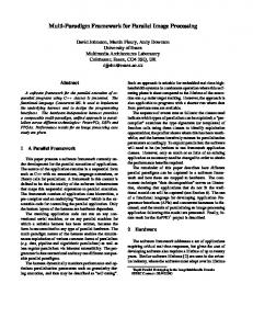
3.1. Concept of LDI Among a variety of IBR techniques, LDI is one of the most efficient rendering methods for 3-D objects with complex geometries. It represents the current scene using an array of pixels viewed from a single camera position. However, each LDI pixel contains not just color values, but also several other attribute values. It consists of color, depth between the camera and the pixel, and other attributes that support rendering of LDI. Three key characteristics of LDI are: (1) it contains multiple layers at each pixel location, (2) the distribution of pixels in the back layer is sparse, and (3) each pixel has multiple attribute values. Because of these special features, LDI enables us to render arbitrary views of the scene at new camera positions. Moreover, the rendering operation can be performed quickly with the listpriority algorithm proposed by McMillan [21]. When the rays are emanating from a reference viewpoint (an LDI camera), it is possible to store intersecting points between rays and an object. Each intersecting point contains color and depth information. Figure 1 represents the conceptual diagram of LDI [1]. As shown in Fig. 1, the first intersecting points construct the first layer of LDI, the second ones build up the second layer, and so on. Consequently, each layered depth pixel (LDP) has different number of depth pixels (DPs), which contain color, depth, and auxiliary information for reconstruction of multi-views. 3.2. Generation of LDI from Multi-view Images It is possible to generate LDI by storing intersecting points with color and depth by adopting the concept in Fig. 1, but this method can only be applied to 3-D computer graphics (CG) models. Since rays cannot go through the real object, we need another approach to generate LDI from natural images. Figure 2 shows the generation process of LDI using multiple color and depth images [1]. The LDI
90
Yoon et al. Ray A
Ray B
Ray C
Layer 1 Layer 2 Layer 3 Layer 4 LDI Camera Figure 1.
Conceptual diagram of LDI.
scene viewed from the camera C1 can be constructed by warping pixels in other camera locations, such as C2 and C3, to the camera C1 location. When the warped points, c and d, are placed in the same pixel location, their depth values are compared. If the difference between depth values is greater than a predefined threshold, a new layer is created; otherwise, the warped pixels are merged into the current layer. LDI contains several attribute data together with multiple layers at each pixel location. A single LDI pixel consists of color, depth, and auxiliary data that support reconstruction of multi-view images from the decoded LDI. Therefore, color and depth information contained in multi-view video can be properly stored in the data structure of LDI. The overall data structure of LDI is shown in Fig. 3. 3.3. Analysis of the MPEG MVC Multi-view Test Data There are various kinds of multi-view video test sequences provided by MPEG AHG on MVC [19, 22]. Several proponents provide about 20 sequences with different properties. Recently, MPEG has been issued the CfP on MVC [19] and consequently eight sequences have been selected as the test sets for the CfP on MVC. They have been selected by considering diverse features, such as the number of cameras (5, 8, and 100), camera arrangements (1-D parallel, 1-D parallel convergent, 1-D arc, 2-D cross, and 2-D array), frames per second (15, 25, and 30), image
resolutions (VGA and XVGA), scene complexity, and camera motions. Besides, all the test sequences contain camera parameters for their own camera arrangement and the validation of those camera parameters has been done in MPEG AHG on 3DAV. The properties of the selected multi-view video test sequences are summarized in Table 1 [22]. Among them, Microsoft Research (MSR) provided the multiview video sequence, BBreakdancers^ with camera parameters and depth information [12, 23]. Only one sequence contains depth information for whole frames. 3.4. Current Problems in Estimating Disparity from Test Set Without Depth Information If we are just targeting for providing viewing interactions (e.g., changing viewpoints) to users, depth information may not be essential in that case. However, if the aim is to produce visible depth impression, for example in 3DTV applications, depth information would be essential and critical. For the latter, it is very helpful to store and utilize depth data in a certain data structure, for instance, based on LDI. If we use test data sets without depth information to generate LDI, we need to estimate disparity/depth from them. Under the parallel camera arrangement, disparity can be computed by using stereo matching algorithms and depth values are obtained by calculating z ¼ bf =d, where z is the depth, b is the baseline, f is the focal length, and d is the estimated disparity. As shown in Fig. 4, we can obtain one depth map per two parallel images captured from adjacent cameras in the case of
A Framework for Representation and Processing of Multi-view Video
Figure 2.
91
Generation of LDI from multiple color and depth images.
the 1-D parallel camera configuration. We have estimated disparity and depth values for the test sequences from KDDI and MERL. Since there are eight cameras in the test set, seven depth maps are acquired for the first frame using the stereo matching algorithm. If the camera arrangement is 1-D arc or 1-D convergent, we need to rectify captured videos to set the optical axis of each video parallel. There are several problems in generating LDI frames from the test sets without depth information. Although we can easily compute depth images from disparity maps under the parallel camera arrangement, the quality of the computed depth map is not sufficient. Figure 5 presents histogram equalized depth maps acquired from the KDDI data set: Flamenco1 and Race2. As shown in Fig. 5, it is difficult to figure out depth positions of objects within the computed depth map. One of the main reasons is related to the image rectification that can correct the misalignment of parallel images. The other reason could be the accuracy of the stereo matching algorithm that we used. We exploited a kind of the real-time disparity estimation technique [24], which focuses on the fast computation rather than the accuracy of estimation. Figure 6 shows
the other results for the BExit^ sequence using a different kind of stereo algorithm. As shown in Fig. 6, it is needed to reduce noise and perform further postprocessing to improve the quality. If we use a more stable and accurate stereo matching algorithm and perform more iterations or refinements, we can obtain more reliable results. However, it is very time consuming and it requires additional pre/post processing to acquire sufficient quality of depth maps. In this sense, there are several problems in generating LDI frames from the test sets without depth information. Although we can easily compute depth images from disparity maps under the parallel camera arrangement, there is no guarantee of the accuracy of the computed depth map to be used in the generation of LDI. Because of these reasons, we are focusing on the test sequence containing depth information for whole video frames in this paper, e.g., the BBreakdancers^ sequence. It includes a sequence of 100 images captured from eight cameras; the camera arrangement is 1-D arc with about 20 cm horizontal spacing. Depth maps computed by stereo matching algorithms are provided for each camera together with the camera parameters: intrinsic parameters, barrel distortion, and rotation matrix. The exact
92
Yoon et al.
Figure 3.
Data structure of LDI.
3.5. Generation of LDIs from Natural Multi-view Video with Depth Information
depth range is also given [12, 23]. Figure 7 shows some of sample images of the BBreakdancers^ sequence. As we can observe in Fig. 7, the depth image from MSR is more reliable than the calculated ones for the Bexit^ sequence. Here, the depth image is represented with 8 bits/pixel.
Table 1.
Figure 8 presents the overall procedure for generating LDIs from the natural multi-view video, not from 3-D synthetic models.
Properties of the selected test sequences for the CfP on MVC.
Property
KDDI
MERL
FhG-HHI
Nagoya Univ.
MSR
Sequences
Flamenco2 Race1
Ballroom Exit
Uli
Rena Akko&Kayo
Resolution
VGA
VGA
XVGA
VGA
XVGA
Frame rate (fps)
30
25
25
30
15
Number of cameras
5/8
8
8
100
8
Camera arrangement
2-D cross/1-D parallel
1-D parallel
1-D parallel convergent
1-D parallel/2-D array
1-D arc
Camera parameters
A
A
A
A
A
Depth information
N/A
N/A
N/A
N/A
A
A: available, N/A: not available.
Breakdancers
A Framework for Representation and Processing of Multi-view Video
Figure 4.
Depth map extraction for 1-D parallel camera arrangements.
After obtaining depth information from the multiview video, we perform 3-D warping to generate a single LDI using multiple color and depth images. We start from the following incremental 3-D warping equation [1] because the original McMillan_s warping equation [25] is very complex and has many parameters to be computed. If we use the incremental warping equation, we can reduce the computational complexity for 3-D warping. C1 ¼ V1 � P1 � A1 ; C2 ¼ V2 � P2 � A2 ; T1;2 ¼ C2 � C�1 1
Figure 5.
93
Estimated depth map for KDDI test sequences.
ð1Þ
2
3 2 3 x2 � w 2 x1 6y 7 6y � w 7 6 17 6 2 27 T1;2 � 6 7 ¼ 6 7 4 z1 5 4 z2 � w2 5 1
w2 2
3 2 3 x1 0 6y 7 607 6 17 6 7 ¼ T1;2 � 6 7 þ z1 � T1;2 � 6 7 405 415 1
ð2Þ
0
¼ start þ z1 � depth
where V is the viewport matrix, P is the projection matrix, and A is the affine matrix.
94
Yoon et al.
Figure 6. Depth map extraction for exit sequence: a camera 0, b camera 1, c camera 2, d depth map from camera 0 and camera 1, e depth map from camera 1 and camera 2.
The camera matrix C can be easily calculated for 3-D synthetic models or scenes. While the viewport matrix is computed from the image resolution, the projection matrix is automatically determined by OpenGL according to the orthogonal/perspective view, and the affine matrix is computed from the
Figure 7.
rotation and translation matrix. However, it is difficult to estimate these three matrices in the natural video because the meanings of projection and affine matrices are not clearly defined. Because of these reasons, we use a different camera matrix calculated from the given camera
Test images from Microsoft Research, BBreakdancers:^ a 8 bits per R, G, and B channel, respectively, b 8 bits per depth.
A Framework for Representation and Processing of Multi-view Video
Test Data without Depth Info.
Test Data with Depth Info.
Natural Multi-view Video
Estimation
95
Disparity/Depth Map Extraction Given Depth
Disparity/Depth 3-D Warping
Depth Comparison/Thresholding
Layered Depth Images Figure 8.
Generation of LDIs from the natural multi-view video.
parameters of the MPEG-4 3DAV test sequences, instead of estimating each V, P, and A matrix in the natural video. The modified camera matrices and the 3-D warping equation are as follows [26]. �
�
�
�
�
�
�
�
� �1
C1 ¼ A1 � E1 ; C2 ¼ A2 � E2 ; T1;2 ¼ C2 � C1 2
�fSx
� 6 A¼ 4 0 0 2 R11 � 6 E ¼ 4 R21 R31
� �fSy 0
tx
3
7 ty 5; 1
R12
R13
R22 R32
R23 R33
ð3Þ
T1
3
ð4Þ
7 T2 5 T3
3 3 2 x1 x2 � w2 � 6 y1 7 6 y2 � w2 7 7 7 6 T1;2 � 6 ð5Þ 4 z1 5 ¼ 4 z2 � w 2 5 1 w2 2 3 2 3 x1 0 � � 607 6 y1 7 6 7 7 ¼ T1;2 � 6 4 0 5 þ z1 � T1;2 � 4 1 5 0 1 2
¼ start þ z1 � depth where fSx , fSy are the focal length, Sx, Sy are scaling factors, tx, ty are positions of the focal center, and q is
�
the skew angle. A defines the intrinsic camera � parameters and E is the Euclidean transform expressing a rotation and a translation. Finally, the camera matrix � C is changed to C , but the Eq. (5) is the modified version of Eq. (1). We should add an additional row ½�0 0 0 1� to �make a homogeneous 4�4 camera matrix � , because � becomes a 3�4 matrix. C A E After performing the 3-D warping, depth comparison and thresholding is conducted using the moved pixels, which contain color and depth information. Since the data size of generated LDI depends on this depth thresholding, we can control the experimental threshold value considering final reconstruction quality. 4.
Framework for Representation and Processing of the Multi-view Video Using LDI
4.1. Framework for Representation and Encoding of the Constructed LDI Frames Figure 9 shows the overall system diagram for representation and processing of multi-view vide using the concept of LDI [2]. As shown in Fig. 9, the first color and depth frames of the multi-view video are collected and warped to the selected LDI view. Consequently, eight color and eight depth images construct the first frame of LDI sequence. In this paper, the LDI sequence and LDI frames have the same meaning, which is the sequence of LDI. Once we obtain the LDI frames from the above procedure, the reconstruction of multiple view images can be
96
Yoon et al.
accomplished by applying the generation procedure in reverse order. Since there is information loss caused by depth thresholding in generating LDI and limited viewing ranges inherent by camera arrangements, the compensation module is required before reconstructing the multi-view images. In the encoding step, LDI data could be preprocessed [3] and H.264/AVC is applied to those processed data adaptively. One important thing to be considered in the encoding process is to exploit the special characteristics of LDI, which will be described in the next subsection. Because each layer of LDI contains empty pixels, we should fill or remove those vacant holes before applying encoding algorithms.
LDI frames. LDI pixel contains color values, depth between the camera and the pixel, and other auxiliary data that support reconstruction of multi-view images from the decoded LDI. Three key characteristics of LDI have been already described in Section 2. Because of those special features, LDI enables us to render arbitrary views of the scene at new camera positions. Table 2 lists the number of pixels included in each layer of the generated LDI. The LDI frame in Table 2 is constructed from the first eight color and depth frames of the BBreakdancers^ sequence. As we can observe from the table, pixel distribution becomes sparse as the layer number increases. It means that the data size of the original multi-view video could be reduced by converting them into the specific data structure based on LDI.
4.2. Characteristics of the Generated LDI Frames 4.3. Encoding of the LDI Frames Unlike those algorithms, our proposed framework is based on the conversion between multi-view videos and LDI frames. Before encoding the generated LDI frames, we first analyze the properties of the constructed
Figure 9.
In this paper, we have tested with two kinds of encoding algorithms. The first idea is that we need to aggregate scattered pixels into the horizontal or vertical
A framework for representation, encoding, and reconstruction of multi-view video using LDI.
A Framework for Representation and Processing of Multi-view Video
Table 2. Pixel distribution of the generated LDI (Depth threshold value: 3.0). Layer
Pixel occupation [%]
Layer
Pixel occupation [%]
1
100.0
5
46.8
2
90.4
6
34.7
3
69.8
7
29.0
4
47.0
8
19.1
fill the other layers. This increases the prediction accuracy of H.264/AVC, therefore data size could be reduced further. We can eliminate the newly filled pixels in the decoding process because information for the number of layer (NOL) is sent to the decoder. It is an eight bit gray scale image that each pixel contains an unsigned integer number representing how many layers there is. 5.
direction [10] because each layer of the constructed LDI has different number of pixels. Although H.264/ AVC is powerful to encode rectangular images, it does not support shape-adaptive encoding modes. We therefore aggregate each layer image and then fill the empty space with the last pixel value in the aggregated pixels line by line. First, the scattered pixels in each layer are pushed to the horizontal direction. Second, the locally aggregated images are merged into a single huge image and empty pixels are padded. For example, if each layer image has XVGA (1,024�768) resolution, the single aggregated image becomes 8,192�768. Finally, the generated one is divided into the images with pre-defined resolutions, e.g., 1,024�768, to employ H.264/AVC. The second method is called as layer filling. We can fill the empty pixel locations of all layer images using pixels in the first layer. Since the first layer has no empty pixels, we can use same pixels in the first layer to
97
Experiment Results and Analysis
5.1. Generation of LDIs from Natural Multi-view Video with Depth Information The main part of generating LDI frames from the natural multi-view video is the incremental 3-D warping. Figure 10 depicts the first frame at each camera location and the reference camera is camera 4. The results of the incremental 3-D warping using Eqs. (3), (4), and (5) is shown in Fig. 10. We can observe that actors are moving as the camera number changes. In order to identify the warping results clearly, we did not interpolate holes. White pixels in each image represent the holes, which are generated by the 3-D warping. In Fig. 11, camera number 4 is the reference LDI view and the warping has been performed from other camera locations to the reference LDI view. When the warping is carried out from the left cameras (camera 0, 1, 2, and 3) to
Figure 10. The first frame at each camera location: a camera 0, b camera 1, c camera 2, d camera 3, e camera 4, f camera 5, g camera 6, h camera 7.
98
Yoon et al.
Figure 11.
Results of the incremental 3-D warping: a camera 0 to camera 4, b camera 1 to camera 4, c camera 7 to camera 4.
the reference camera, major holes are created along the right side of the actors. On the other hand, holes are mainly distributed in the left side of the actors as the warping is done from the right cameras (camera 5, 6, and 7) to the LDI view. The generated LDI has several layers and the maximum number of layer is the same as the camera number. For BBreakdancer,^ each LDI frame can therefore have eight layers in maximum. The layer images (color components) of the constructed LDI frame with depth threshold 5.0 is presented in Fig. 12. As for depth components, the resultant images are similar except they are represented as 8 bit gray scale images. 5.2. Preprocessing of the LDI Frames As we described in Section 4, we have tested with two kinds of preprocessing methods. Figure 13
represents the results of the data aggregation with the horizontal direction. The first row shows each layer image of the constructed LDI with the depth threshold of 5.0. For each image, data aggregation is performed with the horizontal direction. Finally, each aggregated images are again aggregated into a single one. The third row represents the aggregated result. The other method is filling empty locations using pixel values in the first layer, which is called layer filling technique. The result of layer filling is shown in Fig. 14. 5.3. Comparison of the Data Size In Table 3, we have compared the data size between sum of frames of the test sequence and the generated LDI frame. In the table, sum of frames means the summation of eight color and depth images of the test sequence without encoding. Simulcast using
Figure 12. Layer images of the first LDI frame: a first layer, b second layer, c third layer, d fourth layer, e fifth layer, f sixth layer, g seventh layer, h eighth layer.
A Framework for Representation and Processing of Multi-view Video
Figure 13.
Results of the data aggregation with horizontal direction.
H.264/AVC (color + depth) means the summation of data size calculated by the independent coding of color and depth images. Experimental conditions are as follows. We have used JM 9.5 reference software to encode simulcast color and depth videos. The intra frame coding (I slice) was used for each color and depth frame in the case of
Figure 14.
99
Results of the layer filling.
the simulcast coding. Search range of 32 and QP of 30 were used. In addition, the same parameters were used for encoding of the LDI frame after applying data aggregation and layer filling. We have exploited two kinds of encoding methods, one is data aggregation with horizontal direction and the other is the layer filling. Based on the reconstruction
100
Table 3.
Yoon et al.
Data size for the BBreakdancers^ sequence. First eight frames
Sum of frames (color + depth) [kB] Simulcast using H.264/AVC (color + depth) [kB] Simulcast using H.264/AVC (color only) [kB] LDI frame generated from 16 images [kB] (Threshold=0.0, bit allocation for depth=8 bits) Encoded LDI frame using the data aggregation (with the horizontal direction) [kB] Encoded LDI frame using layer filling [kB] LDI frame generated from 16 images [kbytes] (Threshold=3.0, bit allocation for depth=8 bits) Encoded LDI frame using the data aggregation (with the horizontal direction) [kB] Encoded LDI frame using layer filling [kB]
Second eight frames
25,166.0
25,166.0
137.7
132.5
97.4
96.3
24,520.0
24,644.0
135.4
133.7
71.4
72.9
13,924.0
13,803.0
131.7
133.8
48.4
48.2
13,808.0
13,723.0
Encoded LDI frame using the data aggregation (with the horizontal direction) [kB]
91.7
93.0
Encoded LDI frame using layer filling [kB]
46.3
47.0
LDI frame generated from 16 images [kbytes] (Threshold=5.0, bit allocation for depth=8 bits)
results, we can determine the threshold, how much we can allow the difference among depth values. Table 3 shows the data size by changing the depth threshold value from 0.0 to 5.0, but the data size has not decreased much as the threshold value is over 3.0 from the experiments. The depth threshold means the difference among actual depth values. For the BBreakdancers^ sequence, the given depth range is from 44.0 to 120.0. Table 3 does not list the data size of residual information. The residual information mainly depends on the distance among cameras and the actual viewing range. In our experiments, the size of residual data has changed based on the depth thresholding. For the residual data, we calculate the difference between the original images and the reconstructed ones, and then encode the difference images. Moreover, the NOL data size should be added to calculate the final data size; the NOL image is lossless coded by H.264/AVC intra mode with the fixed quantization parameter. There are several issues to be considered in the future experiments. First, the relationship between the number of layers and the quality of reconstructed multi-views should be analyzed carefully. Second, shape adaptive transforms, such as a shape-adaptive discrete cosine transform (SA-DCT) and a shapeadaptive discrete wavelet transform (SA-DWT), could be used to encode LDI data because H.264/ AVC supports only the 4�4 integer transform. Finally, we will conduct temporal prediction of constructed LDI frames to find more appropriate
methods to encode LDI sequence using more test sequences with depth information. Because the performance comparison results in terms of PSNR vs. bitrates require the rate allocation for each LDI frame, it would be given after performing the temporal prediction of LDIs.
6.
Conclusion
In this paper, we have described the details of a framework for representation and processing of multi-view video data using the concept of layered depth image (LDI). If we want to provide visible depth impression or immersion to users, 3-D information like depth contained in multi-view video is very important. That is the reason why we have tried to utilize that information in the proposed framework. From the experimental results, the proposed representation shows better performance than the simulcast coding method in terms of data size. It is difficult to directly compare the proposed method with other multi-view video coding algorithms dealing with only color information because our LDIbased representation contains all the information such as color, depth, and other auxiliary data. However, we have observed that our framework can efficiently treat multiple videos in the same space and reduced data to manageable size. We therefore believe that the proposed approach could be helpful to represent, and process multi-view video data effectively.
A Framework for Representation and Processing of Multi-view Video
Acknowledgement This research was supported by MIC under the ITRC support program supervised by IITA through Realistic Broadcasting Research Center (RBRC) at Gwangju Institute of Science and Technology (GIST).
References 1. J. Shade, S.J. Gortler, L.W. He, and R. Szeliski, BLayered Depth Images,^ in Proc. ACM SIGGRAPH, 1998, pp. 231– 242. 2. S.U. Yoon, S.Y. Kim, E.K. Lee, and Y.S. Ho, BA Framework for Multi-view Video Coding Using Layered Depth Images,^ Lect. Notes Comput. Sci. (LNCS), vol. 3767, 2005, pp. 431–442. 3. S.U. Yoon, S.Y. Kim, and Y.S. Ho, BPreprocessing of Depth and Color Information for Layered Depth Image Coding,^ Lect. Notes Comput. Sci. (LNCS), vol. 3333, 2004, pp. 622–699. 4. H. Shum, S.B. Kang, BA Review of Image-based Rendering Techniques,^ in IEEE/SPIE Vis. Commun. Image Process (VCIP), June (2000), pp. 2–13. 5. H. Shum, S.B. Kang, and S. Chan, BSurvey of Image-based Representations and Compression Techniques,^ IEEE Trans. Circuits Syst Video Technol., vol. 13, no. 11, 2003, pp. 1020– 1037. (November) 6. C.F. Chang, G. Bishop, and A. Lastra, BLDI tree: A Hierarchical Representation for Image-based Rendering,^ in Proc. SIGGRAPH, 1999, pp. 291–298. 7. R. Namboori, H.C. Teh, and Z. Huang, BAn Adaptive Sampling Method for Layered Depth Image,^ in Proc. Computer Graphics International, 2004, pp. 206–213. 8. J. Shade, M.F. Cohen, and D.P. Mitchell, BTiling Layered Depth Images,^ Technical Report, Univ. of Washington, 2000. 9. H. Kim, S. Kim, B. Koo, and B. Choi, BLayered Depth Image Using Pixel Grouping,^ in Proc. Visual Systems and Multimedia (VSMM), 2001, pp. 121–127. (October) 10. J. Duan and J. Li, BCompression of the LDI,^ IEEE Trans. Image Process., vol. 12, no. 3, 2003, pp. 365–372. 11. Y.H. Im, C.Y. Han, and L.S. Kim, BA Method to Generate Soft Shadows Using Layered Depth Image and Warping,^ IEEE Trans. Vis. Comput. Graph., vol. 11, no. 3, 2005, pp. 265–272. (May/June) 12. C.L. Zitnick, S.B. Kang, M. Uyttendaele, S. Winder, and R. Szeliski, BHigh-quality Video View Interpolation Using a Layered Representation,^ in Proc. ACM SIGGRAPH, 2004, pp. 600–608. 13. T. Kanade, P.W. Rander, and P.J. Narayanan, BVirtualized Reality: Constructing Virtual Worlds from Real Scenes,^ MultiMedia Mag., vol. 1, no. 1, 1997, pp. 34–47. 14. W. Matusik, C. Buehler, L. McMillan, and S.J. Gortler, BImage-based Visual Hulls,^ in Proc. of ACM SIGGRAPH, 2000, pp. 369–374.
101
15. C. Carranza, C. Theobalt, M.A. Magnor, and H.-P. Seidel, BFree-viewpoint Video of Human Actors,^ ACM Trans. Graph., vol. 22, no. 3, 2003, pp. 569–577. 16. J.C. Yang, M. Everett, C. Buehler, and L. McMillan, BA Realtime Distributed Light Field Camera,^ in Eurographics Workshop on Graphics, 2002, pp. 77–85. 17. ISO/IEC JTC1/SC29/WG11 N6720, BCall for Evidence on Multi-view Video Coding,^ 2004. 18. ISO/IEC JTC1/SC29/WG11 N6999, BReport of the Subjective Quality Evaluation for Multi-view Coding CfE,^ 2005. 19. ISO/IEC JTC1/SC29/WG11 N7327, BCall for Proposals on Multi-view Video Coding,^ 2005. 20. ISO/IEC JTC1/SC29/WG11 N7779, BSubjective Test Results for the CfP on Multi-view Video Coding,^ 2006. 21. L. McMillan, BA List-priority Rendering Algorithm for Redisplaying Projected Surfaces,^ UNC Technical Report TR95-005, University of North Carolina, 1995. 22. ISO/IEC JTC1/SC29/WG11 N7567, BUpdated Call for Proposals on Multi-view Video Coding,^ 2005. 23. Interactive Visual Media Group at Microsoft Research, http:// research.microsoft.com/vision/InteractiveVisualMediaGroup/ 3DVideoDownload/. 24. BA Study on Real-time Extraction of Depth and Disparity Map for Multi-viewpoint Images,^ in ETRI Research Report, 2002. (November) 25. L. McMillan, BAn Image-based Approach to Three-dimensional Computer Graphics,^ Ph.D. Dissertation, University of North Carolina at Chapel Hill, 1997. 26. S.U. Yoon, E.K. Lee, S.Y. Kim, Y.S. Ho, K. Yun, S. Cho, and N. Hur, BInter-camera Coding of Multi-view Video Using Layered Depth Image Representation,^ Lect. Notes Comput. Sci. (LNCS), vol. 4261, 2006, pp. 432-441.
Seung-Uk Yoon received a B.S. degree in electronic engineering from Sogang University, Seoul, Korea in 2000 and M.S. degree in Information and Communications Engineering from Gwangju Institute of Science and Technology (GIST), Gwangju, Korea in 2002. He is currently working toward a Ph.D. degree in the Information and Communications Department of GIST. His research interests include multi-view video coding algorithms and systems, layered depth image compres-
102
Yoon et al.
sion, image-based rendering, immersive media processing, and 3-D scene representation.
Eun-Kyung Lee received both B.S. and M.S. degree in computer engineering from Honam University, Korea in 2002 and 2004, respectively. She is currently working towards her Ph.D. degree in the Information and Communications Department of Gwangju Institute of Science and Technology (GIST), Korea. Her research interests include multi-view video coding algorithms and systems, light field compression, image-based rendering, 3-D scene representation, and realistic broadcasting.
Sung-Yeol Kim received his B.S. degree in Information and Telecommunication engineering from Kangwon National
University, Korea in 2001 and M.S. degree in Information and Communication Engineering at the Gwangju Institute of Science and Technology (GIST), Korea in 2003. He is currently working towards his Ph.D. degree in the Information and Communications Department of GIST, Korea. His research interests include digital signal processing, video coding, 3-D mesh representation, 3-D mesh compression, 3-D television, and realistic broadcasting.
Yo-Sung Ho received both B.S. and M.S. degrees in electronic engineering from Seoul National University, Korea in 1981 and 1983, respectively, and a Ph.D. degree in Electrical and Computer Engineering from the University of California, Santa Barbara in 1990. He joined the Electronics and Telecommunications Research Institute (ETRI), Korea in 1983. From 1990 to 1993, he was with Philips Laboratories, Briarcliff Manor, New York, where he was involved in development of the advanced digital highdefinition television (AD-HDTV) system. In 1993, he rejoined the technical staff of ETRI and was involved in development of the Korea direct broadcast satellite (DBS) digital television and high-definition television systems. Since 1995, he has been with the Gwangju Institute of Science and Technology (GIST), where he is currently a professor in the Information and Communications Department. His research interests include digital image and video coding, image analysis and image restoration, advanced coding techniques, digital video and audio broadcasting, 3-D television, and realistic broadcasting.