Electronic Notes in Theoretical Computer Science 116 (2005) 31–44 www.elsevier.com/locate/entcs
A Framework for the Integration of Functional and Non-functional Analysis of Software Architectures V. Cortellessa, A. Di Marco, P. Inverardi F. Mancinelli, P. Pelliccione 1 ,2 Dipartimento di Informatica Universit` a di L’Aquila Via Vetoio 1, 67010 Coppito (AQ), Italy
Abstract The separation of functional and non-functional analysis of software systems often prevents from considering design solutions that would be evident if an integrated analysis would be possible. Lack of analysis integration is in fact leading software developers to loose precious feedback that would improve the quality of the software product or, even better, would avoid late software inconsistencies with respect to functional or non-functional requirements. In this paper we introduce a framework for software analysis integration. The framework core is XML-based and consists of software models and formal relations among models. The relations help to automatically propagate the analysis feedback among software models. We specify how different analysis methodologies can be integrated in our framework. We also show how the Eclipse platform represents a natural implementation environment for such a framework. Keywords: Functional analysis, non-functional analysis, XML Schema.
1
Introduction
Software analysis has always been a non-trivial activity along the software development process, due both to special skills required to developers and to short time-to-market. On the other end, as the software systems progress 1
This work has been partially supported by CNR “Progetto Societ` a dell’Informazione SP4”. 2 Email:
[email protected] 1571-0661/$ – see front matter © 2004 Elsevier B.V. All rights reserved. doi:10.1016/j.entcs.2004.02.088
32
V. Cortellessa et al. / Electronic Notes in Theoretical Computer Science 116 (2005) 31–44
and find new application environments (e.g. heterogeneous platforms, mobile devices, etc.) the analysis of functional and non-functional properties is becoming a primary concern to meet customer requirements. Major efforts have been spent in the past for the functional analysis of software systems, that brought nowadays to offer quite sophisticated (formal and semiformal) methodologies and tools to verify and validate the functional behaviour of a software system since the early phases of its lifecycle [1]. On the contrary, non-functional attributes (such as performance, security, etc.) have not received the same consideration. Only in the last few years the idea of integrating such type of analysis along the whole software lifecycle has been supported from new methodologies aimed at filling the gap between the software development process and its non-functional validation [2]. The rationale behind this paper is that the software evolution seems to ask for advances in two major topics of software analysis: (i) the integration of functional and non-functional analysis, and (ii) the automation in embedding the feedback resulting from analysis into the software models. The need of integration has been repeatedly claimed in the recent past, with particular focus on the software architectural level [3]. We introduce here a framework to cope with the integration issues at that level. We started from the goal of evidencing inter-relationships between functional and non-functional aspects that would not necessarily emerge from separate analysis. For example, it is intuitive that upon detecting a deadlock in a software model, a critical component may be split in two components, and this refinement may heavily affect the software performance. Viceversa, a security analysis may lead to introduce additional logics to components (that work as firewalls) in a subsystem, thus the behaviour of the subsystem needs to be validated again. In many cases analysis methodologies are based on a translation of the software model into a different notation to be analyzed (e.g., a formal language for functional verification, or a Petri Net for performance validation). Our intent is to place an intermediate representation (based on XML) of software models that may work as a common ground to apply functional and non-functional analysis as well as to feed back the analysis results on the software models. As a short term goal, in this paper we integrate two existing methodologies for software analysis: Charmy [11,12] that translates scenarios and state machine diagrams into Promela language [4] for software formal verification, and a methodology that generates a Markov model [5] from a software specification based on the Æmilia architectural description language [6], to validate software performance. Both the methodologies work at an architectural level. Our long term goal is to incrementally implement such framework by embedding other methodologies for software analysis at the architectural level.
V. Cortellessa et al. / Electronic Notes in Theoretical Computer Science 116 (2005) 31–44
33
Obviously this goal lays on the ability of the XML core to be extended. As we will show in Section 3, we devise this ability as the result of two tasks: keeping the XML core general enough to embed new software notations; introducing rules and relationships across different software notations that allow to automatically propagate an analysis feedback from a functional world to a non-functional one, and viceversa. The framework implementation will be based on the Eclipse platform, namely a software tool for tool implementation. This is a relevant aspect of our work, in that by embedding structures, rules and algorithms into Eclipse, we exploit the well-known integration features of this technology. Loosely related work to this paper can be found in the research done in the field of independent verification and validation of software systems (e.g., see [7]). This paper contributes to the integration of software analysis by proposing the design (as well as an idea of implementation) of an actual integration framework. A similar approach can be found in [8], where a framework has been introduced to integrate non-functional requirements in conceptual models. The integration work in [8] is performed at a requirement elicitation level, and is based on Entity-Relationship models. Our approach differs from the one in [8] because we assume that the (functional as well as non-functional) requirements have been formulated and modeled in some software notation. Then, we do not constrain the developers to build ad-hoc models (such as ER), rather our integration is based on XML models that can be automatically generated from the software models. The paper is organized as follows: in Section 2 we briefly introduce the methodologies for software analysis that we consider, in Section 3 our framework is described, along with details and examples on the XML core and the rules across notations, in Section 4 we introduce the Eclipse tool and show how it suitably fits to the implementation of our framework.
2
Software analysis methodologies
2.1 Charmy (CHecking ARchitectural Model consistencY) Charmy
is a framework that, since from the earlier stage of the software development process, aims to assist the software architect in designing software architectures and in validating them against functional requirements. State machines and scenarios are used as the source notation for specifying software architectures and their behavioral properties. Model checking techniques, and in particular the model checker SPIN [4], are used to check the consistency between the software architecture and the functional requirements by using a Promela specification and B¨ uchi Automata [9] which are both derived from
34
V. Cortellessa et al. / Electronic Notes in Theoretical Computer Science 116 (2005) 31–44
the source notations. The former is the SPIN modeling language, while the latter is the automata representation for Linear-time Temporal Logic (LTL) formulae [10] that expresses behavioral properties. Charmy currently offers a graphical user interface which aids the software architecture design and automates the machinery of the approach. Technical details on Charmy may be found in [11,12], and an approach to integrate Charmy into a real software development life-cycle can be found in [11,12,13].
2.2 TwoTowers: Æmilia to Markov models The TwoTowers (3.0) tool [14] allows the validation of performance requirements at the software architecture level. It takes as input an Æmilia textual description, builds the corresponding Markov model (which can be both a Continuous and a Discrete Markov Chain) and evaluates the performance indices of interest. Æmilia is an architectural description language (ADL) based on the Stochastic Process Algebra EMP Agr [15]. It was introduced by Bernardo et al. in [6] with the aim of making the Stochastic Process Algebra a more familiar software model notation to software engineers. Stochastic Process Algebras (SPA) permit to analyze the performance of concurrent systems which are described as collections of entities, or processes, executing atomic actions. The processes are used to describe concurrent behaviors and they synchronize in order to communicate. Temporal information is added to actions by means of continuous random variables, representing activity durations. The quantitative analysis of the modelled system can be performed by constructing the underlying stochastic process. In particular, when action durations are represented by exponential random variables, the underlying stochastic process yields a Markov Chain. A model description in Æmilia represents an Architectural Type (AT) defined as a function of its Architectural Element Types (AET) and its architectural topology. An AET is defined by its behavior, specified either as a family of EMP Agr sequential terms or through an invocation of a previously defined AT, and by its interactions, specified as a set of EMP Agr action types occurring in the behavior. The architectural topology is specified through the declaration of a set of Architectural Element Instances (AEI) and a set of Directed Architectural Attachments (DAA) among the interactions of the AEI. Depending on the SA configuration to be specified by means of Æmilia, it can be necessary one or more AEI for each AET.
V. Cortellessa et al. / Electronic Notes in Theoretical Computer Science 116 (2005) 31–44
3
35
A framework for software analysis integration
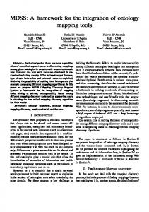
In Figure 1 we show the architecture of our framework for the integration of functional and non-functional analysis of software architectures. UML
MSC
ADLi
ADLj
Other
Input filters XML
XML Models Representation
Semantic Relations
Visual Editors
Integration Core
XML Analysis filters
filters filters
Feedback
Charmy notation
Feedback
TwoTowers notation
Feedback
Charmy
TwoTowers
Other
SPIN
QN solver
Other
Fig. 1. Our framework architecture.
Rounded boxes on the top side of the figure represents software notations adopted for the software development (e.g., the Unified Modeling Language or whatever Architectural Description Language). Let us assume that a software architecture has been built using one of these notations. Several methodologies are nowadays available to take as input a software model and to produce the same model in a different notation, ready to be validated by automated tools with respect to either functional or non-functional properties. On the bottom side of Figure 1 are presented some examples of methodologies (i.e. Charmy and TwoTowers) as square boxes, and some examples of automated tools for software analysis (e.g., the SPIN model checker). In the scenario of a stand-alone analysis of a software architecture, the sequence of steps to validate the architecture, for example from a functional viewpoint with the Charmy approach, would be as follows: the UML diagrams of the software model from the rounded box directly flow to the Charmy square box, where they are translated into the SPIN specification language (i.e., Promela) and forwarded to the SPIN model checker (a square box in the bottom side of Figure 1). SPIN runs the model and produces results that have to be examined by the developer in order to embed the analysis feedback into the software architecture.
36
V. Cortellessa et al. / Electronic Notes in Theoretical Computer Science 116 (2005) 31–44
In our framework the validation steps are different, due to the integration of such activity with other potential software analysis as well as to a certain automation in the interpretation and provision of result feedback. In Figure 1 a big square box has been placed between the topmost software notations and the bottommost analysis methodologies. It contains some filters and the XML Integration Core, which is the main component of our framework. Each Input filter translates the software model from its original notation to a XML-based common representation, namely the XML Models Representation box in Figure 1. An appropriate Analysis filter translates the XML representation into the input notation to the desired analysis methodology (e.g., Charmy notation in Figure 1). The latter notation obviously depends on the methodology, and it can go from a subset of the XML representation to a completely different language defined within the methodology. From this point on the steps are the same as for a stand-alone analysis, up to obtain results from the automated tool. The feedback resulting from a specific analysis (e.g., splitting a component upon a deadlock detection) propagates, through an Analysis filter, up to the XML Integration Core where the model is either updated or a hint is given on how to modify it. In the Semantic Relations box the rules that link entities to entities are expressed (in XML) and allow to transfer analysis feedback from a notation to another. In fact, the model changes inferred by the analysis results in the XML Integration Core, have to be reflected in the other analysis methodologies. This is the way we conceive analysis integration. In the Visual Editors box on the right side of Figure 1 there can be any editor able to take a XML representation of a software model and display it. In practice, this is an additional graphical capability of our framework that may extend analysis tools with graphical user interfaces providing either a way to interact with the software models or a way to operate with the analysis methodology tools. In the next subsection we give some details of the XML Integration Core and how it works for analysis integration.
3.1 Architecture of the XML Integration Core The Integration Core purpose is twofold. It contains an easy and manageable representation of all the notations taken in input from the considered analysis approaches by means of a common language (XML). It allows the integration of the analysis in terms of the analysis results and the produced feedbacks at the software architecture level.
V. Cortellessa et al. / Electronic Notes in Theoretical Computer Science 116 (2005) 31–44
37
To reach this last aim we introduce the concept of semantic relations among the entities of the considered notations. Semantic relations are built every time it is possible to semantically relate the concepts in different notations. This means that, in general, there is not necessarily a relation between every pair of entities of two different notations; sometimes, those relations could not exist at all. The semantic relation between two elements of two different notations strongly depends from the used approaches. This implies that the semantic relations are given by considering the approaches pairwise. We define the structure rules specifying the relations between concepts of the considered notations. Of course, when a particular software system is analyzed, these structure rules have to be instantiated on it. The rules instantiation is performed by a dedicated engine containing the needed logic to do so. We point out that an engine has to be built for each pair of approaches. SM.xsd
Scenario.xsd Aemilia.xsd
Notation Schemas (.xsd)
Engine_AEm_ Charmy Rules (.xml)
engine engine engine engine Rules(.xml) (.xml) engine Rules Rules (.xml)
Models (.xml)
Rules (.xml) (.xml) Rules
XML Models Representation
Rule Instances (.xml)
Semantic Relations
Integration Core
SetAEmilia.xml SetSM.xml SetScenario.xml
Set_AEm_Charmy_rules.xml
< bid_rule rule_elem1 ="SA/Components/StateMachine@name " rule_elem2 ="ArchiType/archiElemTypes/elementType/behavior/ process/@name "/> < condition ="pathState=pathProcess "/> . . .
Fig. 2. Structure of the Integration Core
From the previous considerations, we split the Integration Core into the XML Models Representation and the Semantic Relations as shown in Figure 2. Given an analysis approach to be integrated it is necessary to provide an XML schema for each notation taken in input. A schema describes how to produce the XML representation of the software architecture under analysis. The schemas are stored in the Notation Schemas repository (see Figure 2) while the Models repository contains the software architecture description of the system, represented in XML. For example, let us consider the Charmy and TwoTowers approaches, and a Set-Counter application which will be introduced later. The schemas of the State Machines, Scenarios and Æmilia notation (in Figure 2, SM.xsd, Scenario.xsd and Æmilia.xsd, respectively) are stored in the Notation Schemas repository. The Models repository contains the XML version of the State Machines, the Scenarios and the Æmilia textual description modeling the Set-Counter application (in the Figure 2, SetSM.xml, SetScenario.xml and SetÆmilia.xml, respectively).
38
V. Cortellessa et al. / Electronic Notes in Theoretical Computer Science 116 (2005) 31–44
Semantic Relations, instead, contains, for each pair of approaches, a set of structural rules which define relationship classes (in Figure 2 Rules (.xml)), an engine which instantiate the relationships defined by the structural rules on the current architecture. The instantiated relationships are stored within this component (in Figure 2 Rule Instances (.xml)). The engine role is to instantiate the structure rules for a particular software architecture of the system that we want to analyze. In Figure 2 we show some structure rules for Charmy and TwoTowers approaches. In particular we show two rules: the first states that there exist a semantic relation between the Charmy state machine model and the Æmilia process; the second one claims that a transition over a State Machine is related to a rated action of an Æmilia process if they belong to the same execution trace. The relation defined by the rules are specified by using XPath expression [16] over the notation schema. In this way we are able to unambiguously relate the notation elements. 3.2 Current status of the framework implementation We devise an incremental approach to the framework implementation. The analysis approaches are considered pairwise, and for each pair we intend to introduce only the missing schemas and rules needed to integrate the approach into the framework. Therefore the Notation Schemas repository as well as the XML Rules may be extended every time two approaches have to be related. Currently we have implemented (input and analysis) filters, XML schemas, rules and engine for Charmy and TwoTowers approaches. We found the XML characteristics fairly suitable for such project, and we are nowadays working on integrating other approaches (e.g., the PRIMA-UML approach for Queueing Network-based performance analysis from UML diagrams [17]). Although some similarities can be found, we remark that our integration task differs from the UML 2 project [18] because we do not intend to push software developers to use a specific notation (such as UML), rather we want to provide tools to make the software analysis as much transparent as possible to the software development process. We figure out developers not necessarily being constrained to a specific notation, and only if (and when) the need of an integrated software analysis comes up during the software lifecycle they can consider to enter the framework by providing the necessary filters, schemas and rules. We share with the UML 2 project the idea of having an XML intermediate format as a basis for the analysis tasks. Indeed, since the XMI standards for UML 2 are not yet out up to this date, it has been and it is being our concern to make our XML schemas as much compliant as possible to the XMI
V. Cortellessa et al. / Electronic Notes in Theoretical Computer Science 116 (2005) 31–44
39
standards for UML 1.x. However, even UML 2 is not wide enough to embed formal notations such as Process Algebras which are widely used, for example, in performance analysis. Therefore we try to work towards an integration framework that embeds UML as a software development notation (see Figure 1), relations among UML entities as rules already embedded into the notation and, in addition, provides tools to integrate whatever analysis approach. In practice, our rules work at the metamodel level, as they relate notation concepts to notation concepts. The need of rules to integrate software analysis is supported from a recent OMG call for proposals [19]. 3.3 Set-Counter Application To illustrate details on the Models and Rule Instances repositories, we use a simple example introduced in [20]. The application is made of two components: a Set and a Counter. If a User adds or removes an element to/from the Set (insert(e) and delete(e) respectively) the Set increments or decrements (inc and dec respectively) the number of stored elements into the Counter component. In the following, we refer to the Set-Counter architecture containing one User instance, one Set instance and one Counter instance ( 3 ). In Figure 3 we report the Charmy State Machines and the Æmilia specification for the Set-Counter application (Figure 3.b and 3.c, respectively) and a sketch of the XML representations for the User component (Figure 3.a and 3.d). These representations are built by using the appropriate input filters (interested reader can found details in [21]). A fragment of the rules instances expressing the semantic relations between the Charmy and TwoTowers approaches is shown in Figure 4. At the rightmost side of the figure, you can find the rule instance that realizes the relation between the insert transition in the User State Machine and the insert rated action of the User process inside the Æmilia description. Both these rule members are identified by means of the XPath expressions specifying their positions in the XML representations.
4
The Eclipse platform: A framework to build software tools
The Eclipse platform is an Integrated Development Environment (IDE) for anything and nothing in particular [22]. Eclipse is a framework for building integrated development environments for creating applications, and its main 3
For lack of space, we ask the reader to refer to [21] for details about the schemas and the XML files for the Set-Counter application
40
V. Cortellessa et al. / Electronic Notes in Theoretical Computer Science 116 (2005) 31–44
?insert(e)
S2
ARCHI_TYPE SET_ARCHI(void;rate a1 := 2, rate a2 := 1) ARCHI_ELEM_TYPES
?delete(e)
!dec
S0
!inc
Set S1
!insert(e) !delete(e)
ELEM_TYPE SET_Type(void;rate a2) BEHAVIOR SET(void; void) = choice{ ..SET(), ..SET() } INPUT_INTERACTIONS AND insert; delete OUTPUT_INTERACTIONS UNI inc; dec ELEM_TYPE USER_Type(void; rate a1) BEHAVIOR USER(void; void)=choice{ .USER(), .USER() } INPUT_INTERACTIONS OUTPUT_INTERACTIONS UNI insert; delete ELEM_TYPE COUNTER_Type(void; void) BEHAVIOR COUNTER(void; void)=choice{ .COUNTER(), .COUNTER() } INPUT_INTERACTIONS UNI inc; dec OUTPUT_INTERACTIONS
S0
User
ARCHI_TOPOLOGY ARCHI_ELEM_INSTANCES User: USER_Type(;a1); Set: SET_Type(;a2); Counter: Counter_Type(;);
?inc
ARCHI_INTERACTIONS
?dec
ARCHI_ATTACHMENTS FROM User.insert TO Set.insert; FROM User.delete TO Set.delete; FROM Set.inc TO Set.inc; FROM Set.dec TO Set.dec;
S0
(a) XML for User State Machine in SetSM.xml
Counter
END
(b) State Machines
(c) AEmilia Model
(d) XML for User Element Type of AEmilia specification in SetAEmilia.xml
Fig. 3. Architecture of Set-Counter Application
. . . . . . . . . < choice > . . . . . . . . . . . . SetAEmilia.xml
. . . . . .
Set_AEm_Charmy_rules.xml
Fig. 4. Rules Instance for the Set-Counter Application in TwoTowers-Charmy Integration
V. Cortellessa et al. / Electronic Notes in Theoretical Computer Science 116 (2005) 31–44
41
role is to provide mechanisms and rules to create seamlessly integrated development tools, and more. The Eclipse platform supports the construction of tools from an unrestricted variety of tool providers, and facilitates the integration of such tools, that usually manipulate different content types, and are developed by different providers. The Eclipse platform architecture is shown in Figure 5(a) and is made of the following components: i) Platform runtime: Provides all the low level Application Programming Interfaces (API) to the functionalities of the platform, which can be used by tool providers. ii) Workspace: Provides a consistent and efficient way to organize the data used by the tools deployed in the platform. iii) Workbench: Enables the tool provider to display a graphical view of the data stored in the workspace, and to provide a graphical user interface to interact with the installed tools. iv) Help, Team: Provides an integrated help system and the team working capabilities for sharing the data in the workspace between multiple users.
(a) The Eclipse platform architecture
(b) The integration framework over Eclipse
Fig. 5.
4.1 Designing the integration architecture in Eclipse The framework described in Section 3 maps very well to the Eclipse platform, which can be used to profitably implement most of the components of such a framework as extensions to the platform itself, by means of plugins. As regard to the framework architecture depicted in Figure 5(b), we give an outline of how the architectural components can be implemented using the Eclipse framework: •
Integration Core: It can be directly mapped to the Eclipse platform workspace, where all the data used by the tools deployed in the platform are saved. Since XML is the target language for storing information about the struc-
42
V. Cortellessa et al. / Electronic Notes in Theoretical Computer Science 116 (2005) 31–44
tures represented by models in the Integration Core, the Eclipse platform runtime API may be profitably used to handle such information. In fact the whole Eclipse platform relies on XML for handling data files and, as a consequence, it provides a complete support for XML processing. •
Visual Editors: The workbench, with its graphical capabilities and widget toolkits, may be used to export graphical representation of the integration core, in order to spot model sections which need to be revised (as a consequence of some analysis) or even to provide a visual way to act directly on the model by changing it. Analysis methodologies which lacks of visual tool, may also take advantage of the workbench in order to provide visual editors that can give a methodology-oriented view of the models they require. Methodologies which already have their set of modeling tools, may provide visual editors which expose a sort of control panel for those tools. In this way, external tools can be used as before, but in a more integrated way, from a single environment.
•
Input and analysis filters: These filters may be implemented as plugins which interact directly with the integration core, modifying it as needed. Notification mechanisms provided by the Eclipse platform may be also used for triggering some application logic which acts on the integration core as a consequence of an input filter importing of new models, or an analysis filter feedback which modifies the model itself (directly or indirectly).
As a side effect, all the previously cited architectural components, may take advantage of the other Eclipse framework components, especially from the team working capabilities which enables the versioning of the data stored in the workspace, and therefore in the integration core; this could be useful for keeping track of the changes made to the models and, in case, provide an effective way to rollback such changes. It is also important to point out that many companies are developing modeling tools using the Eclipse framework. Notably UML modeling tools [23] are already available and can be readily used also in the context of our integration framework. Moreover, the fact that development environments for Java and C++ have already been integrated with the Eclipse framework may be useful for bridging the gap between the models and code, for example by automatically generating skeleton code from the models stored in the integration core.
V. Cortellessa et al. / Electronic Notes in Theoretical Computer Science 116 (2005) 31–44
5
43
Conclusions
In this paper we have introduced a framework to support the integration of functional and non-functional analysis of software systems at architectural level. This work originates from the activities in our software engineering lab, where we experienced the crucial need of merging results from different software analysis approaches in order to better refine software architectures. Our framework lays on an XML-based integration core, where software models and semantic relations between the models are represented. The aim is to provide a seamless integration of different analysis methodologies. To this regard we have sketched guidelines to allow embedding new methodologies in our framework. We have also shown how such a framework can be implemented using the Eclipse platform. The scope of this paper has been limited to the integration of two methodologies, and the XML models as well as the semantic rules that we have instantiated promisingly support our basic ideas. Our main research direction obviously leads to embed new methodologies for analysis at architectural level in our framework. This task shall bring to enlarge the integration core in terms of software model representations as well as semantic relations. If future results in this direction will appear as promising as the ones obtained from this first setting, a long-term goal will be to extend the scope of the framework to other software lifecycle phases.
References [1] Proc. of SPIN workshops. 1995-today. [2] Proc. of ACM Workshop on Software and Performance, 1998, 2000, 2002, 2004. [3] A.H. Dutoit, D. Kerkow, B. Paech, and A. von Knethen. Functional requirements, nonfunctional requirements, and architecture should not be separated. Int. Workshop REFSQ ’02, Essen, September 2002. [4] G. J. Holzmann. ”The SPIN Model Checker: Primer and Reference Manual”. Addison-Wesley, September 2003. [5] H. C. Tijms. ”Stochastic Models, An Algorithmic Approach”. John Wiley and Sons Ltd, 1994. [6] M. Bernardo, P. Ciancarini, and L. Donatiello. Stochastic Process Algebra: From an Algebraic Formalism to an Architectural Description Language. In Performance Evaluation of Complex Systems: Techniques and Tools, M.C. Calzarossa and S. Tucci editors, LNCS, number 2459 (2002), pages 236–260, Rome(Italy). [7] E. Dalrymple and M. Edwards. Independent integrated verification and validation. January 2003. [8] L.M. Cysneiros, J. de Melo Sabat Neto, and G.C. Sampaio do Prado Leite. A framework for integrating non-functional requirements into conceptual models. Requirements Engineering, 6 (2001), 2001 Springer-Verlag.
44
V. Cortellessa et al. / Electronic Notes in Theoretical Computer Science 116 (2005) 31–44
[9] R. Buchi, J. On a decision method in restricted second order arithmetic. In Proc. of the International Congress of Logic, Methodology and Philosophy of Science, pages 1–11. Standford University Press, 1960. [10] A. Pnueli. The temporal logic of programs. In Proc. 18th IEEE Symposium on Foundation of Computer Science, pages 46–57, 1977. [11] P. Inverardi, H. Muccini, and P. Pelliccione. Automated check of architectural models consistency using SPIN. Automated Software Engineering Conference Proceedings (ASE 2001), San Diego, California, November 2001. [12] P. Inverardi, H. Muccini, and P. Pelliccione. Technical report. [13] D. Compare, P. Inverardi, P. Pelliccione, and A. Sebastiani. Integrating model-checking architectural analysis and validation in a real software life-cycle. In Proc. 12th Formal Methods 2003, European Symposium (FM03), Lecture Notes in Computer Science, n. 2805 (2003). Springer, September 2003. [14] M. Bernardo. Twotowers 3.0: Enhancing usability. In Proceedings of the 11th IEEE/ACM Int. Symp. on Modeling, Analysis and Simulation of Computer and Telecomunication Systems (MASCOTS 2003), pages pp.188–193, Orlando (FL), 2003. [15] M. Bernardo and M. Bravetti. Performance Measure Sensitive Congruences for Markovian Process Algebras. Theoretical Computer Science, 290, (2003):117–160. [16] Xml path language (xpath) version 1.0. w3c recommendation 16 november 1999. http://www.w3c.org/TR/xpath. [17] V. Cortellessa and R. Mirandola. PRIMA-UML: a performance validation incremental methodology on early UML diagrams. Science of Computer Programming, 44 (2002), July 2002, Elsevier Science. [18] Uml 2.0 superstructure specification. omg http://www.omg.org/docs/ptc/03-08-02.pdf.
adopted
specification,
ptc/03-08-02.
[19] Xmof queries, views and transformations on models using mof, ocl and patterns, ad/2003-08-07. [20] D. Garlan, S. Khersonsky, and J. S. Kim. Model Checking Publish/Subscribe Systems. In Proceedings of The 10th International SPIN Workshop on Model Checking of Software (SPIN 03), Portland, Oregon, May 2003. [21] Tool-One project home-page: http://www.di.univaq.it/di/project.php?id=8. 2003. [22] The Eclipse project. project, 2001.
Eclipse platform technical overview.
[23] Omondo. Eclipseuml, http://www.omondo.com.
Technical report, The Eclipse